
H. Huang, Z. M. Zhang, B. Zhang, W. Hong, S. K. He, L. B. Meng, W. Qi, B. Cui, W. M. Zhou. Investigation of magnetic inhibition effect on ion acceleration at high laser intensities[J]. Matter and Radiation at Extremes, 2021, 6(4): 044401
- Matter and Radiation at Extremes
- Vol. 6, Issue 4, 044401 (2021)
Abstract
I. INTRODUCTION
Laser-driven ion acceleration has been the focus of much research activity for several decades because of its potential to provide compact energetic ion sources with unique beam properties, including short duration, high brilliance, and low emittance. These favorable characteristics of laser-produced ion beams make them very appealing for many applications, such as ion-beam tumor therapy,1,2 proton radiography,3 production of warm dense matter,4 and fast ignition of fusion targets.5–7 However, an important requirement for several of these applications is an increase in the energy per nucleon up to hundreds of MeV and beyond, which is also the major challenge facing current laser-driven ion sources.8–10
The most widely investigated ion acceleration mechanism in the laboratory is target normal sheath acceleration (TNSA).11,12 In this scheme, the ions are accelerated to high energies by electrostatic fields at the rear side of a thin target foil, which are produced by the superthermal electrons generated at the laser-irradiated side. Recently, TNSA proton energies in excess of 85 MeV from ultrathin foils have been reported,13 and attempts have been made to achieve higher proton energies in excess of 100 MeV by raising the laser intensity.14 However, a recent study by Nakatsutsumi et al.15 indicated that the laser-driven sheath acceleration of high-energy protons would be inhibited by self-generated surface magnetic fields (B-fields).
An intense B-field is inevitably self-generated on the surface of a target irradiated by a high laser intensity. Recent experimental studies of self-generated B-fields in high-intensity laser–solid interactions using either ultrafast electron or proton radiography have shown that B-fields with strengths of tens of megagauss (MG) can grow in a few hundreds of femtoseconds for
In this paper, using a two-dimensional (2D) particle-in-cell (PIC) code, we investigate the magnetization effect on ion acceleration. An external magnetic field with strength proportional to that of the self-generated B-field is added to the simulation. This allows the effect of the self-generated B-field to be modified, thus providing a direct comparison of the magnetization effects of self-generated B-fields of different strengths.
As well as the PIC simulations, a simplified TNSA model including the
II. PARTICLE-IN-CELL SIMULATIONS
To simulate the ion acceleration from intense laser irradiation of a solid target, we turn to PIC simulation codes, which allow a first-principles description of laser–plasma interaction. If the target is sufficiently thick that the laser cannot penetrate through it, particles at the rear side experience only self-generated electromagnetic fields, i.e., the particle momentum equation is
The two-dimensional (2D) PIC simulations in this work are performed using the code named OPIC.19 The simulation box is 160λ (x) × 120λ (y) (λ is the wavelength of the incident laser), decomposed into a grid with 8000 × 4000 cells. The P-polarized laser beam incident from the left boundary has a spatial–temporal profile given by a = a0 exp(r2/w2) sin(πt/2τ) (0 < t < 2τ, r2 = x2 + y2), where a0 = eE0/meωc = 100 (ω is the angular frequency of laser and corresponds to a peak intensity I = 1.37 × 10²² W cm−2 for the assumed wavelength λ = 1 µm), w = 5λ, and τ = 50T0 (T0 = λ/c is the laser period). The target is fully ionized, consisting of a neutral plasma of electrons and Al13+ ions. A 20 nm thick layer of protons is attached to the rear side of the target to mimic surface contaminants. The electron densities of both the Al target and proton layer are set to 260nc, where nc = 1.12 × 1021 cm−3 is the critical density. The initial temperatures of the electrons and ions are set to 1 keV. The target is initially located at x = 10 µm, with a thickness of 15 µm. The target plasma and the layer contain 64 and 100 simulation particles per cell for each species, respectively. To suppress numerical heating, high-order (fourth) interpolation is adopted for the simulation particles. An absorbing boundary condition is used for both the electromagnetic fields and the simulation particles.
The use of a relatively thick target (15 µm) in our simulations is to ensure that a pure TNSA scenario occurs at the rear side of the target. In this thick-target case, the hole-boring of the ultra-intense laser cannot reach the target rear side, i.e., the intense laser pulse cannot penetrate through the target during the whole interaction. The energetic particles at the rear side of the target escape into the vacuum and thus only experience the self-generated E- and B-fields, making it possible to clearly identify the magnetic inhibition effect. A moderate pulse duration of 165 fs is also adopted here to prevent self-induced transparency of the target even at the maximum laser intensity of 7 × 10²² W cm−2 used for the scaling study (see Sec. IV). In fact, we have also performed simulations with longer pulse durations of, for example, 330 fs. The simulation results on the inhibitory effect of magnetization are consistent with those in the case of relatively short pulse duration. The spatial resolution in the simulation is dx = 0.02 µm, dy = 0.03 µm, and these values are much smaller than the initial skin depth given by ls = c/ωp′ ≈ 0.7 µm, where
To compare the magnetization effect at different B-field strengths, we perform simulations with three different external B-fields
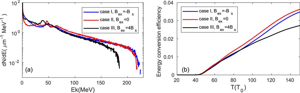
The energy spectra of the accelerated protons for the three cases at t = 100T0 are shown in Fig. 1(a). We can see that there is very little difference in the maximum energies of the protons between cases I and II, suggesting that the magnetization effect indeed plays a rather limited role in the high-energy proton acceleration, especially for the highest-energy protons. This can be explained physically as follows. On the one hand, it should be noted that because of the competition between the electric and magnetic effects on the proton acceleration, the reduction in proton energy depends on the strength ratio between
![]()
Figure 1.(a) Proton energy spectra for cases I (blue), II (red), and III (black) at
The magnetization effect on proton dynamics can be seen more clearly by inspecting the proton angular distributions in Figs. 2(a)–2(c). For all three cases, a hollow ring structure at low proton energies is observed. It is interesting to see from a comparison of the ring diameters that the divergence of the low-energy protons is greatest in case I, for which the magnetization effect is completely inhibited. This is in contrast to the expectation that the self-generated B-field will lead to a greater deflection of the accelerated protons. In fact, the increased divergence of the protons in the nonmagnetization case can be explained as follows. As the ions are accelerated by the sheath field, the rear surface of the target is deformed, becoming curved as depicted in Figs. 2(d)–2(f), owing to the plasma expansion. This curvature of the rear surface results in the generation of a transverse component of the sheath field, Ey = ∂(nekTe)/∂y. In the absence of the magnetization effect, Ey can grow to a high level, as shown in Fig. 2(g), thus strongly deflecting the accelerated ions. Instead, in the presence of the magnetization effect, the hot electrons become highly magnetized, i.e., they perform gyro-motion on the target surface with a Larmor radius rB = γmeve/eB. This gyro-motion of the hot electrons tends to inhibit the generation of the transverse sheath field Ey, as shown in Figs. 2(h) and 2(i). As a result, the protons in the magnetized case are less deflected by the transverse sheath field, and thus exhibit a much smaller divergence. When the magnetization effect is enhanced, i.e., in case III, the proton divergence is found to increase slightly, owing to the enhanced deflection by the increased
![]()
Figure 2.(a)–(c) Proton angular distributions at
The spatial distributions of the self-generated B-fields at t = 75T0 in the three cases are shown in Figs. 2(j)–2(l). It should be noted that the escaping electrons and ions actually experience the modified B-field
It is known that sheath field evolution is dominated by the collective dynamics of hot electrons at the rear side.11 To investigate hot-electron dynamics under different magnetization conditions, the time-integrated spectra of the forward and backward electrons as they pass by the boundaries placed at the rear side of the target (x = 26 µm) are calculated, with the results shown in Fig. 3. It can be observed that the spectra of the forward electrons are nearly identical for the three cases, indicating that the generation of hot electrons at the front side of the target is little affected by modification of the magnetization conditions at the rear side. It can thus be expected that these hot electrons escape into the vacuum to generate the same sheath fields at the rear side of the target for all three cases. Owing to reflection by both the sheath E- and B-fields, these hot electrons return to the target, and the sheath fields thus become weaker. As can be seen in Fig. 3(b), the return (backward) electrons in cases I and II have nearly the same spectra, which may be because the backward hot electrons are dominated by the sheath E-field rather than by the self-generated B-field since the magnetization effect is small in realistic TNSA scenarios. In case III, however, it can be seen that many more electrons with high energies are reflected, owing to the enhanced magnetization effect. The enhancement of the returning electrons in this case finally results in more weakening of the sheath field, thus giving rise to a significant reduction in the maximum energy of accelerated protons, as observed in Fig. 1.
![]()
Figure 3.Time-integrated spectra of (a) the forward and (b) the backward electrons as they pass by the boundaries placed at the target rear side (
To clearly reveal the dynamics of the accelerated protons under different magnetization conditions, we examine the trajectories of two sample protons. The first sample proton is initially located at the position (25.02, 0 µm) corresponding to the highest-energy protons accelerated on the axis, where y = 0 corresponds to the laser axis. As shown in Fig. 4(a), the on-axis protons for all three cases are accelerated along the central axis. There is little deflection, since the Bz and Ey fields vanish on the axis. As can be seen in Fig. 4(b), the longitudinal sheath field Ex experienced by the on-axis proton in case I is almost same as that in case II, indicating that the accelerating field is not affected much by the presence of the surface B-field generated in a realistic TNSA scenario. However, in case III, the on-axis sheath field is reduced both in strength and spatial scale, resulting in a lower proton energy gain. The inhibition of the sheath field in this case can be attributed to the strongly magnetized electrons drifting away from the center of the sheath, as will be discussed in Sec. III.
![]()
Figure 4.(a) and (b) Evolution of an on-axis proton initially located at (25.02, 60
We also track another proton initially located at the off-axis position (25.02, −15 µm) where the self-generated B-field is most intense. Figure 4(c) shows that the off-axis proton is deflected outward in all three cases, i.e., toward regions where the sheath field is lower. In fact, it is found that the off-axis proton in case I is deflected mostly by the transverse electric field Ey, while in the other two cases it is deflected mostly by the azimuthal B-field Bz because in these two cases Ey is strongly inhibited [see Fig. 4(d)]. Since low-energy protons are strongly deflected by Ey in the non-magnetized case, they have a larger divergence than in the magnetized case, as is observed in Fig. 2.
III. ANALYTICAL MODEL OF MAGNETIZATION EFFECT
Many theoretical models have been proposed to describe ion acceleration in the TNSA scenario.24–27 In most of these models, the system is described as a neutral plasma consisting of hot electrons, in which the ions acquire kinetic energies in the course of sheath evolution. This approach is therefore similar to the classic description of plasma expansion into vacuum.20,28,29 An analytical solution for the plasma expansion can be found in the quasineutral approximation using a self-similar theory. Two interpolation formulas for the electric field and ion velocity at the ion front were obtained by Mora using a Lagrangian fluid code.20 In all of these models, however, a 1D geometry, consistent with the electrostatic assumption, is usually adopted, while the influence of the self-generated B-field is neglected. Here, an extended TNSA model including the
In the presence of the self-generated B-field, the electrons at the rear of the target become magnetized and drift away from the center of the sheath under the action of the
Integration of Eq. (4) gives
To analyze the magnetization effect more quantitatively, in principle we need self-consistent solutions for both ϕ and Ar. However, it does not seem possible to obtain such solutions, since the magnetic field generation is a multidimensional problem. To proceed further, therefore, we assume that the self-similar behavior of the magnetic potential is approximately the same as that of the electric potential. This is a reasonable assumption, because both the magnetic and electric fields stem from the same source, namely, the ejection of hot electrons. Therefore, we assume Ar(ξ) = −αϕ(ξ), where α > 0 is a constant. Here, α also represents the ratio between the strength of the azimuthal magnetic field and that of the electric field, i.e., α ≡ c|Bθ|/|Ez|. Under this assumption, Eq. (6) becomes the Boltzmann relation
Next, we consider the ion fluid motion in the electric potential. The equations of continuity and motion for the initially cold ions are
In the presence of a B-field, the rate of reduction in ion energy caused by the B-field can be estimated as
IV. INHIBITED ION ACCELERATION AT HIGH LASER INTENSITIES
The above considerations suggest that the magnetization effect plays a rather limited role in hampering ion acceleration, and hence it cannot explain the degraded scaling of the maximum proton energy with increasing laser intensity that is observed in both the PIC simulations and experimental results.33,34 To gain a more complete understanding of the inhibited ion acceleration at high laser intensities, we also carry out 2D PIC simulations in which the laser intensity is varied over three orders of magnitude while the target parameters and the other laser parameters are kept fixed at the same values as in the preceding simulations. The maximum proton energy
![]()
Figure 5.Maximum proton energy
In contrast to the sheath field
V. CONCLUSION
PIC simulations have been used to study the effects of a spontaneous surface B-field on proton acceleration at high laser intensities. Magnetization effects of the self-generated B-field are observed, but are not strong enough to affect sheath-driven proton acceleration, especially in realistic TNSA scenarios. A considerable reduction in proton energy is observed when an intense external B-field is present and the Lorentz force on a charged particle becomes much more intense than in the case of TNSA, but this may not occur in realistic scenarios. Also, it is found that since the gyro-motion of electrons in the self-generated B-field tends to suppress the growth of a transverse sheath field, deflection of low-energy protons by the latter field is prevented. As a result, the divergence of low-energy protons is actually increased by the self-generated B-field.
A theoretical model including the
Finally, it has been argued that the degraded scaling of proton energy at high laser intensities can be attributed to the magnetization effect of the self-generated B-field. In fact, our PIC results presented here indicate better scaling of the sheath field at higher laser intensities, and thus cannot support the view that the sheath field is inhibited by strong magnetization effects. Instead, it has been shown that the degraded scaling of proton energy can be reasonably explained by the decreased acceleration time due to the increased sheath field at high laser intensities. This more complete understanding of the magnetization effect on ion acceleration will have important implications for the design of ion sources at upcoming multi-PW laser facilities.36–38
ACKNOWLEDGMENTS
Acknowledgment. This work was supported by the National Key Program for S&T Research and Development (Grant No. 2018YFA0404804), the Science Challenge Project (Grant No. TZ2016005 and TZ2018005), the Science and Technology on Plasma Physics Laboratory (Grant No. 6142A04200101), and the National Natural Science Foundation of China (Grant No. 11805181).
References
[1] M.Nishikino, K.Sato, A.Yogo et al. Application of laser-accelerated protons to the demonstration of DNA double-strand breaks in human cancer cells. Appl. Phys. Lett., 94, 181502(2009).
[2] M.Baumann, E.Beyreuther, K.Zeil et al. Dose-controlled irradiation of cancer cells with laser-accelerated proton pulses. Appl. Phys. B, 110, 437-444(2013).
[3] J. D.Bonlie, H.Chen, S. C.Wilks et al. Making relativistic positrons using ultraintense short pulse laser. Phys. Plasmas, 16, 122702(2009).
[4] I.Alber, V.Bagnoud, M.Roth et al. Proton acceleration experiments and warm dense matter research using high power lasers. Plasma Phys. Controlled Fusion, 51, 124039(2009).
[5] T. E.Cowan, M. H.Key, M.Roth et al. Fast ignition by intense laser-acceleated proton beams. Phys. Rev. Lett., 86, 436-439(2001).
[6] B. J.ALbright, J. C.Fernández, J. J.Honrubia et al. Progress and prospects of ion-driven fast ignition. Nucl. Fusion, 49, 065004(2009).
[7] B. J.ALbright, F. N.Beg, J. C.Fernández et al. Fast ignition with laser-driven proton and ion beams. Nucl. Fusion, 54, 054006(2014).
[8] M.Borghesi, A.Macchi, M.Passoni. Ion acceleration by superintense laser-plasma interaction. Rev. Mod. Phys., 85, 751-793(2013).
[9] M.Borghesi, B.Qiao, M.Zepf et al. Stable GeV ion-beam acceleration from thin foils by circularly polorized laser pulse. Phys. Rev. Lett., 102, 145002(2009).
[10] A.Pukhov, G.Shvets, T.-P.Yu et al. Stable laser-driven proton beam acceleration from a two-ion species ultra thin foil. Phys. Rev. Lett., 105, 065002(2010).
[11] T. E.Cowan, A. B.Langdon, S. C.Wilks et al. Energetic proton generation in ultra-intense laser-solid interactions. Phys. Plasma, 8, 542(2001).
[12] B. J.Albright, J.Cobble, B. M.Hegelich et al. Laser acceleration of quasi-monoenergetic MeV ion beams. Nature, 439, 441-444(2006).
[13] C.Brabetz, O.Deppert, F.Wagner et al. Maximum proton energy above 85 MeV from the relativistic interaction of laser pulses with micrometer thick CH2 targets. Phys. Rev. Lett., 116, 205002(2016).
[14] R. J.Gray, A.Higginson, M.King et al. Near-100 MeV protons via a laser-driven transparency-enhanced hybrid acceleration scheme. Nat. Commun., 9, 724(2018).
[15] A.Korzhimanov, M.Nakatsutsumi, Y.Sentoku et al. Self-generated surface magnetic fields inhibit laserdriven sheath acceleration of high-energy protons. Nat. Commun., 9, 280(2018).
[16] S.Buffechoux, A.Kon, M.Nakatsutsumi et al. Fast focusing of short-pulse lasers by innovative plasma optics toward extreme intensity. Opt. Lett., 35, 2314-2316(2010).
[17] C.McGuffey, N.Nakanii, W.Schumaker et al. Ultrafast electron radiography of magnetic fields in high-intensity laser-solid interactions. Phys. Rev. Lett., 110, 015003(2013).
[18] B.Albertazzi, P.Antici, S. N.Chen et al. Dynamics and structure of self-generated magnetics fields on solids following high contrast, high intensity laser irradiation. Phys. Plasma, 22, 123108(2015).
[19] X. T.He, Z. M.Sheng, Z. M.Zhang et al. Hundreds MeV monoenergetic proton bunch from interaction of 1020−21 W/cm2 circularly polarized laser pulse with tailored complex target. Appl. Phys. Lett., 100, 134103(2012).
[20] P.Mora. Plasma expansion into a vacuum. Phys. Rev. Lett., 90, 185002(2003).
[21] P.Antici, E.d’Humières, J.Fuchs et al. Laser-driven proton scaling laws and new paths towards energy increase. Nat. Phys., 2, 48-54(2006).
[22] M. G.Haines. Saturation mechanisms for the generated magnetic field in nonuniform laser-matter irradiation. Phys. Rev. Lett., 78, 254-257(1997).
[23] S. V.Bulanov, F.Califano, F.Pegoraro. Spatial structure and time evolution of the Weibel instability in collisionless inhomogeneous plasmas. Phys. Rev. E, 56, 963-969(1997).
[24] P.Antici, L.Gremillet, T.Grismayer et al. Modeling target bulk heating resulting from ultra-intense short pulse laser irradiation of solid density targets. Phys. Plasma, 20, 123116-1-123116-8(2013).
[25] M.Lontano, M.Passoni. One-dimensional model of the electrostatic ion acceleration in the ultraintense laser–solid interaction. Laser Particle Beams, 22, 163-169(2004).
[26] M.Lontano, M.Passoni. Theory of light-ion acceleration driven by a strong charge separation. Phys. Rev. Lett., 101, 115001(2008).
[27] L.Bertagna, M.Passoni, A.Zani. Energetic ions from next generation ultraintense ultrashort lasers: Scaling laws for target normal sheath acceleration. Nucl. Instrum. Methods Phys. Res., Sect. A, 620, 46-50(2010).
[28] P.Mora, R.Pellat. Self-similar expansion of a plasma into a vacuum. Phys. Flusids, 22, 2300(1979).
[29] J. E.Allen, P. L.Auer, J. E.Crow. Expansion of a plasma into a vacuum. J. Plasma Phys., 14, 65-76(1975).
[31] E.d’Humières, A.Debayle, J. J.Honrubia et al. Divergence of laser-driven relativistic electron beams. Phys. Rev. E, 82, 036405(2010).
[32] M.Mcmahon, V.Ovchinnikov, D. W.Schumacher et al. Effects of preplasma scale length and laser intensity on the divergence of laser generated hot electrons. Phys. Rev. Lett., 110, 065007(2013).
[33] A.Bigongiari, M.Borghesi, S.Kar et al. Laser-driven proton acceleration: Source optimization and radiographic applications. Plasma Phys. Controlled Fusion, 50, 124040(2008).
[34] M.Borghesi, S. V.Bulanov, J.Fuchs et al. Fast ion generation by high-intensity laser irradiation of solid targets and applications. Fusion Sci. Technol., 49, 412-439(2006).
[35] W. L.Kruer, M.Tabak, S. C.Wilks et al. Absorption of ultra-intense laser pulses. Phys. Rev. Lett., 69, 1383-1386(1992).
[36] Z.Guo, J. Y.Wang, L. H.Yu et al. Improvement of the focusing ability by double deformable mirrors for 10-PW-level Ti: Sapphire chirped pulse amplification laser system. Opt. Express, 26, 026776(2018).
[37] C.Jeon, J.Shin, J. W.Yoon et al. Achieving the laser intensity of 5.5 × 10²² W/cm2 with a wavefront-corrected multi-PW laser. Opt. Express, 27, 020412(2019).
[38] X. M.Zeng, K. N.Zhou, Y. L.Zuo et al. Multi-petawatt laser facility fully based on optical parametric chriped pulse amplification. Opt. Lett., 42, 2014(2017).


Set citation alerts for the article
Please enter your email address

© Copyright 2018-2021 | Chinese Laser Press. All Rights Reserved 沪ICP备15018463号-20