• Photonics Research
  • Vol. 12, Issue 1, 70 (2024)
Mengdi Luo1、†, Jisen Wen1、†, Pengcheng Ma1, Qiuyuan Sun1, Xianmeng Xia1, Gangyao Zhan1, Zhenyao Yang1, Liang Xu1, Dazhao Zhu1、4、*, Cuifang Kuang1、2、3、5、*, and Xu Liu2
Author Affiliations
  • 1Research Center for Intelligent Chips and Devices, Zhejiang Lab, Hangzhou 311100, China
  • 2State Key Laboratory of Extreme Photonics and Instrumentation, College of Optical Science and Engineering, Zhejiang University, Hangzhou 310027, China
  • 3ZJU-Hangzhou Global Scientific and Technological Innovation Center, Hangzhou 311200, China
  • 4e-mail: zhudz@zhejianglab.com
  • 5e-mail: cfkuang@zju.edu.cn
  • show less
    DOI: 10.1364/PRJ.499405 Cite this Article Set citation alerts
    Mengdi Luo, Jisen Wen, Pengcheng Ma, Qiuyuan Sun, Xianmeng Xia, Gangyao Zhan, Zhenyao Yang, Liang Xu, Dazhao Zhu, Cuifang Kuang, Xu Liu. Three-dimensional nanoscale vortex line visualization and chiral nanostructure fabrication of tightly focused multi-vortex beams via direct laser writing[J]. Photonics Research, 2024, 12(1): 70 Copy Citation Text show less
    (a) Scheme of the experimental setup. The MVB is formed by applying phase-only modulation to a Gaussian beam. The initial phase distribution loaded on SLM is demonstrated here with a=0.25w0, (a1) m=2 and (a2) m=3 as examples. Then, the generated MVB is coupled into a high NA immersion-type objective (MO) and focused onto the sample, consisting of a particle sitting on a glass substrate. The sample is embedded in immersion oil index matched to the substrate. The backward-scattered and reflected light is imaged with a camera. This is also the experimental setup for 2PP-DLW by MVBs. AOM, acousto-optic modulator; M, mirror; HWP, half-wave plate; PBS, polarized beam splitter; L, lens; PR, prism reflector; SLM, spatial light modulator; DM, dichroic mirror; BS, beam splitter. (b) Tight focusing system. (c) Simulated intensity distributions along the propagation direction in the focus region of an objective with NA of 1.45.
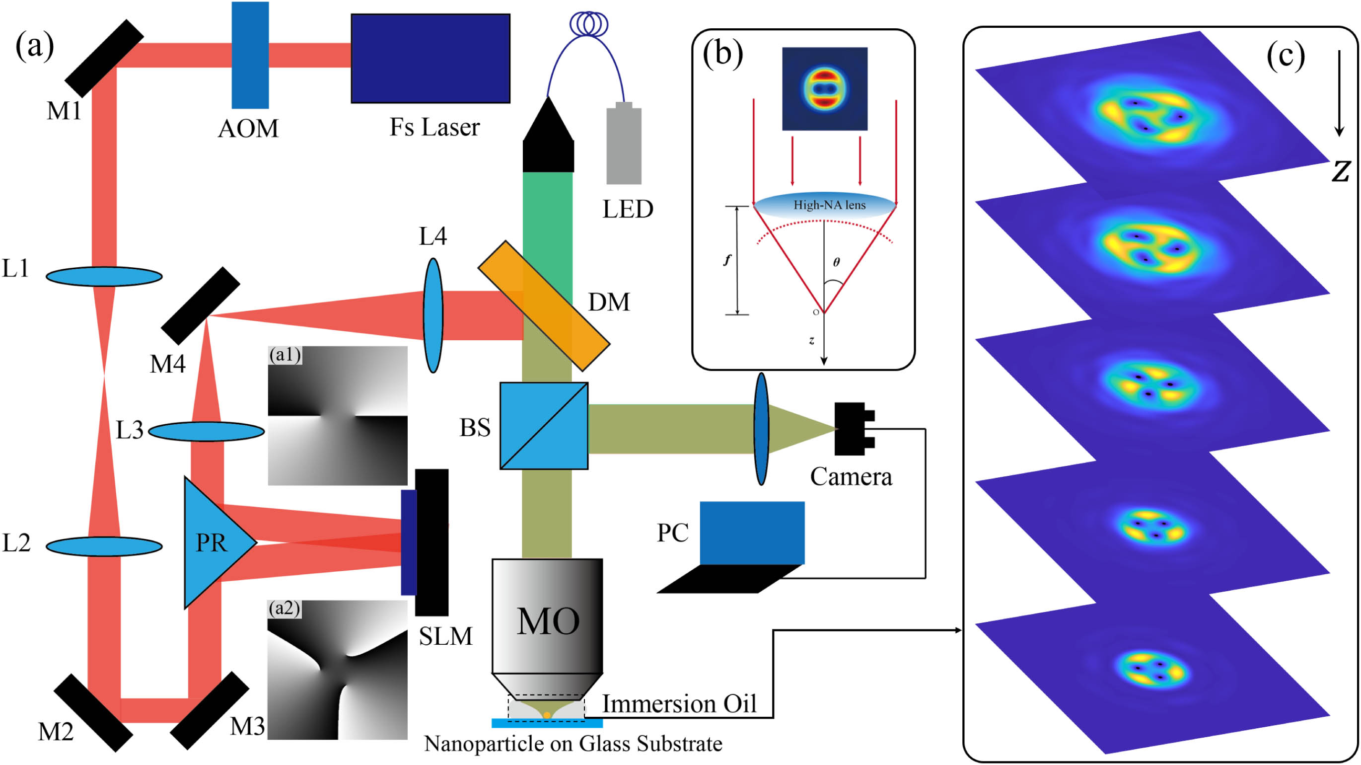
    Fig. 1. (a) Scheme of the experimental setup. The MVB is formed by applying phase-only modulation to a Gaussian beam. The initial phase distribution loaded on SLM is demonstrated here with a=0.25w0, (a1) m=2 and (a2) m=3 as examples. Then, the generated MVB is coupled into a high NA immersion-type objective (MO) and focused onto the sample, consisting of a particle sitting on a glass substrate. The sample is embedded in immersion oil index matched to the substrate. The backward-scattered and reflected light is imaged with a camera. This is also the experimental setup for 2PP-DLW by MVBs. AOM, acousto-optic modulator; M, mirror; HWP, half-wave plate; PBS, polarized beam splitter; L, lens; PR, prism reflector; SLM, spatial light modulator; DM, dichroic mirror; BS, beam splitter. (b) Tight focusing system. (c) Simulated intensity distributions along the propagation direction in the focus region of an objective with NA of 1.45.
    (a1)–(a4) Theoretical and (b1)–(b4) experimental intensity distributions of the MVBs at the focal plane (z=0) with an oil immersion objective (NA=1.45, n=1.518) and (a1), (b1) m=2, a=0.5 mm; (a2), (b2) m=2, a=0.75 mm; (a3), (b3) m=3, a=0.5 mm; (a4), (b4) m=3, a=0.75 mm. Scale bar: 100 nm.
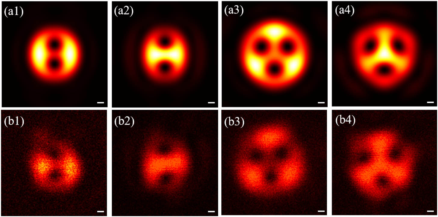
    Fig. 2. (a1)–(a4) Theoretical and (b1)–(b4) experimental intensity distributions of the MVBs at the focal plane (z=0) with an oil immersion objective (NA=1.45, n=1.518) and (a1), (b1) m=2, a=0.5  mm; (a2), (b2) m=2, a=0.75  mm; (a3), (b3) m=3, a=0.5  mm; (a4), (b4) m=3, a=0.75  mm. Scale bar: 100 nm.
    (a) Visualization of numerically determined 3D evolution of phase vortices. The intensity distribution at the focal plane is also shown. The red dots here represent the vortices. (b) Top view of (a). (c) Numerical results for the evolution of MVBs at different propagation distance z with m=2 and a=0.375 mm in the tight focusing system as shown in Fig. 1(b). Vortices are marked white dots with the indication of corresponding indices. (d) SEM photo of nanostructure of positive photoresist fabricated by single exposure 2PP-DLW recording the evolution of the phase vortices.
    Fig. 3. (a) Visualization of numerically determined 3D evolution of phase vortices. The intensity distribution at the focal plane is also shown. The red dots here represent the vortices. (b) Top view of (a). (c) Numerical results for the evolution of MVBs at different propagation distance z with m=2 and a=0.375  mm in the tight focusing system as shown in Fig. 1(b). Vortices are marked white dots with the indication of corresponding indices. (d) SEM photo of nanostructure of positive photoresist fabricated by single exposure 2PP-DLW recording the evolution of the phase vortices.
    (a) Numerically calculated results of the evolution of phase vortices with m=3 and a=0.375 mm. The vortices are marked red dots. (b) The 2PP-DLW single-exposure results are observed by SEM.
    Fig. 4. (a) Numerically calculated results of the evolution of phase vortices with m=3 and a=0.375  mm. The vortices are marked red dots. (b) The 2PP-DLW single-exposure results are observed by SEM.
    Propagation evolution and 3D intensity distributions of MVBs with a=0.5 mm and (a1) m=2, (b1) m=3, (c1) m=5. SEM photos of the fabricated 3D chiral nanostructures and the corresponding arrays via tightly focused MVBs with a=0.75 mm and (a2), (a3) m=2; (b2), (b3) m=3; (c2), (c3) m=5.
    Fig. 5. Propagation evolution and 3D intensity distributions of MVBs with a=0.5  mm and (a1) m=2, (b1) m=3, (c1) m=5. SEM photos of the fabricated 3D chiral nanostructures and the corresponding arrays via tightly focused MVBs with a=0.75  mm and (a2), (a3) m=2; (b2), (b3) m=3; (c2), (c3) m=5.
    (a) SEM photos of the fabricated 3D chiral nanostructures with different laser power and single exposure time. (b) Dependence of the diameters of the fabricated nanostructures on the laser power and exposure time.
    Fig. 6. (a) SEM photos of the fabricated 3D chiral nanostructures with different laser power and single exposure time. (b) Dependence of the diameters of the fabricated nanostructures on the laser power and exposure time.
    Principle of measuring vortex dichroism spectra. (a) Experimental setup for measuring VD. The phase-only SLM is used to imprint the vortex phase onto a Gaussian incident continuous beam. Then the vortex beam is tightly focused on the chiral nanostructure through the objective, and the reflected light is collected by CCD. The simulation and experimental results of intensity distributions passing through the nanostructures with (b1), (b2) l=10 and (c1), (c2) l=−10 are demonstrated, respectively.
    Fig. 7. Principle of measuring vortex dichroism spectra. (a) Experimental setup for measuring VD. The phase-only SLM is used to imprint the vortex phase onto a Gaussian incident continuous beam. Then the vortex beam is tightly focused on the chiral nanostructure through the objective, and the reflected light is collected by CCD. The simulation and experimental results of intensity distributions passing through the nanostructures with (b1), (b2) l=10 and (c1), (c2) l=10 are demonstrated, respectively.
    (a) Optical vortical dichroism measurements of the chiral nanostructure versus topological charge |l|. The insert is the SEM photo of the measured nanostructure with D=2.92 μm. (b) SEM photo of the nanostructure with different chiral properties in the inner area and outer area.
    Fig. 8. (a) Optical vortical dichroism measurements of the chiral nanostructure versus topological charge |l|. The insert is the SEM photo of the measured nanostructure with D=2.92  μm. (b) SEM photo of the nanostructure with different chiral properties in the inner area and outer area.
    OAM spectrum analysis of the reflected OAM beams with different incident topological charges: (a) l=−5; (b) l=5; (c) l=−10; (d) l=10. The insert figures are the respective phase distributions.
    Fig. 9. OAM spectrum analysis of the reflected OAM beams with different incident topological charges: (a) l=5; (b) l=5; (c) l=10; (d) l=10. The insert figures are the respective phase distributions.
    Mengdi Luo, Jisen Wen, Pengcheng Ma, Qiuyuan Sun, Xianmeng Xia, Gangyao Zhan, Zhenyao Yang, Liang Xu, Dazhao Zhu, Cuifang Kuang, Xu Liu. Three-dimensional nanoscale vortex line visualization and chiral nanostructure fabrication of tightly focused multi-vortex beams via direct laser writing[J]. Photonics Research, 2024, 12(1): 70
    Download Citation