• Journal of Inorganic Materials
  • Vol. 38, Issue 9, 1103 (2023)
Wanli FANG1、2, Lili SHEN2, Haiyan LI2, Xinyu CHEN2, Zongqi CHEN2, Chunhui SHOU3, Bin ZHAO1、*, and Songwang YANG1、2、4、*
Author Affiliations
  • 11. School of Materials and Chemistry, University of Shanghai for Science and Technology, Shanghai 200093, China
  • 22. CAS Key Laboratory of Materials for Energy Conversion, Shanghai Institute of Ceramics, Chinese Academy of Sciences, Shanghai 201899, China
  • 33. Key Laboratory of Solar Energy Utilization & Energy Saving Technology of Zhejiang Province, Zhejiang Energy Group R&D, Hangzhou 310003, China
  • 44. Center of Materials Science and Optoelectronics Engineering, University of Chinese Academy of Sciences, Beijing 100049, China
  • show less
    DOI: 10.15541/jim20230002 Cite this Article
    Wanli FANG, Lili SHEN, Haiyan LI, Xinyu CHEN, Zongqi CHEN, Chunhui SHOU, Bin ZHAO, Songwang YANG. Effect of Film Formation Processes of NiOx Mesoporous Layer on Performance of Perovskite Solar Cells with Carbon Electrodes [J]. Journal of Inorganic Materials, 2023, 38(9): 1103 Copy Citation Text show less
    (a) Schematic illustration and (b) work function of the device, cross-sectional SEM images of C-PSCs: (c) device A, (d) device B and (e) device C, and (f) element distribution in the direction of the white arrow in (e)
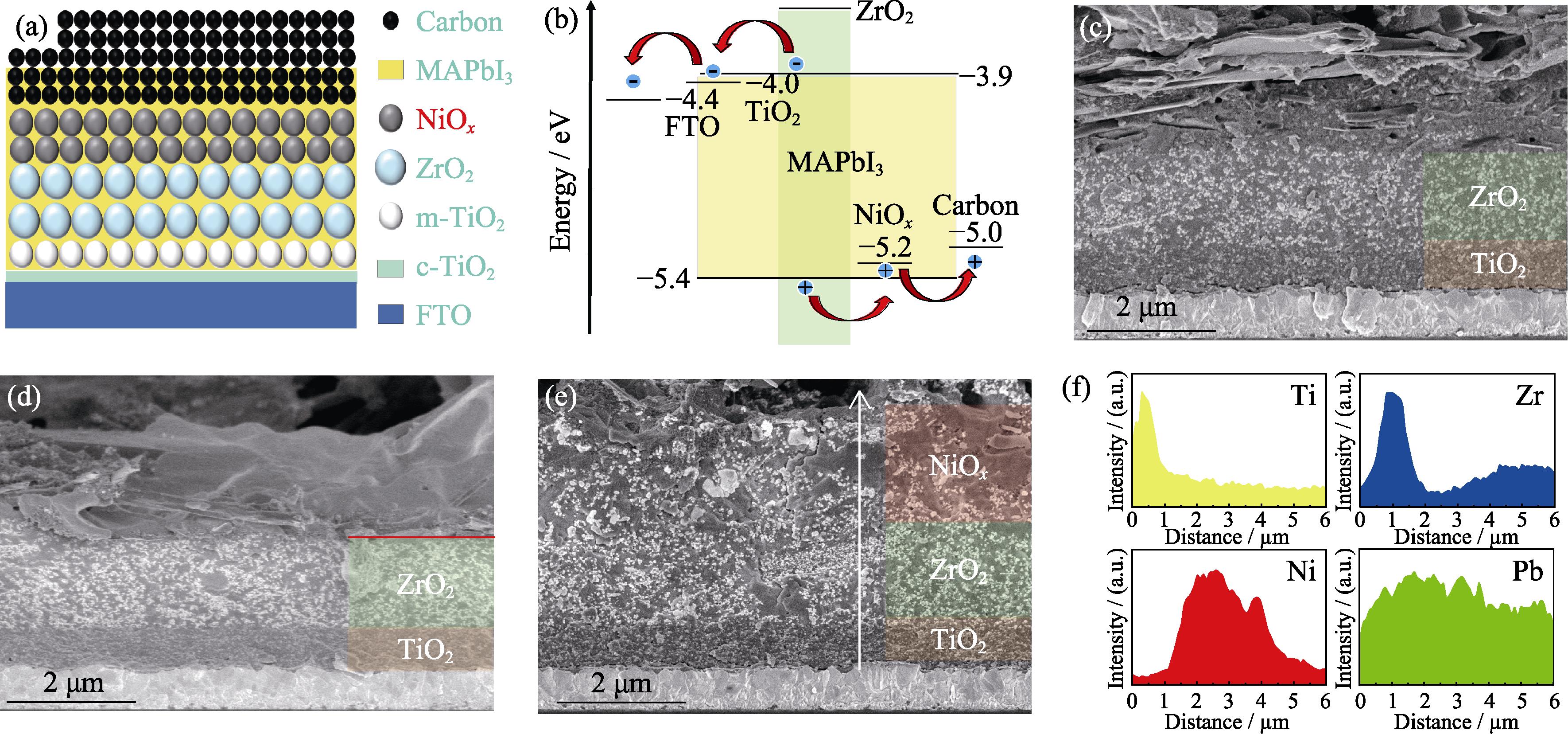
    1. (a) Schematic illustration and (b) work function of the device, cross-sectional SEM images of C-PSCs: (c) device A, (d) device B and (e) device C, and (f) element distribution in the direction of the white arrow in (e)
    Photographs of NiOx dispersions for (left) spin-coating (SC), for (right) screen-printing (SP) (a) before and (b) after standing for 30 min
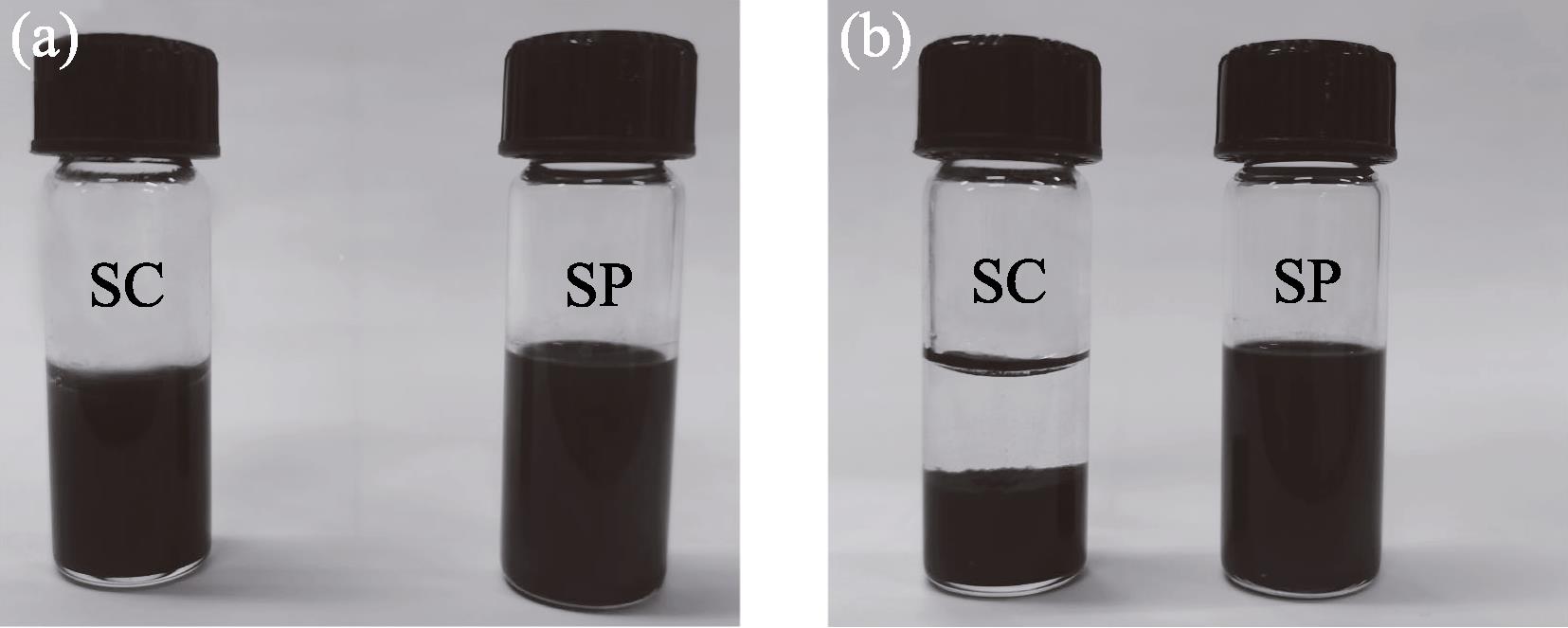
    2. Photographs of NiOx dispersions for (left) spin-coating (SC), for (right) screen-printing (SP) (a) before and (b) after standing for 30 min
    SEM images of (a) ZrO2 mesoporous film, (b) spin- coated and (c) screen-printed NiOx films, and (d) PL spectra for sample A (ZrO2/MAPbI3), sample B (ZrO2/NiOx (spin-coated)/ MAPbI3), and sample C (ZrO2/NiOx(screen-printed)/MAPbI3)
    3. SEM images of (a) ZrO2 mesoporous film, (b) spin- coated and (c) screen-printed NiOx films, and (d) PL spectra for sample A (ZrO2/MAPbI3), sample B (ZrO2/NiOx (spin-coated)/ MAPbI3), and sample C (ZrO2/NiOx(screen-printed)/MAPbI3)
    (a) XRD patterns of MAPbI3 in different devices and (b) local magnified XRD patterns in range of 13.6°-14.6°
    4. (a) XRD patterns of MAPbI3 in different devices and (b) local magnified XRD patterns in range of 13.6°-14.6°
    (a-c) J-V curves and (d) incident photon-to-electron conversion efficiency (IPCE) spectra and the integrated current density curves of different devices(a) Forward and reverse scans of device A, B and C; (b) Different thicknesses of NiOx layer; (c) The optimum cells of device A and device C; Colorful figures are available on website
    5. (a-c) J-V curves and (d) incident photon-to-electron conversion efficiency (IPCE) spectra and the integrated current density curves of different devices(a) Forward and reverse scans of device A, B and C; (b) Different thicknesses of NiOx layer; (c) The optimum cells of device A and device C; Colorful figures are available on website
    (a) J-V curves under dark conditions, (b) light-intensity dependence of VOC (solid line: linear fitting), (c) transient photovoltage (TPV) decay curves, (d) transient photocurrent (TPC) decay curves, (e) Nyquist plots measured in the dark, and (f) Mott-Schottky plots for device A and device C; Colorful figures are available on website
    6. (a) J-V curves under dark conditions, (b) light-intensity dependence of VOC (solid line: linear fitting), (c) transient photovoltage (TPV) decay curves, (d) transient photocurrent (TPC) decay curves, (e) Nyquist plots measured in the dark, and (f) Mott-Schottky plots for device A and device C; Colorful figures are available on website
    Long-term storage stability of PSCs in air with relative humidity of 30%-40%(a) JSC; (b) VOC; (c) FF; (d) PCE
    7. Long-term storage stability of PSCs in air with relative humidity of 30%-40%(a) JSC; (b) VOC; (c) FF; (d) PCE
    XRD pattern of NiOx nanoparticles prepared by chemical precipitation method
    S1. XRD pattern of NiOx nanoparticles prepared by chemical precipitation method
    Low magnification cross-sectional SEM images of (a) device B and (b) device C
    S2. Low magnification cross-sectional SEM images of (a) device B and (b) device C
    High magnification top-view SEM images of screen- printed (a) ZrO2 and (b) NiOx films
    S3. High magnification top-view SEM images of screen- printed (a) ZrO2 and (b) NiOx films
    Certified efficiency measurement report of device C
    S4. Certified efficiency measurement report of device C
    SampleVOC/V JSC/(mA·cm-2) FF/%PCE/%
    ReverseForwardReverseForwardReverseForwardReverseForward
    Device A0.7790.76423.4523.3863.6055.4711.629.91
    Device B0.8220.82023.6223.5660.6660.2611.7811.64
    Device C0.9040.90323.5723.5663.2962.9813.4913.40
    Table 1.

    Photovoltaic parameters for different devices with an aperture area of 0.07 cm2 under 1 sun (100 mW·cm-2) illumination

    SampleVOC/V JSC/(mA·cm-2) FF/%PCE/%
    NiOx (0.8 μm)0.89822.3661.6612.38
    NiOx (1.6 μm)0.93222.6862.8713.28
    NiOx (2.4 μm)0.93920.8654.4310.66
    Table 2.

    Photovoltaic parameters of devices with different thicknesses of screen-printed NiOx layer

    DeviceVOC/V JSC/(mA·cm-2) FF/%PCE/%
    Device A0.84023.3961.0011.95
    Device C0.91025.0464.1314.63
    Table 3.

    Photovoltaic parameters of device A and C

    Wanli FANG, Lili SHEN, Haiyan LI, Xinyu CHEN, Zongqi CHEN, Chunhui SHOU, Bin ZHAO, Songwang YANG. Effect of Film Formation Processes of NiOx Mesoporous Layer on Performance of Perovskite Solar Cells with Carbon Electrodes [J]. Journal of Inorganic Materials, 2023, 38(9): 1103
    Download Citation