
Guo-Wei Zhang, Yu-Yang Ding, Wei Chen, Fang-Xiang Wang, Peng Ye, Guan-Zhong Huang, Shuang Wang, Zhen-Qiang Yin, Jun-Ming An, Guang-Can Guo, Zheng-Fu Han, "Polarization-insensitive interferometer based on a hybrid integrated planar light-wave circuit," Photonics Res. 9, 2176 (2021)
- Photonics Research
- Vol. 9, Issue 11, 2176 (2021)
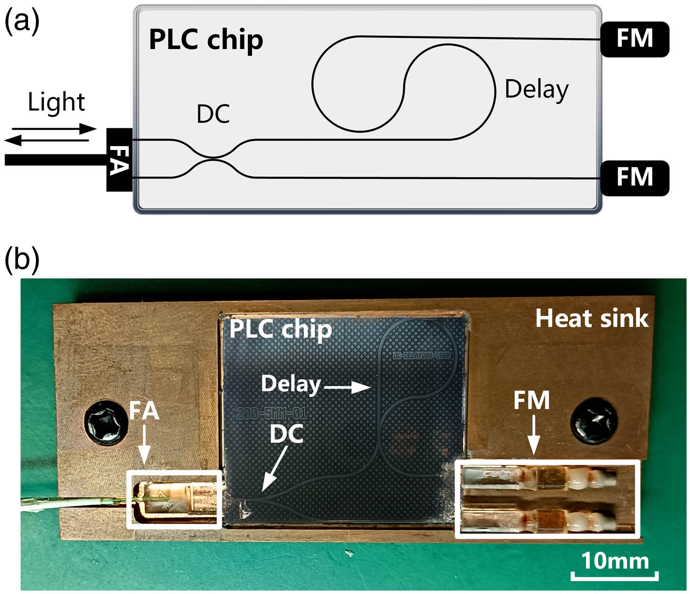
Fig. 1. AFMI device. (a) Scheme of our AFMI. The interferometer combines an FA for photon coupling, a DC with the splitting ratio of 50:50, a 200 ps delay line, and two FMs; (b) photograph of our AFMI. The size of the chip is about 27.8 mm × 23.1 mm
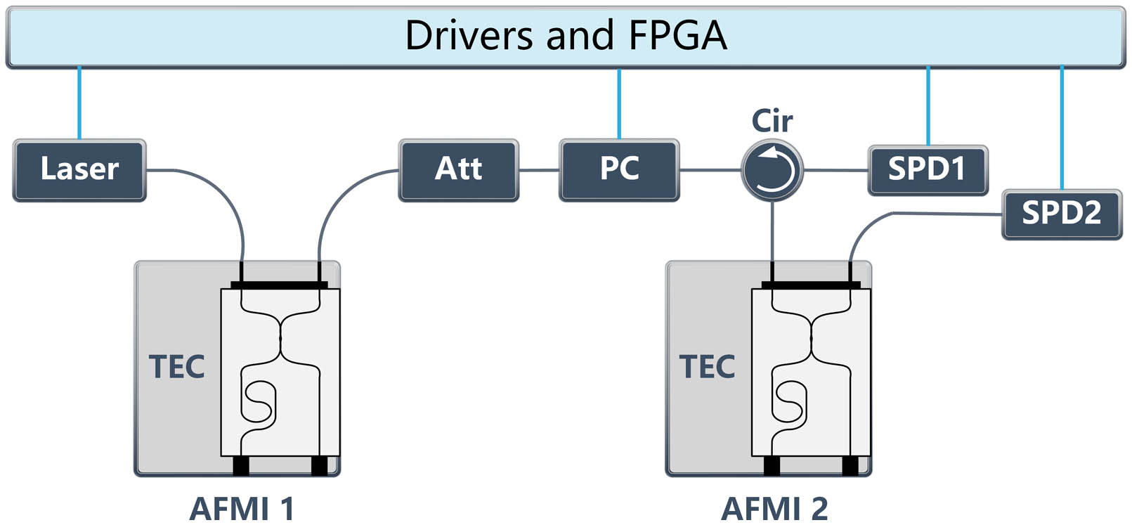
Fig. 2. Experimental setup to evaluate the characteristics of our AFMIs. Laser, gain-switch laser source; TEC, temperature controller; ATT, light attenuator; PC, polarization controller; Cir, circulator; SPD1 and SPD2, single-photon detectors.
Fig. 3. Interference results with temperature scanning of AFMI1. The black dots are measured data points, and the red line is the corresponding curve fitting.
Fig. 4. Interference results for fixed polarization states.
Fig. 5. Results of continuous polarization scramble test. (a) Diagram of interference visibility with and without continuous polarization scramble; insets, the diagram of normalized Stokes parameters and interference visibility during test; (b) visibilities in the range of 10°C–35°C with and without polarization scramble. The 3 σ
Fig. 6. Results of long-term phase stability test. Shadow areas represent the 1 σ
Fig. 7. Results of delay difference calculation. (a) Variations of the visibilities for temporal and amplitude mismatch. The red triangle is where our AFMIs stand. (b) Normalized light intensity after propagating through two AFMIs, detected by an SPD. The Δ T


Set citation alerts for the article
Please enter your email address

© Copyright 2018-2021 | Chinese Laser Press. All Rights Reserved 沪ICP备15018463号-20