
Guo-Wei Zhang, Yu-Yang Ding, Wei Chen, Fang-Xiang Wang, Peng Ye, Guan-Zhong Huang, Shuang Wang, Zhen-Qiang Yin, Jun-Ming An, Guang-Can Guo, Zheng-Fu Han, "Polarization-insensitive interferometer based on a hybrid integrated planar light-wave circuit," Photonics Res. 9, 2176 (2021)
- Photonics Research
- Vol. 9, Issue 11, 2176 (2021)
Abstract
1. INTRODUCTION
Photons are the most critical information carriers and perform high-fidelity operations in up-to-date information-processing systems. The interferometer plays an essential role in various information-processing applications, either in classical or quantum research fields, including metrology and sensing [1], coherent optical communication [2], quantum entanglement measurement [3], quantum communication [4–7], and many other fields [8–12].
Interference visibility and stability are the most concerning issues when designing an interferometer. The former relates to measurement precision, and the latter decides whether the system can operate for a long time effectively. Notably, the recent advancements of the applications like quantum information processing require high-performance interferometers. For example, quantum key distribution (QKD) is one of the most promising quantum information technologies that has been deployed in the laboratory and field. For most of the phase-encoded QKD systems, the intrinsic part of the quantum bit error rate (QBER) induced by the optical components is correlated with the interference visibility
The temperature fluctuation, vibration, and stress variety in the environment will affect the birefringence of the optical components and fibers, which will disturb the polarization of the interfering photons. By monitoring the interference visibility, we can evaluate this disturbance. Since the birefringence in fiber channels is inevitable and uncontrollable, it is a more critical challenge to practical fiber QKD [15]. Many countermeasures have been proposed to overcome polarization disturbance [13,16–20], which can be classified into active and passive categories. Active polarization compensating components have been adopted in practical QKD systems [16–18], which is effective but may increase the complexity, insertion loss, and time-consumption of the system. Birefringence variations can be automatically compensated for in QKD systems using passive schemes, such as the “plug-and-play” system [19], Faraday–Michelson system [13], and Faraday–Sagnac–Michelson system [20]. Although the two-way system like plug-and-play system may suffer from Trojan horse attacks [21], these schemes have been deployed in complex field environments and demonstrated their low QBER and outstanding long-term stability.
Sign up for Photonics Research TOC. Get the latest issue of Photonics Research delivered right to you!Sign up now
For applications like QKD, a pair of asymmetric interferometers is typically placed in different locations. The difference in ambient temperature of the interferometers induces a phase drift that causes the variations of visibility. Generally, we can compensate for the phase shift using phase shifters [22] or eliminate it by isolating the interferometers from complex environments. Although the influence of the temperature variations can be partially resolved using these measures, it is still an engineering challenge to keep long-term stability and high visibility of the interferometers with large arm-length differences for their high sensitivity.
The rapid development of integrated photonics points out a way to solve most of the problems mentioned above [23–25]. Some integrated QKD experiments have been reported recently [26–31], most of which use asymmetric Mach–Zehnder interferometers (AMZIs) for photon phase measurement. The integrated photonic chips (IPCs) make the system stabler in terms of temperature variations and vibrations. However, since most of the waveguides of the IPC platform are polarization-dependent, chip-based QKD systems still suffer from polarization disturbance due to varying birefringence in the channel.
Nambu
We implement and evaluate a hybrid integrated design for asymmetric Faraday–Michelson interferometers (AFMIs) by combining a silica-on-silicon PLC chip and Faraday rotator mirrors (FMs). We cascade two AFMIs and evaluate their interference visibility at the single-photon level. Experimental results show that these interferometers can achieve an average interference visibility of above 99% over 12 h, and the visibility variations are less than 0.5% with an active random polarization perturbation. We verify that the polarization-independent high visibility can be obtained over a wide temperature range from 10°C to 35°C. We also propose a method to calculate the delay difference between two AFMIs using the single-photon interference results, which is essential for QKD systems.
2. DESIGN OF THE AFMI AND EXPERIMENTAL SETUPS
The scheme of the hybrid integrated AFMI is illustrated in Fig. 1(a). The PLC chip contains a directional coupler (DC) with a splitting ratio of 50:50 and two asymmetric waveguides acting as the two arms of the interferometer. Two FMs [19] are coupled and glued to the edge of two waveguides and reflect the photons back to the entrance coupled with a fiber array (FA).
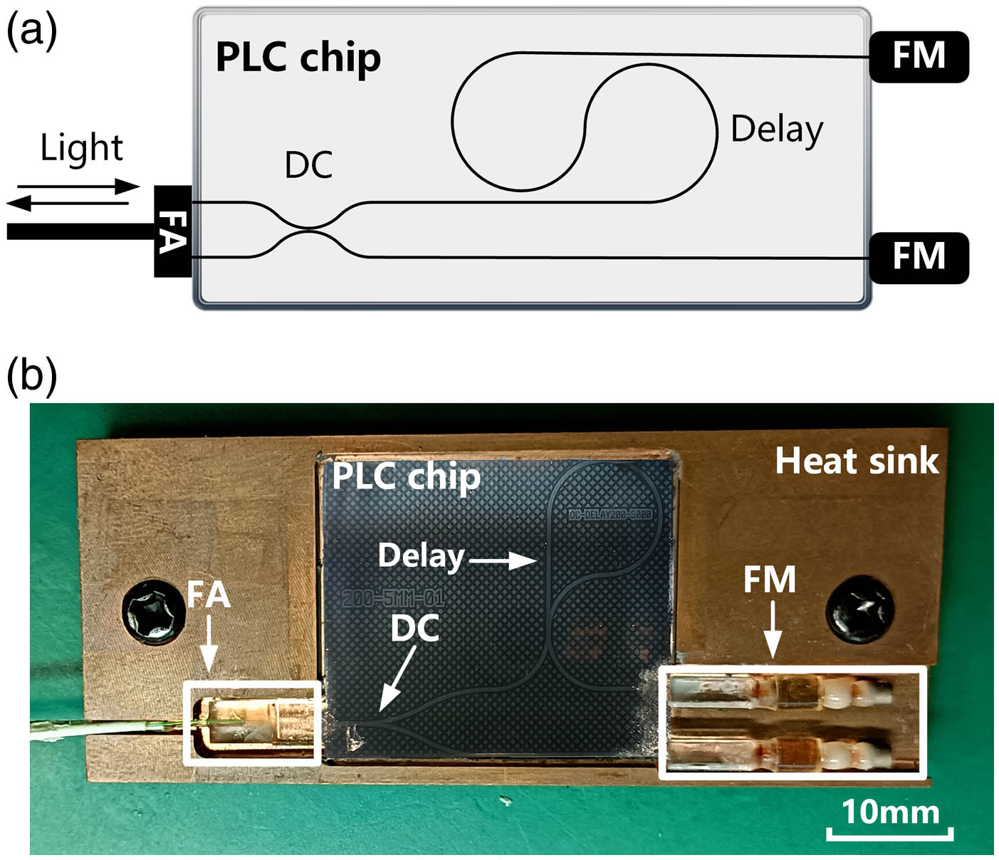
Figure 1.AFMI device. (a) Scheme of our AFMI. The interferometer combines an FA for photon coupling, a DC with the splitting ratio of 50:50, a 200 ps delay line, and two FMs; (b) photograph of our AFMI. The size of the chip is about
The silica PLC platform is used to implement the structure, taking advantage of its relatively low transmission and coupling loss, which are essential for QKD decoders to get a higher SKR. The refractive index difference of the PLC chip for the waveguide core and cladding is 0.75%, and the geometry of the core is
The effect of the FM is to transform an arbitrary input polarization state of the photons into its orthogonal polarization state. If we define the Jones vector of an input state as
Suppose the Jones matrix of a waveguide is
This result indicates that the hybrid integrated AFMI can provide perfect interference with arbitrary input polarization states in principle, which means that the structure can compensate for the polarization perturbance in the chip and the fiber channel.
Figure 2 shows the experimental setup to evaluate the polarization independence and the stability of the hybrid integrated AFMI. We cascade two AFMIs, which act as the optical encoder and decoder module in phase-encoding QKD systems. The insertion loss of the AFMI1 and AFMI2 is 3.99 and 3.31 dB, respectively. The light source is a gain-switch semiconductor laser (Qasky WT-LD200-D) with a pulse width of 50 ps and a central wavelength at 1550 nm. A controllable attenuator and a polarization controller (PC) are placed between the two AFMIs to control the light pulses’ intensity and polarization. The intensity of the light pulses is attenuated to about 0.1 photons per pulse when entering the single-photon detectors (SPDs) to simulate the single-photon interference in QKD systems. The PC is used to simulation the polarization disturbance in the long-haul fiber channel. A circulator (Cir) is placed before the AFMI2 to collect one of the two light beams after interference. Therefore, we can measure both the constructive and destructive ports of the interferometer simultaneously. We adopt two SPDs (Qasky QCRP-SPD-01) with a repetition rate of 1.25 GHz to detect the photon of the interfering peak.
![]()
Figure 2.Experimental setup to evaluate the characteristics of our AFMIs. Laser, gain-switch laser source; TEC, temperature controller; ATT, light attenuator; PC, polarization controller; Cir, circulator; SPD1 and SPD2, single-photon detectors.
The temperature variation of the chips will change the phase of the two arms and affect
3. RESULTS
We first measure the temperature manipulation parameters of the PLC-based AFMIs without any disturbance. We maintain the temperature of one AFMI (AFMI1 in Fig. 2) at 24°C and adjust the TEC to regulate AFMI2’s temperature. The normalized counting rate is shown in Fig. 3, from which we can see that the
![]()
Figure 3.Interference results with temperature scanning of AFMI1. The black dots are measured data points, and the red line is the corresponding curve fitting.
To examine whether this PLC-based AFMI is immune to the polarization disturbance, we next use a PC (Keysight N7788B) to modulate the polarization state of the light input to the AFMI2. The PC can act as a polarization scrambler or set the photons to specific polarization states. We first track the states to one of the six basis states among the Stokes space [34], including linearly polarized,
![]()
Figure 4.Interference results for fixed polarization states.
We also evaluate the interference stability of the AFMIs with random polarization scrambling. We first adjust the interferometers to their maximum interfering point by tuning the temperature of AFMI1 and AFMI2 to 24°C and 24.66°C, respectively. Since the light intensities from the two ports are anticorrelated in principle, the counting rates of SPD1 and SPD2 should reach their maximum and minimum at the same time. We detect single-photon signals from the two ports of the interferometer simultaneously and collect the counting rate every second, which are denoted as
The visibilities with and without random polarization scrambling are shown in Fig. 5(a), which are in the first and the second hour, respectively. In the first hour, the visibilities fluctuate slightly due to the practical control precision of the TEC and the counting fluctuations of the SPDs. When adding the random polarization scrambling, the average interference visibility drops slightly from 99.13% to 98.93%. The fluctuations relatively increase with the range less than 1%, which may also be due to the imperfections of FM devices.
![]()
Figure 5.Results of continuous polarization scramble test. (a) Diagram of interference visibility with and without continuous polarization scramble; insets, the diagram of normalized Stokes parameters and interference visibility during test; (b) visibilities in the range of 10°C–35°C with and without polarization scramble. The
Then we fix the temperature of AFMI1 at 24°C and modify AFMI2’s temperature from 10°C to 35°C to evaluate the impact of temperature variations on the visibilities. The average value and the standard deviation (SD) of the visibility are calculated using the data collected every 10 min. The visibilities with and without polarization scrambling are shown in Fig. 5(b), in which the average fringe visibility is about
Besides the polarization of photons, phase stability is also an essential factor affecting the interference results in practical scenarios. We initialize the temperatures of the two chips at their maximum interference working points, keep the temperature steady, and then perform a free-running measurement over 12 h. The average visibilities are calculated every 10 min, as shown in Fig. 6. It can be seen that visibilities with and without polarization scrambling are
![]()
Figure 6.Results of long-term phase stability test. Shadow areas represent the
The above results indicate that this hybrid integrated AFMI scheme can keep high and stable interference visibilities with arbitrary polarization states over a wide temperature range, which is beneficial for highly demanding applications like QKD. Furthermore, to implement high interfering visibilities between multiple interferometers is a fundamental requirement to support multiuser applications like a QKD network. How to fabricate uniform interferometers is a technical challenge. We derive the method to calculate the arm length or the optical delay difference between the two AFMIs using the interference results. We consider two pulses generated by a gain-switched distributed feedback (DFB) laser and pass through a pair of AFMIs with 50:50 DCs, which is a typical setup in QKD systems up to date. The two pulses can be represented by [35]
From Eq. (7), the visibility is affected by the mismatch of the time (
![]()
Figure 7.Results of delay difference calculation. (a) Variations of the visibilities for temporal and amplitude mismatch. The red triangle is where our AFMIs stand. (b) Normalized light intensity after propagating through two AFMIs, detected by an SPD. The
As shown in Fig. 7(b), the peak-to-peak ratio between the two peaks passing through the two AFMIs is 0.969 and 0.942, respectively. Then the corresponding
4. CONCLUSION
In conclusion, we implement a hybrid integrated AFMI structure by combining a PLC chip with Faraday mirrors. We experimentally demonstrate that the chips have high interference visibilities and can tolerate the polarization disturbance over a wide temperature range. This characteristic makes the chips more robust to the environment and can reduce energy consumption. The delay difference of the interferometers can be precisely measured online using interference results and the model proposed in the text, which will benefit mass production and high-requirement applications in the future.
Acknowledgment
Acknowledgment. We would like to acknowledge Chang Ling Zou for useful discussions. This work was partially carried out at the USTC Center for Micro and Nanoscale Research and Fabrication, and we thank Wen Liu for helpful discussions on manufacturing and packaging.
References
[1] T. Yoshizawa. Handbook of Optical Metrology: Principles and Applications(2017).
[2] T. Okoshi, K. Kikuchi. Coherent Optical Fiber Communications(1988).
[3] I. Ali Khan, J. C. Howell. Experimental demonstration of high two-photon time-energy entanglement. Phys. Rev. A, 73, 031801(2006).
[4] N. Gisin, G. Ribordy, W. Tittel, H. Zbinden. Quantum cryptography. Rev. Mod. Phys., 74, 145-195(2002).
[5] C. H. Bennett, G. Brassard. Quantum cryptography: public key distribution and coin tossing. Theor. Comput. Sci., 560, 7-11(2014).
[6] H.-K. Lo, M. Curty, K. Tamaki. Secure quantum key distribution. Nat. Photonics, 8, 595-604(2014).
[7] F. Xu, X. Ma, Q. Zhang, H.-K. Lo, J.-W. Pan. Secure quantum key distribution with realistic devices. Rev. Mod. Phys., 92, 025002(2020).
[8] D. Bouwmeester, J.-W. Pan, K. Mattle, M. Eibl, H. Weinfurter, A. Zeilinger. Experimental quantum teleportation. Nature, 390, 575-579(1997).
[9] H.-J. Briegel, W. Dür, J. I. Cirac, P. Zoller. Quantum repeaters: the role of imperfect local operations in quantum communication. Phys. Rev. Lett., 81, 5932-5935(1998).
[10] E. Knill, R. Laflamme, G. J. Milburn. A scheme for efficient quantum computation with linear optics. Nature, 409, 46-52(2001).
[11] J. C. Adcock, C. Vigliar, R. Santagati, J. W. Silverstone, M. G. Thompson. Programmable four-photon graph states on a silicon chip. Nat. Commun., 10, 3528(2019).
[12] S. Paesani, Y. Ding, R. Santagati, L. Chakhmakhchyan, C. Vigliar, K. Rottwitt, L. K. Oxenløwe, J. Wang, M. G. Thompson, A. Laing. Generation and sampling of quantum states of light in a silicon chip. Nat. Phys., 15, 925-929(2019).
[13] S. Wang, W. Chen, Z.-Q. Yin, H.-W. Li, D.-Y. He, Y.-H. Li, Z. Zhou, X.-T. Song, F.-Y. Li, D. Wang, H. Chen, Y.-G. Han, J.-Z. Huang, J.-F. Guo, P.-L. Hao, M. Li, C.-M. Zhang, D. Liu, W.-Y. Liang, C.-H. Miao, P. Wu, G.-C. Guo, Z.-F. Han. Field and long-term demonstration of a wide area quantum key distribution network. Opt. Express, 22, 21739-21756(2014).
[14] H.-K. Lo, X. Ma, K. Chen. Decoy state quantum key distribution. Phys. Rev. Lett., 94, 230504(2005).
[15] Y.-Y. Ding, H. Chen, S. Wang, D.-Y. He, Z.-Q. Yin, W. Chen, Z. Zhou, G.-C. Guo, Z.-F. Han. Polarization variations in installed fibers and their influence on quantum key distribution systems. Opt. Express, 25, 27923-27936(2017).
[16] L. Ma, H. Xu, X. Tang. Polarization recovery and auto-compensation in quantum key distribution network. Proc. SPIE, 6305, 630513(2006).
[17] A. R. Dixon, J. F. Dynes, M. Lucamarini, B. Fröhlich, A. W. Sharpe, A. Plews, S. Tam, Z. L. Yuan, Y. Tanizawa, H. Sato, S. Kawamura, M. Fujiwara, M. Sasaki, A. J. Shields. High speed prototype quantum key distribution system and long term field trial. Opt. Express, 23, 7583-7592(2015).
[18] Y.-Y. Ding, W. Chen, H. Chen, C. Wang, Y.-P. Li, S. Wang, Z.-Q. Yin, G.-C. Guo, Z.-F. Han. Polarization-basis tracking scheme for quantum key distribution using revealed sifted key bits. Opt. Lett., 42, 1023-1026(2017).
[19] H. Zbinden, J. Gautier, N. Gisin, B. Huttner, A. Muller, W. Tittel. Interferometry with Faraday mirrors for quantum cryptography. Electron. Lett., 33, 586-588(1997).
[20] S. Wang, W. Chen, Z.-Q. Yin, D.-Y. He, C. Hui, P.-L. Hao, G.-J. Fan-Yuan, C. Wang, L.-J. Zhang, J. Kuang, S.-F. Liu, Z. Zhou, Y.-G. Wang, G.-C. Guo, Z.-F. Han. Practical gigahertz quantum key distribution robust against channel disturbance. Opt. Lett., 43, 2030-2033(2018).
[21] N. Gisin, S. Fasel, B. Kraus, H. Zbinden, G. Ribordy. Trojan-horse attacks on quantum-key-distribution systems. Phys. Rev. A, 73, 022320(2006).
[22] A. Boaron, G. Boso, D. Rusca, C. Vulliez, C. Autebert, M. Caloz, M. Perrenoud, G. Gras, F. Bussières, M.-J. Li, D. Nolan, A. Martin, H. Zbinden. Secure quantum key distribution over 421 km of optical fiber. Phys. Rev. Lett., 121, 190502(2018).
[23] A. Politi, J. Matthews, M. Thompson, J. O’Brien. Integrated quantum photonics. IEEE J. Sel. Top. Quantum Electron., 15, 1673-1684(2009).
[24] S. Bogdanov, M. Y. Shalaginov, A. Boltasseva, V. M. Shalaev. Material platforms for integrated quantum photonics. Opt. Mater. Express, 7, 111-132(2017).
[25] S. Slussarenko, G. J. Pryde. Photonic quantum information processing: a concise review. Appl. Phys. Rev., 6, 041303(2019).
[26] Y. Nambu, K. Yoshino, A. Tomita. Quantum encoder and decoder for practical quantum key distribution using a planar lightwave circuit. J. Mod. Opt., 55, 1953-1970(2008).
[27] P. Sibson, J. E. Kennard, S. Stanisic, C. Erven, J. L. O’Brien, M. G. Thompson. Integrated silicon photonics for high-speed quantum key distribution. Optica, 4, 172-177(2017).
[28] D. Bunandar, A. Lentine, C. Lee, H. Cai, C. M. Long, N. Boynton, N. Martinez, C. DeRose, C. Chen, M. Grein, D. Trotter, A. Starbuck, A. Pomerene, S. Hamilton, F. N. C. Wong, R. Camacho, P. Davids, J. Urayama, D. Englund. Metropolitan quantum key distribution with silicon photonics. Phys. Rev. X, 8, 021009(2018).
[29] Y. Ding, D. Bacco, K. Dalgaard, X. Cai, X. Zhou, K. Rottwitt, L. K. Oxenløwe. High-dimensional quantum key distribution based on multicore fiber using silicon photonic integrated circuits. npj Quantum Inf., 3, 25(2017).
[30] H. Semenenko, P. Sibson, A. Hart, M. G. Thompson, J. G. Rarity, C. Erven. Chip-based measurement-device-independent quantum key distribution. Optica, 7, 238-242(2020).
[31] L. Cao, W. Luo, Y. Wang, J. Zou, R. Yan, H. Cai, Y. Zhang, X. Hu, C. Jiang, W. Fan, X. Zhou, B. Dong, X. Luo, G. Lo, Y. Wang, Z. Xu, S. Sun, X. Wang, Y. Hao, Y. Jin, D. Kwong, L. Kwek, A. Liu. Chip-based measurement-device-independent quantum key distribution using integrated silicon photonic systems. Phys. Rev. Appl., 14, 011001(2020).
[32] X. Li, X. Li, M. Ren, J. Zhang, L. Wang, W. Chen, Y. Wang, X. Yin, Y. Wu, Y. Wu, J. An, J. An. Interference at the single-photon level based on silica photonics robust against channel disturbance. Photon. Res., 9, 222-228(2021).
[33] I. Lucio-Martinez, P. Chan, X. Mo, S. Hosier, W. Tittel. Proof-of-concept of real-world quantum key distribution with quantum frames. New J. Phys., 11, 095001(2009).
[34] W. H. McMaster. Polarization and the Stokes parameters. Am. J. Phys., 22, 351-362(1954).
[35] Z. L. Yuan, M. Lucamarini, J. F. Dynes, B. Fröhlich, M. B. Ward, A. J. Shields. Interference of short optical pulses from independent gain-switched laser diodes for quantum secure communications. Phys. Rev. Appl., 2, 064006(2014).


Set citation alerts for the article
Please enter your email address

© Copyright 2018-2021 | Chinese Laser Press. All Rights Reserved 沪ICP备15018463号-20