
C. Jiang, W. P. Wang, S. Weber, H. Dong, Y. X. Leng, R. X. Li, Z. Z. Xu, "Direct acceleration of an annular attosecond electron slice driven by near-infrared Laguerre–Gaussian laser," High Power Laser Sci. Eng. 9, 03000e44 (2021)
- High Power Laser Science and Engineering
- Vol. 9, Issue 3, 03000e44 (2021)
Abstract
1 Introduction
With the rapid development of ultra-short ultra-intense laser technology, the laser intensity can be increased up to 1022 W/cm2 in petawatt laser facilities[1–4]. Such laser pulses can be used to apply extremely high electromagnetic fields to accelerate electron beams to gigaelectronvolt levels[5,6]. Thus far, two main accelerating mechanisms have been proposed: direct laser acceleration (DLA)[7] and indirect laser acceleration (ILA)[8–11]. In the ILA mechanism, electron accelerations are typically driven in a plasma environment, such as in the laser wakefield acceleration (LWFA) regime, where the accelerating gradients are larger than 100 GV/m[12]. Electrons can be captured and accelerated to several gigaelectronvolts with less energy spread and a charge of ∼0.1 nC in the LWFA regime[13–15]. In the DLA mechanism, electrons are directly accelerated by the laser field itself, with the accelerating gradients reaching an order of 10 TV/m. Compared with the ILA mechanism (such as LWFA), the DLA mechanism yields a more compact gradient because it has a limited dependence on the plasma environment. As such, this method has attracted considerable attention[16–21].
However, the DLA mechanism has a limitation in that it cannot stably accelerate a large number of electrons for a long time. This is because the electrons are typically accelerated by the ponderomotive force
Fortunately, Laguerre–Gaussian (LG) lasers can provide a confining force to manipulate matter, such as proton[23–26], electron[27–32], and positron[33], in the transverse direction. Previously, optical tweezers or optical wrenches driven by LG lasers have been applied to concentrate and rotate micrometer matter in the nonrelativistic regime[34,35]. With the development of advanced laser facilities[2,36], an LG laser has the potential to be extended to the relativistic regime[37–41]. Now the highest intensity of the LG laser can reach up to 6.3 × 10¹⁹ W/cm2 by using the reflected phase plate on the petawatt laser facility in experiments[26]. The relativistic LG laser is expected to open new doors for particle manipulation in the DLA regime, because the hollow intensity distribution of the LG laser may result in the formation of a transverse potential well about the beam axis, similar to the charge-separated field structure in the bubble regime of LWFA[42–45]. It is believed that electrons can be accelerated in a concentrated manner in a new type of ‘bubble’ regime, to overcome some of the drawbacks of Gaussian-laser-driven DLA to a certain extent[29,31,46–48].
Sign up for High Power Laser Science and Engineering TOC. Get the latest issue of High Power Laser Science and Engineering delivered right to you!Sign up now
In this article, we report an annular electron slice obtained for the first time using a near-infrared circularly polarized (CP)
2 Simulation results
Three-dimensional PIC simulations were carried out to investigate the formation and evolution of an annular electron slice driven by an intense near-infrared LG laser pulse. The 3D PIC simulations in this work were actualized with the code EPOCH[53]. Each simulation used about 6.5 × 10³ core hours on a parallel machine based on CentOS7 system. We employed the CP
In the simulation, the near-infrared CP LG laser pulse is incident on the target from the left (see Figure 1(a)). The laser beam arrives at the front surface of the target at t = 11T. The electrons are quickly pushed away from the target area because the ponderomotive force is much greater than the charge-separated field force between the electrons and protons in this case[56–59]. The electrons are then continuously accelerated through the DLA mechanism, as shown in Figure 1(b). On the one hand, the electrons are completely locked and accelerated up to 210 MeV at t = 88T in the accelerating phase of the longitudinal electric field (see Figure 1(c)). On the other hand, an electron slice can be concentrated within approximately 2° (see Figure 1(d)) in the transverse direction because of the formation of a transverse potential well about the beam axis (x axis), thus concentrating the electron toward the center to a certain extent (see Figure 1(e)). The field structure formed in the transverse and longitudinal directions in our case is similar to the formation of plasma bubbles in LWFA[42,60]. The only difference is that the accelerating phase is ahead of the decelerating phase in the ‘bubble’, and the size is determined by the wavelength of the LG laser in our case.
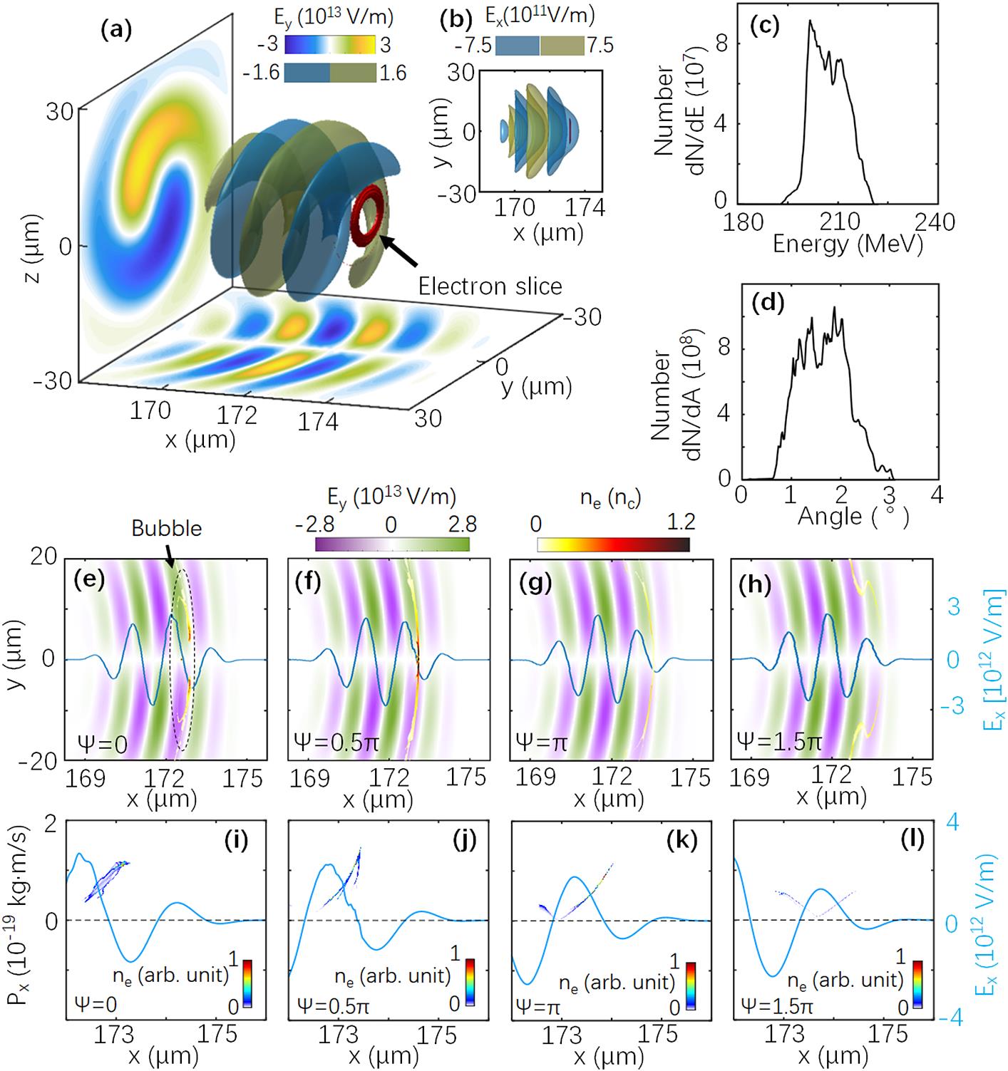
Figure 1.Electron slice and LG laser field in PIC simulation. (a) Sketch of an electron slice driven by an LG laser. The red donut indicates the isosurface of the electron slice with
Figures 1(e)–1(h) show that the density distribution shapes of the electron slices at t = 88T can be changed from disk to annulus by varying the CEP of the LG laser. For Ψ = 0, the density distribution of the electrons is modulated to an annular shape with an inner diameter of approximately 10 μm, as shown in Figures 1(a), 1(b), and 1(e). This annular electron slice can be accelerated up to 220 MeV with a slice thickness of 0.2 μm (corresponding to approximately 670 attoseconds) at t = 88T, as shown in Figure 1(e). The total charge of such an annular electron slice can reach up to approximately 0.19 nC. By contrast, an electron disk is generated at the beam center when Ψ = 0.5π, as shown in Figure 1(f). In the other two cases shown in Figures 1(g) and 1(h), the electron slice is dispersed. The electron motion seems to have a close relationship with the phase structure in the laser field.
To explain the effects of CEP on the formation of the annular electron slice (see Figures 1(a) and 1(e)), both the transverse (Figures 2(a)–2(d)) and longitudinal electric fields (Figure 2(e)) in one laser cycle are discussed. It should be noted that most electrons travel along the direction of the laser and the transverse electron field
![]()
Figure 2.Structure of electric fields of CP LG laser and phase-space distribution of electrons. Normalized vector plots of the transverse electric fields in one laser cycle for (a) point i, (b) point ii, (c) point iii, and (d) point iv marked in (e). (e) Normalized amplitude of
In the other two cases shown in Figures 1(k) and 1(l), the electrons are first dispersed by the transverse fields. Although they lie in the accelerating phase at the beginning of the interaction, the amplitude of Ex is much lower than in the cases shown in Figures 1(i) and 1(j). Therefore, these electrons will easily slide into the decelerating phase and undergo considerable dispersion in the longitudinal direction. Finally, fewer electrons are formed about the beam axis, much different from the cases shown in Figures 1(i) and 1(j). This indicates that the formation of a concentrated electron slice with high energy requires two conditions in our case. On the one hand, the transverse electric fields should be concentrated on the electrons at the beginning of the interaction. On the other hand, the electrons should move into the large and stable accelerating phase as soon as possible, so that they can remain in a concentrated state in the ensuing acceleration process. If the transverse rotating fields just lie in the accelerating phase, the annular electron slice can be successfully maintained, as shown in Figures 1(a) and 1(i).
3 Theoretical analysis
To explain the simulation results, a single-particle model is employed to show the dynamic motion of a single electron in the LG laser field. The fundamental motion of the electrons can be described by the equation
For the mode of CP
To understand the phase-locked movement of the electron slice in the PIC simulations, the single-particle model was applied for four typical electrons at x = 3.8 μm, y = ±1 μm, and z = ±1 μm, where the location of the simulation phase-locked region, shown in Figure 1(a), is considered. According to the angular distribution of electrons, the transverse velocity vr is much lower than vx (vr/vx < 3% for most electrons). The value vr = 0 is used for simplicity. The initial longitudinal velocity of the electrons is set to 0.999c, because the energy of most of the electrons that just enter the accelerating phase is approximately 11 MeV when vx = 0.999c at t = 42T in the simulations. The parameters of the electromagnetic field are the same as when Ψ = 0, as shown in Figure 1(e), in the PIC simulation. The 3D trajectories of the electrons show that they could remain in the acceleration phase of the CP LG laser for a distance more than 60 μm, as shown in Figure 3(a). It should be noted that the electron slice gains hundreds of megaelectronvolts of energy from such a phase-locked acceleration in the PIC simulation. In addition, the electrons undergo a right-handed rotation about the x axis (see Figure 3(c)), consistent with the vector distributions of the transverse electric fields in the accelerating phase (see Figure 2(d)). In PIC simulation, the direction of rotated transverse electric field does not change in the accelerating phase, so that the angular momentum (AM) of electrons can continually increase from negative to positive after t = 40T, just as shown in Figure 3(b). However, the initial AM of the electron is zero in the single-particle model. Thus, the total AM of the four electrons can only increase from zero to positive in accelerating phase, and the rotation directions of electrons do not change in Figure 3(c). We assume that the electrons can be rotated by these transverse electric fields (see Figure 2(b)), as evidenced by the evolution of their AM shown in Figure 3(b). Therein, the resonance of the AM corresponds to the different rotations (right-handed or left-handed) of the transverse electric fields (see Figures 2(b) and 2(d)).
![]()
Figure 3.Trajectories of electrons in a single-particle model and AM in PIC simulation. (a) 3D trajectories of electrons at different initial positions of
4 Discussion
From the analyses described here, we find that a near-infrared LG laser can successfully provide a stable and efficient accelerating phase to generate a single annular attosecond electron slice in the DLA regime. The main reason is that the near-infrared LG laser (λ = 2 μm) can provide a longer accelerating field to stably maintain the annular structure of the electrons up to 853 fs (see Figure 4(a)). It should be noted that a small part of the electron beam is dragged into the next accelerating field, and can be concentrated by the transverse electric field forming a small dot around the beam axis (x axis), just as shown in Figure 4(a). A clearer annular electron slice may be obtained if we set a solid target to stop the further acceleration of the LG laser in the earlier interacting progress. From Figure 4(a), the corresponding energy of the electron slice can be further accelerated from ∼210 MeV at 88T (see Fig. 1(c)) to ∼280 MeV at t = 128T (853 fs) (see Figure 4(d)). By contrast, the electron slices are considerably dispersed at 853 fs when the laser wavelength is shorter (λ = 800 nm), as shown in Figure 4(b), and the electrons can only be accelerated up to ∼80 MeV due to the easier dephasing effect for the LG laser with a shorter wavelength (see Figure 4(e)). More importantly, the angular divergence remains at ∼2° (see Figure 4(g)) over 88T, meaning that an electron slice can be well concentrated in the ‘bubble’, thus overcoming the dispersion problem in the DLA regime when driven by a conventional Gaussian laser pulse (see Figures 4(c) and 4(i)). Although, the maximum energy can also be accelerated up to ∼150 MeV at 853 fs when using a Gaussian laser with λ = 2 μm, the energetic spread is as high as ∼30% (see Figure 4(f)). In addition, the divergence of the electron slice is 0°–7° in the case of the LG laser with λ = 800 nm (see Figure 4(h)) and 3°–6° in the case of the Gaussian laser with λ = 2 μm (see Figure 4(i)), which is greater than that (∼2°) in the case of the near-infrared LG laser with λ = 2 μm (see Figure 4(g)). All these comparisons indicate that the near-infrared LG laser discussed in this article helps accelerate the electron slice to a higher energy (hundreds of megaelectronvolts) with attosecond duration and concentrate it in a smaller divergence angle (∼2°). Such high quality of the annular electron slice may have various applications, such as antiprotons in conventional linear accelerators[49], edge-enhancement electron imaging[50], structured X-ray generation[51], and analysis and manipulation of nanomaterials[52].
![]()
Figure 4.Comparisons between the cases driven by LG laser and Gaussian laser. Density distributions of electrons at
It should be noted that the longitudinal electric field (Ex) of the LG laser plays an important role in accelerating the electron slice to a high energy in the ‘bubble’ mechanism in this paper, where the charge-separation field between the electron and ion slice is not considered. It is reasonable because the normalized amplitude of the charge-separation field
5 Summary
In conclusion, a novel annular electron slice driven by a few-cycle near-infrared LG laser has been investigated for the first time through 3D PIC simulations. We have found that a near-infrared LG laser can provide a ‘bubble’ region, characterized by a longer longitudinal electric field that can stably accelerate the electron slice up to hundreds of megaelectronvolts with attosecond duration. The longitudinal field mainly accelerates or decelerates the electrons in the forward direction in our case. The disk or annular formation of the electron slice can be tuned by the transverse fields in LG laser. A stable formation of the annular electron slice needs a proper combination of the longitudinal and transverse fields with different amplitudes, which are just determined by the CEP of the LG laser. The annular attosecond electron slice is compact and may have potential applications in the collimation of energetic particles such as antiprotons in conventional linear accelerators, edge-enhancement electron imaging, structured X-ray generation, and analysis and manipulation of nanomaterials. It should be noted that Nie et al. recently presented a new method to obtain relativistic few-cycle-tunable infrared pulses from a tailored plasma density structure[61]. We believe that the relativistic near-infrared LG laser discussed in this article can also be implemented as a similar technology to ultimately generate annular attosecond electron slices in experiments in the future.
References
[1] D. Strickland, G. Mourou. Opt. Commun, 56, 219(1985).
[2] Y. X. Leng. Chin. J. Lasers, 46(2019).
[3] Z. Zhang, F. Wu, J. Hu, X. Yang, J. Gui, P. Ji, X. Liu, C. Wang, Y. Liu, X. Lu, Y. Xu, Y. Leng, R. Li, Z. Xu. High Power Laser Sci. Eng, 8(2020).
[4] F. Lureau, G. Matras, O. Chalus, C. Derycke, T. Morbieu, C. Radier, O. Casagrande, S. Laux, S. Ricaud, G. Rey, A. Pellegrina, C. Richard, L. Boudjemaa, C. Simon-Boisson, A. Baleanu, R. Banici, A. Gradinariu, C. Caldararu, B. D. Boisdeffre, P. Ghenuche, A. Naziru, G. Kolliopoulos, L. Neagu, R. Dabu, I. Dancus, D. Ursescu. High Power Laser Sci. Eng, 8(2020).
[5] M. Turner, E. Adli, A. Ahuja, O. Apsimon, R. Apsimon, A. M. Bachmann, M. Barros Marin, D. Barrientos, F. Batsch, J. Batkiewicz, J. Bauche, V. K. Berglyd Olsen, M. Bernardini, B. Biskup, A. Boccardi, T. Bogey, T. Bohl, C. Bracco, F. Braunmüller, S. Burger, G. Burt, S. Bustamante, B. Buttenschön, A. Caldwell, M. Cascella, J. Chappell, E. Chevallay, M. Chung, D. Cooke, H. Damerau, L. Deacon, L. H. Deubner, A. Dexter, S. Doebert, J. Farmer, V. N. Fedosseev, G. Fior, R. Fiorito, R. A. Fonseca, F. Friebel, L. Garolfi, S. Gessner, I. Gorgisyan, A. A. Gorn, E. Granados, O. Grulke, E. Gschwendtner, A. Guerrero, J. Hansen, A. Helm, J. R. Henderson, C. Hessler, W. Hofle, M. Hüther, M. Ibison, L. Jensen, S. Jolly, F. Keeble, S. Y. Kim, F. Kraus, T. Lefevre, G. LeGodec, Y. Li, S. Liu, N. Lopes, K. V. Lotov, L. Maricalva Brun, M. Martyanov, S. Mazzoni, D. Medina Godoy, V. A. Minakov, J. Mitchell, J. C. Molendijk, R. Mompo, J. T. Moody, M. Moreira, P. Muggli, E. Öz, E. Ozturk, C. Mutin, C. Pasquino, A. Pardons, F. Peña Asmus, K. Pepitone, A. Perera, A. Petrenko, S. Pitman, G. Plyushchev, A. Pukhov, S. Rey, K. Rieger, H. Ruhl, J. S. Schmidt, I. A. Shalimova, E. Shaposhnikova, P. Sherwood, L. O. Silva, L. Soby, A. P. Sosedkin, R. Speroni, R. I. Spitsyn, P. V. Tuev, F. Velotti, L. Verra, V. A. Verzilov, J. Vieira, H. Vincke, C. P. Welsch, B. Williamson, M. Wing, B. Woolley, G. Xia. Phys. Rev. Lett, 122, 054801(2019).
[6] J. Ren, C. Maurer, P. Katrik, P. M. Lang, A. A. Golubev, V. Mintsev, Y. Zhao, D. H. H. Hoffmann. Contrib. Plasma Phys, 58, 82(2018).
[7] M. Thévenet, A. Leblanc, S. Kahaly, H. Vincenti, A. Vernier, F. Quéré, J. Faure. Nat. Phys, 12, 355(2015).
[8] C. Joshi, W. B. Mori, T. Katsouleas, J. M. Dawson, J. M. Kindel, D. W. Forslund. Nature, 311, 525(1984).
[9] S. P. Mangles, C. D. Murphy, Z. Najmudin, A. G. Thomas, J. L. Collier, A. E. Dangor, E. J. Divall, P. S. Foster, J. G. Gallacher, C. J. Hooker, D. A. Jaroszynski, A. J. Langley, W. B. Mori, P. A. Norreys, F. S. Tsung, R. Viskup, B. R. Walton, K. Krushelnick. Nature, 431, 535(2004).
[10] J. Faure, Y. Glinec, A. Pukhov, S. Kiselev, S. Gordienko, E. Lefebvre, J. P. Rousseau, F. Burgy, V. Malka. Nature, 431, 541(2004).
[11] C. G. Geddes, C. S. Toth, J. Van Tilborg, E. Esarey, C. B. Schroeder, D. Bruhwiler, C. Nieter, J. Cary, W. P. Leemans. Nature, 431, 538(2004).
[12] E. Esarey, C. B. Schroeder, W. P. Leemans. Rev. Mod. Phys, 81, 1229(2009).
[13] X. Wang, R. Zgadzaj, N. Fazel, Z. Li, S. A. Yi, X. Zhang, W. Henderson, Y. Y. Chang, R. Korzekwa, H. E. Tsai, C. H. Pai, H. Quevedo, G. Dyer, E. Gaul, M. Martinez, A. C. Bernstein, T. Borger, M. Spinks, M. Donovan, V. Khudik, G. Shvets, T. Ditmire, M. C. Downer. Nat. Commun, 4, 1988(2013).
[14] W. P. Leemans, A. J. Gonsalves, H. S. Mao, K. Nakamura, C. Benedetti, C. B. Schroeder, C. Toth, J. Daniels, D. E. Mittelberger, S. S. Bulanov, J. L. Vay, C. G. Geddes, E. Esarey. Phys. Rev. Lett, 113, 245002(2014).
[15] A. J. Gonsalves, K. Nakamura, J. Daniels, C. Benedetti, C. Pieronek, T. C. H. de Raadt, S. Steinke, J. H. Bin, S. S. Bulanov, J. van Tilborg, C. G. R. Geddes, C. B. Schroeder, C. Tóth, E. Esarey, K. Swanson, L. Fan-Chiang, G. Bagdasarov, N. Bobrova, V. Gasilov, G. Korn, P. Sasorov, W. P. Leemans. Phys. Rev. Lett, 122, 084801(2019).
[16] F. V. Hartemann, S. N. Fochs, G. P. Le Sage, N. C. Luhmann, J. G. Woodworth, M. D. Perry, Y. J. Chen, A. K. Kerman. Phys. Rev. E, 51, 4833(1995).
[17] A. Maltsev, T. Ditmire. Phys. Rev. Lett, 90, 053002(2003).
[18] X. Cai, J. Zhao, Q. Lin, H. Tong, J. Liu. Opt. Express, 26, 30030(2018).
[19] A. Denoeud, L. Chopineau, A. Leblanc, F. Quere. Phys. Rev. Lett, 118, 033902(2017).
[20] X.-M. Cai, J.-Y. Zhao, Q. Lin, J.-L. Luo. J. Opt. Soc. Am. B, 33, 158(2016).
[21] Y. I. Salamin, C. H. Keitel. Phys. Rev. Lett, 88, 095005(2002).
[22] M. C. Downer, R. Zgadzaj, A. Debus, U. Schramm, M. C. Kaluza. Rev. Mod. Phys, 90, 035002(2018).
[23] J. Schreiber, P. R. Bolton, K. Parodi. Rev. Sci. Instrum, 87, 071101(2016).
[24] W. Wang, B. Shen, X. Zhang, L. Zhang, Y. Shi, Z. Xu. Sci. Rep, 5, 8274(2015).
[25] X. Wang, B. Shen, X. Zhang, W. Wang, J. Xu, L. Yi, Y. Shi. Phys. Plasmas, 22, 043106(2015).
[26] W. P. Wang, C. Jiang, H. Dong, X. M. Lu, J. F. Li, R. J. Xu, Y. J. Sun, L. H. Yu, Z. Guo, X. Y. Liang, Y. X. Leng, R. X. Li, Z. Z. Xu. Phys. Rev. Lett, 125, 034801(2020).
[27] X. Zhang, B. Shen, L. Zhang, J. Xu, X. Wang, W. Wang, L. Yi, Y. Shi. New J. Phys, 16, 123051(2014).
[28] J. Vieira, J. T. Mendonca, F. Quere. Phys. Rev. Lett, 121, 054801(2018).
[29] L. X. Hu, T. P. Yu, Z. M. Sheng, J. Vieira, D. B. Zou, Y. Yin, P. McKenna, F. Q. Shao. Sci. Rep, 8, 7282(2018).
[30] C. Baumann, A. Pukhov. Phys. Plasmas, 25, 083114(2018).
[31] L. B. Ju, C. T. Zhou, K. Jiang, T. W. Huang, H. Zhang, T. X. Cai, J. M. Cao, B. Qiao, S. C. Ruan. New J. Phys, 20, 063004(2018).
[32] L.-X. Hu, T.-P. Yu, Y. Lu, G.-B. Zhang, D.-B. Zou, H. Zhang, Z.-Y. Ge, Y. Yin, F.-Q. Shao. Plasma Phys. Control. Fusion, 61, 025009(2019).
[33] J. Vieira, J. T. Mendonça. Phys. Rev. Lett, 112, 215001(2014).
[34] H. He, M. E. Friese, N. R. Heckenberg, H. Rubinsztein-Dunlop. Phys. Rev. Lett, 75, 826(1995).
[35] L. Allen, M. Beijersbergen, R. Spreeuw, J. Woerdman. Phys. Rev. A, 45, 8185(1992).
[36] N. V. Zamfir. Eur. Phys. J. Spec. Top, 223, 1221(2014).
[37] Y. Shi, B. Shen, L. Zhang, X. Zhang, W. Wang, Z. Xu. Phys. Rev. Lett, 112, 235001(2014).
[38] W. Gong, B. Shen, L. Zhang, X. Zhang. New J. Phys, 21, 043022(2019).
[39] A. Leblanc, A. Denoeud, L. Chopineau, G. Mennerat, P. Martin, F. Quéré. Nat. Phys, 13, 440(2017).
[40] R. Nuter, P. Korneev, I. Thiele, V. Tikhonchuk. Phys. Rev. E, 98, 033211(2018).
[41] J. Vieira, R. M. Trines, E. P. Alves, R. A. Fonseca, J. T. Mendonca, R. Bingham, P. Norreys, L. O. Silva. Nature, 7, 10371(2016).
[42] S. Haddadi, O. Bouzid, M. Fromager, A. Hasnaoui, A. Harfouche, E. Cagniot, A. Forbes, K. Aït-Ameur. J. Opt, 20, 045602(2018).
[43] A. Pukhov, J. Meyer-ter-Vehn. Appl. Phys. B, 74, 355(2002).
[44] M. Chen, Z.-M. Sheng, Y.-Y. Ma, J. Zhang. J. Appl. Phys, 99, 056109(2006).
[45] T. M. Jeong, S. Bulanov, W. Yan, S. Weber, G. Korn. OSA Continuum, 2, 2718(2019).
[46] W. P. Wang, C. Jiang, B. F. Shen, F. Yuan, Z. M. Gan, H. Zhang, S. H. Zhai, Z. Z. Xu. Phys. Rev. Lett, 122, 024801(2019).
[47] X. Zhang, B. Shen, Y. Shi, X. Wang, L. Zhang, W. Wang, J. Xu, L. Yi, Z. Xu. Phys. Rev. Lett, 114, 173901(2015).
[48] S. Li, B. Shen, X. Zhang, Z. Bu, W. Gong. Opt. Express, 26, 23460(2018).
[49] G. Stancari, A. Valishev, G. Annala, G. Kuznetsov, V. Shiltsev, D. A. Still, L. G. Vorobiev. Phys. Rev. Lett, 107, 084802(2011).
[50] C. J. Zhang, J. F. Hua, Y. Wan, C. H. Pai, B. Guo, J. Zhang, Y. Ma, F. Li, Y. P. Wu, H. H. Chu, Y. Q. Gu, X. L. Xu, W. B. Mori, C. Joshi, J. Wang, W. Lu. Phys. Rev. Lett, 119, 064801(2017).
[51] T. Z. Zhao, K. Behm, C. F. Dong, X. Davoine, S. Y. Kalmykov, V. Petrov, V. Chvykov, P. Cummings, B. Hou, A. Maksimchuk, J. A. Nees, V. Yanovsky, A. G. Thomas, K. Krushelnick. Phys. Rev. Lett, 117, 094801(2016).
[52] M. Mousley, G. Thirunavukkarasu, M. Babiker, J. Yuan. Proc. SPIE, 9581, 95810C(2015).
[53] T. D. Arber, K. Bennett, C. S. Brady, A. Lawrence-Douglas, M. G. Ramsay, N. J. Sircombe, P. Gillies, R. G. Evans, H. Schmitz, A. R. Bell, C. P. Ridgers. Plasma Phys. Control. Fusion, 57, 113001(2015).
[54] A. Henig, S. Steinke, M. Schnurer, T. Sokollik, R. Horlein, D. Kiefer, D. Jung, J. Schreiber, B. M. Hegelich, X. Q. Yan, J. Meyer-ter-Vehn, T. Tajima, P. V. Nickles, W. Sandner, D. Habs. Phys. Rev. Lett, 103, 245003(2009).
[55] J. H. Bin, W. J. Ma, H. Y. Wang, M. J. Streeter, C. Kreuzer, D. Kiefer, M. Yeung, S. Cousens, P. S. Foster, B. Dromey, X. Q. Yan, R. Ramis, J. Meyer-ter-Vehn, M. Zepf, J. Schreiber. Phys. Rev. Lett, 115, 064801(2015).
[56] W. P. Wang, B. F. Shen, Z. Z. Xu. Phys. Plasmas, 24, 013104(2017).
[57] W. P. Wang, B. F. Shen, X. M. Zhang, L. L. Ji, Y. H. Yu, L. Q. Yi, X. F. Wang, Z. Z. Xu. Phys. Rev. ST Accel. Beams, 15, 081302(2012).
[58] W. P. Wang, B. F. Shen, X. M. Zhang, L. L. Ji, M. Wen, J. C. Xu, Y. H. Yu, Y. L. Li, Z. Z. Xu. Phys. Plasmas, 18, 013103(2011).
[59] W. Wang, C. Jiang, S. Li, H. Dong, B. Shen, Y. Leng, R. Li, Z. Xu. High Power Laser Sci. Eng, 7, e55(2019).
[60] Q. Zhan. Opt. Lett, 31, 867(2006).
[61] Z. Nie, C.-H. Pai, J. Hua, C. Zhang, Y. Wu, Y. Wan, F. Li, J. Zhang, Z. Cheng, Q. Su, S. Liu, Y. Ma, X. Ning, Y. He, W. Lu, H.-H. Chu, J. Wang, W. B. Mori, C. Joshi. Nat. Photonics, 12, 489(2018).


Set citation alerts for the article
Please enter your email address

© Copyright 2018-2021 | Chinese Laser Press. All Rights Reserved 沪ICP备15018463号-20