V. A. Gribkov1,2, I. V. Borovitskaya1, E. V. Demina1, E. E. Kazilin1..., S. V. Latyshev1,3, S. A. Maslyaev1, V. N. Pimenov1,2, T. Laas2,4, M. Paduch2,5 and S. V. Rogozhkin6|Show fewer author(s)
1A.A. Baikov Institute of Metallurgy and Material Science, RAS, Leninsky Prospect 49, 119991 Moscow, Russian Federation
2The International Centre for Dense Magnetized Plasmas, ul. Hery 23, 01-497 Warsaw, Poland
3Moscow Technical University of Communications and Informatics, ul. Aviamotornaya 8а, 111024 Moscow, Russian Federation
4School of Natural Sciences and Health, Tallinn University, Narva Road 25, Tallinn 10120, Estonia
5The Institute of Plasma Physics and Laser Microfusion, ul. Hery 23, 01-497 Warsaw, Poland
6A.I. Alikhanov Institute for Theoretical and Experimental Physics of NRC “Kurchatov Institute”, ul. Bolshaya Cheremushkinskaya 25, 117218 Moscow, Russian Federation
V. A. Gribkov, I. V. Borovitskaya, E. V. Demina, E. E. Kazilin, S. V. Latyshev, S. A. Maslyaev, V. N. Pimenov, T. Laas, M. Paduch, S. V. Rogozhkin. Application of dense plasma focus devices and lasers in the radiation material sciences for the goals of inertial fusion beyond ignition[J]. Matter and Radiation at Extremes, 2020, 5(4): 045403
Copy Citation Text
Specimens of materials for prospective use in chambers of nuclear fusion reactors with inertial plasma confinement, namely, W, ODS steels, Eurofer 97 steel, a number of ceramics, etc., have been irradiated by dense plasma focus devices and a laser in the Q-switched mode of operation with a wide range of parameters, including some that noticeably exceeded those expected in reactors. By means of 1-ns laser interferometry and neutron measurements, the characteristics of plasma streams and fast ion beams, as well as the dynamics of their interaction with solid-state targets, have been investigated. 3D profilometry, optical and scanning electron microscopy, atomic emission spectroscopy, X-ray elemental and structural analyses, and precise weighing of specimens before and after irradiation have provided data on the roughening threshold and the susceptibility to damage of the materials under investigation. Analysis of the results, together with numerical modeling, has revealed the important role of shock waves in the damage processes. It has been shown that a so-called integral damage factor may be used only within restricted ranges of the irradiation parameters. It has also been found that in the irradiation regime with well-developed gasdynamic motion of secondary plasma, the overall amount of radiation energy is spent preferentially either on removing large masses of cool matter from the material surface or on heating a small amount of plasma to high temperature (and, consequently, imparting to it a high velocity), depending on the power flux density and characteristics of the pulsed irradiation.
I. INTRODUCTION
Radiation resistance of materials intended for the plasma-facing components (PFCs) of the chambers of nuclear fusion reactors (NFRs) with inertial plasma confinement (IPC) is an important current area of fusion research, since this resistance is essential for successful operation of future reactors of this type. PFCs are subjected to the effects of powerful and very short-pulsed blasts, and therefore, it is necessary to develop and test new types of materials that are able to withstand these conditions, with the help of appropriate simulations of IPC in NFRs.
In the context of nuclear fusion with magnetic plasma confinement (MPC) (see Ref. 1 and references therein), investigations of the corresponding problem have been carried out for several decades (see, e.g., the various Proceedings of the Symposia on Fusion Technology and of the International Conferences on Fusion Reactor Materials). In the testing of candidate materials for NFRs with MPC, quasi-stationary plasma accelerators such as QSPA Kh-50,2,3 QSPA-T,4 and PSI,5 plasma guns,6 and electron-beam heating7 have been employed to simulate the situations in tokamaks. Heat loads are usually produced in these simulators by directed plasma streams and electron beams (thus, irradiating relatively small areas of specimens), with pulse durations ranging from a hundred microseconds to seconds. Powerful lasers operating in a free-running mode with a sequence of hundreds of pulses each 1 µs long and lasting for a total of approximately 0.1 ms can successfully simulate emergency phenomena in tokamaks, such as sawtooth instability (STI) and edge-localized modes (ELMs).8
As far as the second approach to nuclear fusion, namely, NFRs with IPC,9,10 is concerned, there is much less published work on radiation resistance of PFC materials. To date, most tests on these materials have used soft X rays (see, e.g., Refs. 11 and 12). However, X rays are only one source of radiation damage to chambers such as those of the National Ignition Facility (NIF)9 and the Z Machine,10,12 and in fact are not the most dangerous type.
The greatest threat to PFC materials in both types of NFR comes from streams of fast ions (FIS; see, e.g., Ref. 13). This is because of the considerable amount of energy that they carry during NFR operation, their short range of penetration in solid or liquid matter, the absence of a so-called “detachment” effect (which is so important for plasma irradiation), and their specific absorption mechanism with a characteristic Bragg peak at the end of their penetration path.14 These factors result in a very high density of energy release in the bulk of irradiated material. Despite the importance of FIS, however, sources of powerful beams of fast ions such as the RHEPP-1 accelerator (Sandia National Laboratories)15 have very rarely been used in experiments simulating damage to PFC materials.
Numerical modelling of the conditions in the NIF chamber for a direct-drive scheme and experiments performed in the hohlraum “high-foot” regime have shown that the distribution of the total of about 150 MJ of fusion energy released9,15 is distributed among several channels (X-rays, ion and plasma streams, and neutrons) that irradiate the chamber walls.
For FIS illuminating PFCs in the NIF (about 30% of the overall energy released), the individual energy of quasiparticles Ei, the efficiency of the energy stream η, the power flux density of the irradiation stream on the target surface (i.e., on the chamber wall) P, the absorbed dose D, and the pulse duration τ expected (and already realized partially) are as follows (the NIF chamber radius is 6.5 m):9,10,15
Ei ≤ a few MeV, η ∼ 30%, for ions of fusion origin: P ∼ 109 W/cm2, D ∼ 20 J/cm2, and τ ≤ 10 ns;
Ei ≤ a few MeV, η ∼ 30%, for ions of fusion origin: P ≤ 108 W/cm2, D ∼ 20 J/cm2, and τ ≤ 0.5 µs;
for Ei ≤ 0.5 MeV, η ∼ 30%, for low-energy ions in the plasma formed from target debris plus ions accelerated by laser–plasma interaction: P ≤ 108 W/cm2, D ≤ 20 J/cm2, and τ ≤ 3 µs.
It can be seen from these data that IPC reactors differ from MPC reactors1,2 in that the ion streams irradiating PFC in the former have much shorter pulse durations τ and noticeably higher power flux densities P.
At first sight, the integral damage factor (IDF)16,17 (sometimes called the heat flux factor), given by F = (PD)0.5 = Pτ0.5, may be a useful quantity for estimating the conditions on the first wall of an NFR with IPC when a long-pulse facility2–7 is used for simulation.
Indeed, the short pulse durations in an NFR with IPC (which are in the range from 10−9–10−6 s) may seem to be compensated by the much higher energy available in long-pulsed high-power devices, and the values of Ftok = 108 × (10−4)0.5 = 106 W s0.5/cm2 for tokamaks and the corresponding simulators1–8 and of FIPC = 1010 × (10−8)0.5 = 106 W s0.5/cm2 for NFRs with IPC9,10 might appear to be the same. However an analysis of the relevant conditions shows that the situation is not so simple.
Generally speaking, in the various ranges of individual energies Ei of ions irradiating a target at low stream intensities, the following interaction processes will take place with the target material:
10−2–101 eV: thermal activation;
10−1–103 eV: desorption;
101–105 eV: sputtering;
102–107 eV: implantation.
If the power flux density of radiation P for particles having energy Ei above 102 eV (i.e., higher than the ionization potential) is successively increased from the implantation level of P > 102 W/cm2 to about 1012 W/cm2 and above, the radiation will have the following effects on the target material:
implantation, i.e., an low-temperature process by which individual ions of a given element are injected into the solid material, thereby changing its physical, chemical, or electrical properties without heating it;
heating of the target material, together with roughening, embrittlement, and cracking.
melting, with spattering and droplet formation;
evaporation, with droplet spraying;
ablation of various types;
first stage of ionization of evaporated material;
second stage of ionization, …
The last three stages may be accompanied by the formation of shock waves (SWs) generated inside the irradiated target. At each stage except the first, as well as the energy expended in heating the material, some of the irradiation energy will be expended in increasing the entropy (a measure of the “devaluation of energy”) of the system—the latent heat of melting and the latent heat of evaporation—for sublimation of material (ablation), for successive stages of ionization of secondary plasma particles, for the formation of SWs, whose energy is subsequently dissipated in the bulk of the material, etc. Thus, not all of the energy (dose) of irradiation will be transformed into various forms of damage to the surface and thin subsurface layers of the target. This means that the IDF is relevant only for restricted ranges of dose or power flux density, and each case must be carefully analyzed on an individual basis.
Thus, the best situation for material testing is to use the heating methods with parameters (heat carriers and the associated individual particle energy E, dose D, power flux density P and pulse duration τ, region and mechanism of absorption, etc.) that are as close as possible to those (see, e.g., Ref. 18) that occur in real NFRs of the each type.
It should be noted that in NFRs with MCF, the conditions considered here are those associated with transients such as edge-localized modes (ELMs) or disruptions, whereas in the case of ICF, they reflect the normal operation of the facility. This means that for simulating plasma/ion bombardment fluxes in tests of materials intended for chambers with IPC, one has to use different machines from those used previously in the experiments on materials designed for PFCs of NFRs with MPC.2–7
Dense plasma focus (DPF) devices19 are able to generate directed cumulative high-speed (vpl ≥ 107 cm/s) and dense (npl∼ 1018 cm−3) flows of hot plasma (HP), streams of fast (Ei ≥ 100 keV to a few MeV) deuterons and tritons, fast ions of a number of materials (FIS), relativistic electrons (Ee ≥ 100–1000 keV), and soft and hard X-ray and neutron radiation, with short (tens of nanoseconds) powerful pulses. The typical power flux densities on the surface of a target placed inside a DPF chamber are in the range Ppl ∼ 104–1010 W/cm2 for HP flows and PFIS ∼ 106–1013 W/cm2 for FIS.
From a comparison of these heat and ion flux loads expected at the interaction of the streams with the PFC of an NFR with IPC, it can be seen that DPF facilities are very suitable for testing new materials for use in this type of NFR.
Measurements using activation and time-of-flight (TOF) techniques have shown that compact neutron sources based on medium-sized DPF devices (like Vikhr’ and PF-6) are able to generate neutron intensities of ∼109n per pulse of duration ∼10−8 s for a pure deuterium working gas or about 1011n per ∼10−8 s pulse for a deuterium–tritium mixture, which correspond to 1017 and 1019n/s, respectively. On the surfaces of the compact chambers used in medium-sized DPF devices (with overall chamber areas of about 4πR2 ≈ 10−1 m2), the neutron wall loading is in the range 0.1–100 MW/m2, depending on the working gas used (D2 or a D–T mixture). These figures are expected on the chamber walls of NFRs with IPC in the near future.
Facility safety issues with compact short-pulsed neutron sources based on medium-sized DPF devices with the above-mentioned neutron pulse parameters have been analyzed many times in various environments and for various regimes of DPF operation. It has been shown that at a repetition rate of about 1000 shots per day, the dose received by personnel does not exceed the permissible level at a distance R ≥ 10 m from the source in the absence of protective screens. This is safe enough for examination (taxonomy) of modern large-sized nuclear fusion chambers of NFRs with IPC under irradiation by neutron fluxes at the above-mentioned levels.
Solid-state Nd-glass lasers operating in the Q-switched (QS) mode may also provide heating for targets with the same power flux density and pulse duration of laser radiation (LR). This type of irradiation is of additional interest because in the NIF, LR is used as the target driver. Thus, these devices can also be used for tests of prospective materials intended for chambers of NFRs such as NIF and the Z Machine with the appropriate parameters for the heating streams.
In this context, it is important to investigate the physical processes taking place during the interactions of streams of plasma and fast ions with various targets over a wide range of power flux densities and to compare the results with those obtained for the interaction of LR with the same materials.
In general, radiation test experiments are of two types: (i) those intended to find conditions under which the first-wall materials remain unaffected and (ii) those intended to investigate different types of damage produced in environments that are similar to or even harsher than those expected during the most severe events in NFRs with IPC. Our experiments described here are of the second type.
II. DEVICES
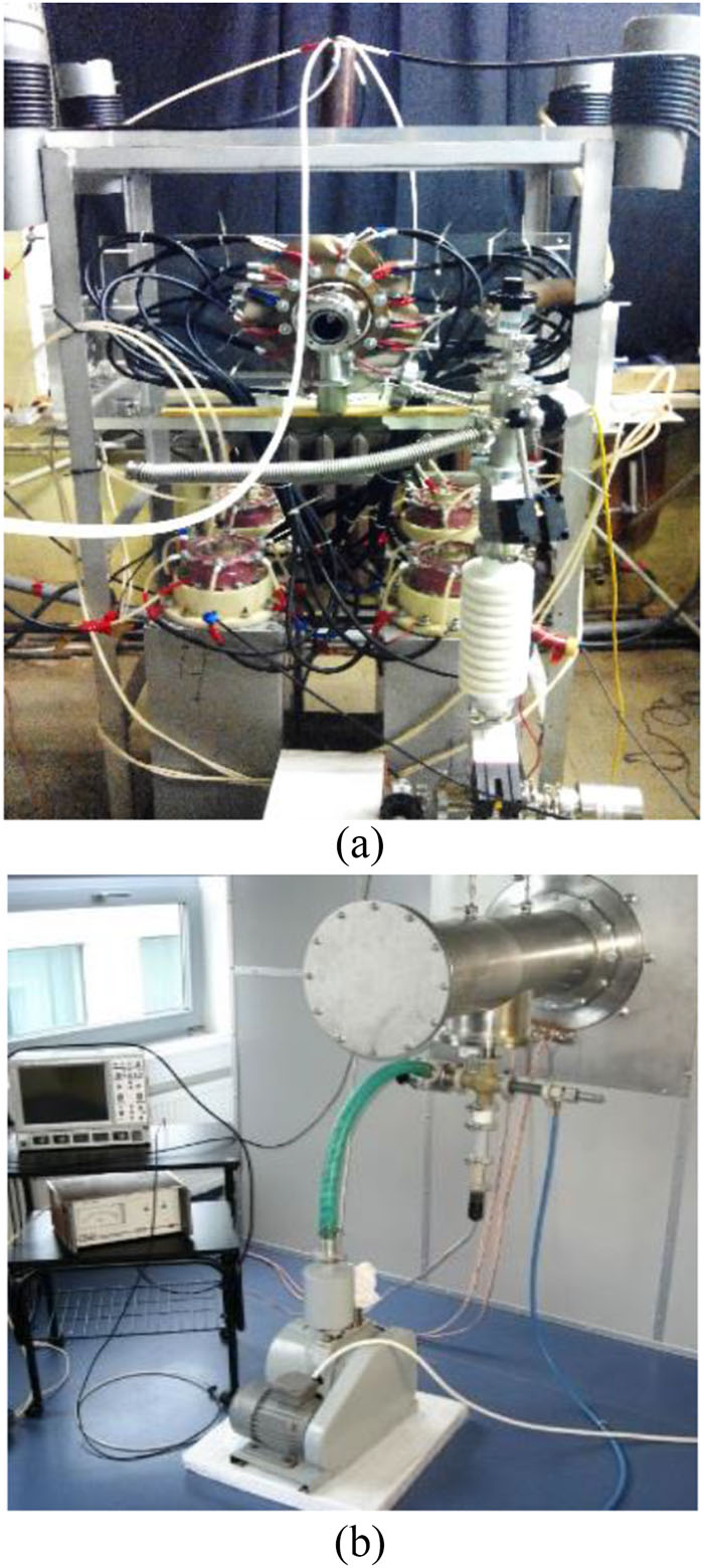
In our experiments on material testing, we used DPF devices,20–23 as well as a Nd-glass laser working in the QS mode.8 The DPF installations were Vikhr’ (2–5 kJ) and PF-5M (2 kJ) (both at IMET RAS, Russian Federation), PF-12 (3–6 kJ) (at TU, Estonia), and PF-6 (3–7 kJ) and the large facility PF-1000U (0.2–1.0 MJ) (both at IPPLM, Poland).
The first four, relatively small, devices are capable of working at repetition rates up to 2 Hz with deuterium and with other working gases. The 1-MJ installation can produce shots every 20 min. The typical power flux densities in the DPF devices were in the ranges Ppl ∼ 104–1010 W/cm2 for plasma streams and PFIS ∼ 106–1013 W/cm2 for fast ion fluxes. That is, at their upper levels, they noticeably exceeded the above-mentioned figures calculated and reached for the PFCs in contemporary mainstream NFRs with IPC. The Nd-glass laser that we used generated 50-ns pulses with a power flux density in the focal spot of up to 1012 W/cm2.
These devices have been used previously8,23–28 for testing materials, mostly with the power flux densities of the deuterium HP and FIS at the DPF and with the Nd-glass laser operating below 1011 W/cm2. In this paper, the results of the experiments and the corresponding numerical simulations will be presented for the regimes where the above-mentioned facilities have been used with a wide range of parameters, including some that have considerably exceeded the upper levels expected in the above reactors, namely, with P = 1011–1012 W/cm2. Results will also be presented for irradiation of other materials that have been considered for possible use in the PFCs of NFRs with IPC in these modes of operation.
The investigations proceeded as follows. First, the damage to various materials produced by HP and FIS from DPF devices was investigated. Second, these effects were compared with those of laser light produced in the QS mode with similar short pulse duration and power flux density. During these tests, the DPF devices20,22,23 (Figs. 1 and 2) were operated mainly at energy levels of ≤3 kJ, except for the PF-1000U facility21 (Figs. 3 and 4), which was operated in the range 160–400 kJ. All the DPF devices used deuterium as working gas.
In a course of the irradiation experiments, a number of important parameters, including the temporal and spatial evolutions of the density of the primary plasma (belonging to the DPF pinch and the cumulating plasma streams), the power flux characteristics of the fast ion and relativistic electron beams irradiating the targets, and soft and hard X-ray and neutron radiation and their angular and spatial distributions, can be monitored with high temporal, spatial, and spectral resolutions. Various phenomena produced by plasma streams and FIS on the surfaces of solid targets and in the bulk of materials under test can also be observed.
Figure 2 shows a tungsten specimen fixed in a holder that can be attached to the lids of special DPF chambers of the PF-6 and Vikhr’ devices. This assemblage was used in the experiments for testing the effects on various materials of plasma streams and FIS generated in the device.
Figure 4 shows the target’s assemblage placed in the cathode part of the PF-1000U facility. During some tests, the PF-1000U facility used a modified anode with a conical central insert intended to improve plasma stream formation.
The anodes of all the devices have holes in the center. These orifices prevent the powerful relativistic electron beam from evaporating the anode material (copper).
During operation of the DPF devices, the following parameters were monitored: the current derivative (with respect to time) by magnetic probes, the full discharge current by a Rogowski coil, and neutron and X-ray pulses by six photomultiplier tubes with scintillators (PMT+S) (the time resolution of this last technique was ≈2 ns). Plasma dynamics visualization was provided by time-integrated photography in the visual range, by 1-ns four-frame self-luminescence registration, and by 16-frame laser interferometry (1 ns for each frame with time intervals of 20 ns or 30 ns between them). The absolute neutron yield was monitored using Ag, In, Y, and Be activation counters.
After a number of conditioning discharges of the DPF devices, they started to generate neutrons and hard X rays. Measurement of the current derivative of a discharge and of absolute neutron yield generated by the device gave data on the strength of the particular discharge (“shot”).
Usually the current derivative is measured by a magnetic probe, whereas the neutron yield in a DPF is determined by two methods, namely, from data obtained with activation counters and by examination of oscilloscope traces of a time-resolved fast probe. The “quality” of the discharge and the power of the ion beam in each DPF device were estimated from the sharpness and amplitude of the current derivative peak on oscilloscope traces (Fig. 5) as well as from the amplitude of the corresponding neutron flash (Fig. 6) plus the absolute neutron yield measured by activation techniques.
Figure 5.Oscilloscope traces of the current derivatives of the discharges produced at the PF-6 device: (a) a “bad” shot; (b) a “good” shot.
Figure 6.PMT+S oscilloscope traces of discharges produced at the PF-6 device, with generation of hard X rays (X) and neutrons (n): (a) a “bad” shot; (b) a “good” shot.
A single-cascade laser device, GOS-1001,8 with a flat resonator (Fig. 7) capable of working in the QS mode (ensuring values of P = 109–1012 W/cm2, τ = 50 ns) was used for heating of targets by LR in the regime with parameters close to those typical of the FIS generated in the PF-6 and Vikhr’ devices.
Figure 7.GOS-1001 laser device capable of working with a pulse of about 50 ns and 20 J in the Q-switched mode.
III. MATERIALS, IRRADIATION CONDITIONS, AND ANALYSIS TECHNIQUES
At present, it is rather difficult to make a final choice in favor of a preferred material for use in the PFCs of NFRs with IPC. This is because the interactions of FIS and LR with chamber walls under the conditions within these reactors are not completely known (see some results on this point later in this paper). An intensive search for new materials is in progress. The types of material that must be tested for reliable and efficient implementation in inertial nuclear fusion chambers include both conventional (solid metallic) materials and liquid metals used as an alternative PFC concept. All such material must be able to withstand high power loads at high wall temperatures. The aim of the tests is to find materials that are resistant to heating by powerful short-pulse heat and particle loads, that have long lifetimes (exhibiting endurance under erosion and material mixing, as well as retention of stable surface morphology), and that allow safe operations (with regard to fuel retention and removal, material migration, and dust formation).
The list of candidate materials includes the following: tungsten and other highly refractory metals (e.g., Mo and V), their alloys and coatings, high-entropy alloys (e.g., FeNiMnCr, WTaVCr, VCrTi, and VCrTiY), reduced-activation ferritic–martensitic (RAFM) steels, oxide-dispersion-strengthened ferritic or ferritic–martensitic steels and other metals reinforced by TiO2, ZnO, Nb2O5, and CuO (ODS steels), and various ceramics [e.g., carbon fiber composites (CFCs), SiC, and Al2O3]. Nanostructured W and SiC (as a tritium barrier and an anticorrosion cover), diamond-like carbon (DLC), N3Ti, AISI 316L and ASP 30 steels, W with 25% Re (W25Re), and 1% TiC in W (W–TiC) are also under intensive testing at present.
As optical materials tested for use in the first wall (windows for laser beams and for diagnostics, i.e., in the final optics), quartz, synthetic diamonds, sapphire and leucosapphire (Al2O3), CaF2, MgF2, KS-4V glass, and various multilayer nanoparticle armoring materials have been examined.
Candidate wet materials with a thin liquid layer or with thick liquid protection for sweating walls of NFRs include Pb, Li17Pb83 eutectics, Li2BeF4, and alloys of the type 01 420 Al–Mg–Li.
A variety of dissimilar materials for application in the construction of NFRs (Al, Ti, ceramics, etc.) also have to be examined under direct irradiation because their exposure to high energy loads could lead to possible damage or even to PFCs inside the NFR chamber becoming detached.
In this study, the materials under test were as follows:
double-forged tungsten;29
ODS steel: Fe–15Cr–4Al–2W–0.35Y2O3 ferritic steel KP4-ODS (Kyoto University) (which is thus different from the Fe–16Cr–4Al–2W–0.3Ti–0.3Y2O3 ODS steel investigated in Ref. 27);
Eurofer 97 stainless steel;
V–10Ti–6Cr alloy;
several types of specialized ceramics.
These materials are all considered to show promise for use in the PFCs of NFRs with IPC because of their good resistance to radiation and to shock-like impacts.
As mentioned above, DPF devices are particularly suitable for experimental tests of materials for use in NFRs with IPC because these devices can generate directed streams of particles with energies (individual ion energies in the range 1.0 keV to a few MeV) and power flux densities (P ∼ 106–1012 W/cm2) similar to those observed on the chamber walls of such NFRs. The laser pulses of the GOS-1001 device used in its QS mode can also simulate conditions occurring in NFRs with IPC. However, because the mechanisms and zones of absorption of laser energy and of particle streams from DPF devices are different, it is important to compare the results of irradiation of materials by these two types of beams (LR and HP/FIS) with similar parameters.
In the tests in the DPFs described here, the specimens were usually placed on the Z axis of the DPF chamber with their flat surface perpendicular to this axis at various distances from the DPF anode (see the photographs in Figs. 2 and 4 and the diagram in Fig. 8). In the PF-1000U and PF-12 facilities, these distances were 7 cm, 11.5 cm, 30 cm, and 50 cm, whereas in the PF-6 and Vikhr’ devices, they ranged from 3.4 cm to 18 cm.
Figure 8.Schematic of a hot plasma stream with a shock wave pushing past it and fast ion streams spreading into space from the DPF anode and irradiating targets placed at two positions (1 and 2).
The minimum distance from anode to specimen ensures almost the same maximum power flux density in all DPF devices, although in the medium-sized DPFs, this is spread over a much smaller area. The specimen holders were constructed in such a way that the specimen surface was maximally protected from any redeposition of holder material (Figs. 2 and 4). Each specimen was subjected to 1, 2, 4, 8, and 16 up to 50 consecutive shots. The power flux densities of the plasma stream and FIS could be tuned by changing the distance between the top of the pinch and the target under irradiation.
Experiments on interaction of LR with materials were performed in air and in vacuum by using the GOS-1001 laser in the QS mode according to the scheme shown in Fig. 9. This regime was realized with the maximal parameters PLR ≈ 1012 W/cm2, pulse duration 50 ns, and focal spot diameter d ≤ 0.1 mm. Reductions in the power flux density of LR were accomplished by defocusing.
Figure 9.Scheme for investigating the action of LR on a target using a laser working in the QS mode: CZ, central zone of LR (the focal spot); ZTI, zone of thermal influence of the laser-produced plasma (LPP).
From interferometric images (with a 1-ns time exposure of each frame and time intervals of 20 ns or 30 ns between the 16 frames), it is possible to measure the characteristics of hot plasma streams of primary plasma (the “pinch plasma”) in the device (Fig. 10). Indeed, the interferometric images display the dynamics of plasma density and shape both for the upper part of the current sheath (pinch, CS) and for the cumulative stream propagating along the Z axis that is collected near the target surface. Thus, we obtain the necessary characteristics of the primary plasma (deuterium) cumulative stream driven onto a target.
Figure 10.Interferometric picture of a pinch with the upper part of the current sheath (CS) and a stainless steel plate with plasma from a cumulative stream collected in front of it.
The interferometric image in Fig. 11, taken at a later time than the image in Fig. 10, gives an opportunity to measure the speed of the secondary plasma (SP) from a stainless steel target created near the target surfaces by a powerful FIS and propagating in the direction toward the anode.
Figure 11.(a) Interferometric image, (b) contours of electron density, and (c) and (d) the 3D electron density distribution. The secondary plasma can be seen to be propagating from the target (Z = 8 cm) toward the anode (Z = 0).
In a previous paper,28 it was shown that the velocity of the edge of a freely expanding hot SP (from the target) can be measured from such interferometric pictures. This velocity is related to the initial SP temperature TSP. Thus, these measurements allow the extraction of important characteristics (namely, ne and T) of the SP for each material under irradiation. It is essential to mention here that interferometric plasma images of later stages in regions close to the target when the secondary plasma is well developed cannot be processed for two reasons: first, the interferometric fringes are too condensed and consequently cannot be distinguished from each other; second, for high-Z materials (e.g., tungsten), the SP at the estimated temperature (≈50 eV) is not transparent to the second harmonic of the diagnostic Nd-glass laser light.
Neutron pulses in a DPF give information on the parameters of FIS in a DPF. In a previous study (see Fig. 7 of Ref. 28), it was shown that the mass loss from a target (which is governed mainly by the powerful FIS) is linearly proportional to the neutron yield. Actually, because neutrons in a DPF are produced by a beam–target mechanism, the neutron yield in a shot is given by the formulawhere npl is the density of the plasma in the pinch, and Nifast is the concentration of fast ions in the pinch (with velocity vi fast), which is approximately equal to the overall number of fast ions. This yield gives data on the FIS power. For the PF-1000U facility, the relevant parameters are a pinch length hp ≈ 10 cm, a pinch cross-sectional area cm2, the velocity υFIS ≈ 3 × 108 cm/s of fast deuterons with mean energy of about 100 keV in the DPF, the pulse duration τFIS ≈ 40 ns of fast deuterons, and the cross-section of the fusion reaction for fast (∼100 keV) deuterons. The absolute neutron yield is thus proportional to the power flux density of the fast ion stream, and so both of the powerful streams (HP and FIS) can be monitored by the above two techniques.
A number of analytical methods were used to investigate specimens [both their surface layers (SLs) and the bulk materials in metallographic sections] before and after irradiation. This yielded information on changes in the elemental and molecular contents, structure, and properties of irradiated materials.
Among these methods, classical optical and scanning electron microscopy as well as atomic emission spectroscopy (AES) (with a LECO SA-2000 glow discharge spectrometer) were used to determine the character and parameters of damage to specimen SLs and to the bulk material (using an EVO 40 microanalyzer). Atomic force microscopy was used to measure specimen surface roughness after irradiation. A tomographic atom probe was implemented for investigation of oxide particles in the irradiated ODS steels and Eurofer 97 stainless steel. X-ray structural and elemental analysis, weighing of specimens, and measurements of their micro- and nanohardness were performed before and after irradiation.
We shall present here some new results obtained by these techniques when applied to the various materials from different classes that were used as targets for irradiation in DPF devices by HP and FIS, as well as by LR.
IV. INVESTIGATIONS OF THE PHYSICAL PROCESSES OF PLASMA–WALL INTERACTION OCCURRING ON IRRADIATION OF DIFFERENT MATERIALS
Measurements of the SP maximum velocities VMAX observed at the beginning of the propagation of the SP cloud from targets made from three types of materials (W, Eurofer 97 stainless steel, and SiC) gave the values shown in Fig. 12. It can be seen that the asymptotic speeds of the SP clouds depend linearly on the atomic mass of the irradiated elements. Using these data, one can estimate the temperatures of the SP clouds. Rough approximations can be obtained with a help of the adiabatic law given in Ref. 30 for the free spherical expansion of an ideal gas into vacuum:where VMAX is the maximum (asymptotic) velocity of the expansion of the front part of the plasma at the end of the irradiation by the FIS irradiation, and γ = 5/3 is the isentropic exponent. VS is the sound velocity calculated according to the formula:where T is the plasma temperature and Z is the mean ionic charge, both at the moment of maximum intensity of FIS. In this case, the sound velocity is one-third of the asymptotic speed of the gas.
Figure 12.Experimentally obtained propagation speed of SP from the target in the direction toward the anode as a function of atomic mass for three different materials (W, stainless steel, and SiC) irradiated under the similar conditions (PFIS ≈ 1012 W/cm2) in the PF-1000U facility.
However, more accurate numerical simulations of the interaction have been performed in this case for two values of the power flux density of FIS (PFIS = 1011 and 1012 W/cm2) and for two durations of the FIS pulse (τ = 20 ns and 50 ns at the base of the pulse), with the use of the software described in Refs. 31 and 32. The shape of the heating pulse of the FIS was taken as a half-sinusoid:The focal spot of the FIS striking the target surface was d = 1 mm. The results obtained are presented in Table I.
Si
1011
20
28
5.3
6.7
3.2
1011
50
28
6.3
8.4
3.5
1012
20
50
10
14
5.7
1012
50
51
11
15
6.0
17 (for SiC)
Table 1. Results of a numerical simulation of SP propagation for three materials and under dissimilar irradiation conditions.
It can be seen that the maximum velocity of expansion of the front part of the plasma bunch at the end of the irradiation by the FIS, VMAX is higher than the sound velocity VS by a factor of 1.5–2.5 times, in contrast to the factor of 3 times claimed in Ref. 30.
This is because, after the end of irradiation by the FIS, there is heat transfer from the plasma to the target contrary to the adiabatic law.
Table I demonstrates also that the experimental data on the speed of the SP are better fitted to the simulation results obtained for P = 1012 W/cm2 (and thus for the highest power flux densities of FIS used in the real experiment) with τ = 20 ns (for W) and τ = 50 ns (for Fe and SiC).
This fact that dissimilar pulse durations fit the experimental data for dissimilar materials can be connected to a certain spread of data in the DPF operation and with the fact that the simulations were performed in the last case for pure Si, rather than not for the material actually used as a specimen, namely, SiC.
V. RESULTS AND DISCUSSION
A. Irradiation of W specimens at low P resulted in roughening and spattering
We started with low-power irradiation with HP and FIS, using relatively low power flux densities P = 50 MW/cm2 = 5 × 10⁷ W/cm2 and P = 500 MW/cm2 = 5 × 10⁸ W/cm2. At the distances from the anode used in the experiments with the PF-12 device, the power flux densities of these streams were approximately equal and were lower than those to be expected in NFRs with IPC. % Fe and 2 wt. % Ni) and HPM1810 (W with 1.67 wt. % Fe, 3.33 wt. % Ni, and small amounts of Co and Cu in a binder phase). In this case, we tried to find the roughening threshold with no melting of the material. 3D profilometry was carried out on a Bruker Contour GT-K0+ 3D white light optical microscope (with vertical resolution <0.01 nm, lateral resolution 0.38 μm, and single-image resolution 1280 × 960 pixels). This instrument also allowed us to estimate the 3D microroughness parameters averaged over five measurements of the investigated surface. The data included in the current study are the arithmetic mean surface roughness Ra of the height distribution and the total height Rt of the roughness profile.
After 25 shots, only an increase in microroughness and slight sputtering of the surface were observed (Fig. 13). This result for the DF tungsten specimens is in good agreement with data on the roughening threshold for W (about 1 J/cm2) obtained with an ion beam from the RHEPP-1 device15 with slightly different parameters to the FIS pulse: 800-keV He ions, pulse width 100–300 ns, and <250 A/cm2.
Figure 13.Microroughness of W alloy specimens irradiated at the PF-12 device: (a) 25 shots and power flux density P = 500 MW/cm2, giving Ra = 1.87 μm; (b) 100 shots and power flux density P = 50 MW/cm2, giving Ra = 5.12 μm.
The main result of the present experiments (besides the roughness threshold) was that the change in power flux densities P of HP and FIS within a range of one order of magnitude (on a threefold change in the distance to the target) was less important for roughness creation (with a change from Ra0 = 0.9446 μm to Ra = 1.87 μm, i.e., by a factor of just 2) than the number of irradiating shots (a change from 25 shots to 100 shots gave Ra = 5.12 μm: an increase by a factor of more than 5 compared with the unirradiated specimen).
B. Irradiation of W specimens at high P resulted in melting and large changes in morphology
In our previous work,28 when we increased the power flux density to P ≈ 1011 W/cm2 and irradiated double-folded specimens of tungsten with shorter distances between the DPF anode and the target, a number of unexpected results were obtained. (1) The deuterium concentration inside the irradiated material decreased with increasing number of DPF shots. (2) There was a disproportionality in the amount of mass evaporated with respect to the increase in P (under the conditions of well-developed gasdynamic motion of the SP). (3) A remarkably lower mass was removed from ceramic (thermally insulating) materials at higher flux densities compared with tungsten (a material with a significant thermal conductivity). These results were explained by changes in the morphology of the irradiated surface layer, by the effect of redistribution of the pulsed energy among the large mass of low-temperature material evaporated at low P and the low mass of high-temperature material evaporated at higher P, and by the absence of thermal conductivity effects in the case of very short pulses (with durations negligible compared with the time scales characteristic of heat conduction).
In the present experiments, when the power flux density was increased by an additional order of magnitude to P ≈ 1012–1013 W/cm2, the results obtained supported these explanations (Fig. 14). It can be seen that the SLs acquire much higher surface area, sometimes nanostructured [Figs. 14(b) and 14(c)]. Thus, the outward gas diffusion of deuterium from the specimens into the chamber becomes much easier in this case.
Figure 14.SEM images of double-forged W specimens (a) before irradiation and after several shots from a DPF in regimes with (b) high and (c) very high power flux density PFIS.
In the well-developed gasdynamic motion of the SP bunch that occurs at the high power flux density P ≈ 1012 W/cm2 of FIS or LR produced during a short pulse (shorter than the characteristic time for spread of the SP bunch), the plasma temperature becomes very high, and energy and momentum conservation dictate that the variables M (mass of the evaporated material) and T (its temperature) must be in a linear relationship: the higher the value of T during irradiation (i.e., the higher the power flux density of the streams), the lower will be the mass M that is evaporated.
At the same time, it is clear that when the heating pulse is short compared with the characteristic heat conduction time, the role of the thermal conductivity of the material becomes negligible. That is why our five ceramics under test (Al2O3, CFC, SiC, ZrB2–SiC–Si3N4, and HfB2–SiC) all lost mass under irradiation by short pulses of FIS at the same level or even lower (1–2 mg after only six pulses) than the tungsten specimens (up to 6 mg with six pulses).
On the basis of these result, one can calculate a duty cycle for each material. For example, for double-forged tungsten, the thickness of the layer removed from the specimen by a single powerful shot from a DPF with P ∼ 1012 W/cm2 appeared to be about 0.5 µm.
C. Irradiation of ODS steels
1. Introduction
Among the alternative materials considered for use in PFCs of NFRs with IPC are oxide-dispersion-strengthened (ODS) ferritic and ferritic–martensitic steels.27,33–38 They have enhanced mechanical characteristics at high temperatures (>700 °C) as a result of their high content of dispersed inclusions of oxide particles (Y2O3, Al2O3, TiO2, etc.) of nanoscale sizes. These prevent movement of dislocations and consequently help to increase the stability of grain-restricted structures and their resistance to creep.39,40
The radiation resistance of ODS steels results from the behavior of the dispersed structure and mainly because of the stability of the oxide nanoparticles under prolonged irradiation by streams of high-energy particles and various other forms of radiation. It is hoped that in ODS steels, the high density of oxide nanoparticles, which are centers for the capture and annihilation of point defects, will ensure a low level of vacancy swelling and preserve stability of the nanoparticles under the levels of irradiation to which PFCs in NFRs with IPC are subjected.
However, in a number of preliminary experiments, it has been shown that irradiation of ODS steels may result in degradation of their mechanical and radiation properties. For example, intense low-temperature embrittlement and a loss of plasticity were observed in specimens of the ODS Eurofer at low doses of neutron irradiation (<10 dpa).41,42
Irradiation of ODS steels by heavy ions and by fast neutrons at high dose (81 dpa) has led to loss of stability of the oxide nanoparticles, possible radiation dilution, and changes in elemental composition. That is why investigations of the effects of pulsed radiation on ODS steels using DPF devices are important for evaluating these materials for potential applications in NFRs with IPC.
2. Irradiation conditions, materials, and methods of analysis
In the experiments described here, irradiation of specimens of ODS steels having a high concentration of chromium were carried out with the PF-1000U device operating at a bank energy of ∼170 kJ (charging voltage 16 kV), with pure deuterium as working gas at an initial pressure р0 = 470 Pa.
Two specimens of the ODS ferritic steel KP4-ODS (Kyoto University) with composition Fe–15Cr–4Al–2W–0.35Y2O3 and dimensions 12 × 12 mm2 were irradiated: No. 3 specimen by two pulses and No. 2 specimen by nine pulses. The distance between the DPF anode and the specimens was L = 50 cm. Table II shows the irradiation conditions.
Specimen no.
Average power flux density of HP stream, PHP (W/cm2)
Average power flux density of FIS, PFIS (W/cm2)
Number of irradiation pulses, N
Aggregate neutron yield, number of G–M counts
Distance from target to anode, L (cm)
Irradiation time (ns)
FIS
HP
3
108
109
2
10 827
50
50
100
2
108
5 × 10⁹
9
85 567
50
50
100
Table 2. Irradiation conditions for ODS steel specimens in the PF-1000U device.
Besides the above-mentioned analytical techniques, the specimens were investigated by means of tapping-mode (atomic force) microscopy (AFM). The analysis was performed in two zones (5 and 6). The image dimensions were 20 × 20 and 5 × 5 µm2. For the same area on each specimen, regions of dimensions 1 × 1, 10 ×10 and 50 × 50 µm2 were examined.
3. Results and discussion
D. Irradiation of Eurofer 97 in the PF-6 device
In Figs. 21–24, SEM images are presented of specimens of Eurofer 97 steel in its virgin state and after irradiation in the PF-6 device at different distances from the anode: 18.3 cm; 13.8 cm; and 4.3 cm.
Figure 21.Virgin Eurofer 97: 0.11 wt. % C; 9.0 wt. % Cr; 0.48 wt. % Mn; 1.1 wt. % W; 0.20 wt. % V; 0.07 wt. % Ta; 0.03 wt. % N; 0.005 wt. % P. Heat treatment was normalizing at 980 °С for 30 min plus tempering at 760 °С for 1.5 h.
Figure 22.Eurofer 97 after irradiation in the PF-6 device without melting of the SL (deuterium, L = 18.3 cm, N = 7 pulses). Round flat droplets of copper can be seen to appear as a consequence of the use of a DPF device with an oxygen-free copper anode.
Figure 23.Images at different magnifications of specimens of Eurofer 97 irradiated in the PF-6 device, showing surface melting (deuterium, distance L = 13.8 cm, N = 7 pulses).
Figure 24.Images of Eurofer 97 specimens irradiated at PFIS = 1012 W/cm2 in the PF-6 device, showing strong melting of the surface (deuterium, L = 4.3 cm, 12 pulses).
The corresponding power flux densities for HP and FIS, respectively, were 107 and 109 W/cm2; 108 and 1010 W/cm2; and 1010 and 1012 W/cm2. In the first case, the surface acquires a predominantly cellular structure with the sizes of the cells being about 50 µm. A martensitic structure can be seen in particular near the “wave ridges.”
Figure 24 shows the results of irradiation of a Eurofer 97 specimen by the highest power flux densities of HP and FIS.
The image in Fig. 24(c) reveals microcellular structures with sizes of about 200 nm. These are much smaller than the structures observed after irradiation at large distances, as shown in Fig. 23(a).
At very high magnification (i.e., >30 000), it can be seen that there are zones with martensitic-like structures where the martensitic pins decay into separate cells.
Figure 25 presents the diffraction patterns of the SLs of three Eurofer 97 specimens: virgin and irradiated at two distances: 13.8 cm and 4.3 cm.
Figure 25.X-ray diffraction patterns of the SL: virgin and irradiated at two different distances.
The surface is strongly fused in this last case (see Fig. 24) and has a wave-like structure [Fig. 24(a)] that is dissimilar to the structures observed for irradiation distances 18.3 cm and 13.8 cm (Figs. 22 and 23). At the wave ridges, “coil-like configurations” can be seen [Fig. 24(b)].
E. Irradiation of V–10Ti–6Cr alloy and W specimens by laser radiation
Now let us examine the results of parallel irradiation of specimens of double-forged tungsten and of V–10Ti–6Cr by LR from a GOS-1001 laser working in the QS mode and by FIS in a DPF. These specimens were irradiated at about the same values of the power flux densities, namely, at P ≈ 1012 W/cm2. It is interesting to compare the data taking into consideration the differences in the regions of absorption of different radiations and the underlying mechanisms.
Figure 26 presents SEM images of a V–10Ti–6Cr alloy target irradiated by LR from the Nd-glass laser in the QS mode with parameters PLR = 1012 W/cm2, τ = 50 ns, and N = 8. The picture that is seen in the case of laser irradiation of the surface is quite different from that in the case of DPF irradiation with the same power flux density of fast ions PFIS (Fig. 24).
Figure 26.SEM imagesof areas (different magnifications) of the surface of a V–10Ti–6Cr alloy target after irradiation by LR from a laser working in the QS mode with PLR = 1012 W/cm2 and τ = 50 ns: (a) and (b) zones of the focal spots (central zone, CZ: see Fig. 9) and of the thermal influence (ZTI) of a laser-produced flame; (c) and (d) CZ (focal spot) of the LR effect, with a crater [shown by the rectangle in (a)] of diameter less than 100 µm.
In the case of LR, in the central zone [CZ, i.e., the focal spot (see Fig. 9) and the area outlined by the rectangle in Fig. 26(a)], there was intense evaporation of the SL of the material, producing a deep crater (so deep that its bottom is not visible). In the surrounding zone (ZTI), an indentation with a wave-like relief is visible, together with prolonged influxes and droplet structures. The roughness elements in this area are a few micrometers in height. In the zone in which the SL was heated by the laser-produced plasma, the melting is much less evident, with the roughness components being less than a 100 nm in height. In this irradiation regime, surface microcracks were absent. However, microparticles and droplets created during irradiation are clearly observed.
In our previous experiments28 on double-folded W specimens subjected to laser irradiation in the Q-switched mode and to DPF irradiation at power flux densities of less than P ∼ 1011 W/cm2 for both types of irradiation, transverse sections revealed a certain degree of stratification. This appeared as cracks and discontinuity flaws oriented parallel to the surface and situated at depths of about 100–200 μm. We observed the same effect at higher power flux densities PFIS ∼ 1012 W/cm2 (N = 8) following irradiation of W by FIS in the PF-1000U device and with the GOS-1001 laser also at PDPF ∼ 1012 W/cm2. These effects are more pronounced at the higher levels of irradiation. The depth of the noticeably damaged layer, in which disruption in the integrity of the material occurs, is about 300–400 µm in almost all the irradiation regimes studied. As in the previous case, the DPF device produced a greater degree of stratification than the laser.
tThe most plausible mechanism for the generation of stratification parallel to the specimen surface is connected with the generation of SWs and their action upon defects produced during manufacture of the material—very likely during its double forging in this case. The deeply located cracks oriented parallel to the specimen surface that were seen in SEM images of metallographic sections of W specimens irradiated at the highest power flux densities P = 1012 W/cm2 both for FIS in DPF and for LR were subjected to numerical modelling. This showed that the only explanation for the production of these cracks was the generation of SWs inside the bulk of the specimen.
The SW characteristics can be seen from the results of the numerical calculations (Fig. 27) based on the work in Ref. 48. These provided data on the pressure distribution with depth for both laser and FIS irradiation with the following parameters: P = 1012 W/cm2 with pulse durations τ ≈ 50 ns and 100 ns for LR and τ ≈ 20 ns and 40 ns for FIS in a DPF. The calculations showed that for similar characteristics of both energy streams, the amplitudes of the SWs generated by FIS in a DPF are about two times higher than those produced by LR (Table IV).
Figure 27.Graphs of changes in SW pressure amplitude with depth after irradiation of W (a) by pulsed LR in the QS mode of operation with two pulse durations and (b) by plasma/ion streams in a DPF at two values of pulse duration and irradiation power flux densities P = 1012 W/cm2.
Table IV shows that an increase in the power flux density for LR from P = 1011 W/cm2 to P = 1012 W/cm2 led to an increase in the SW pressure from p ≈ 5 GPa28 to p = 70 GPa, and the same increase in the power flux density for FIS led to an increase in SW pressure from p ≈ 13 GPa at P = 1011 W/cm2 to p = 110 GPa at 1012 W/cm2. Again the dominant effect of the DPF compared with the laser is clearly observed here. This is a consequence of the much higher plasma density in the case of the DPF. This results from the difference in absorption mechanisms, in particular from the difference in the regions of absorption of the laser photons (by electrons at the critical laser plasma density of 1021 cm−3 for the Nd-glass laser: see Fig. 9) and of the fast ions (by ions of the target at the solid state density of 1023 cm−3).
This is why the stratifications observed in metallographic sections of specimens after irradiation in a DPF are more pronounced than in the case of laser irradiation.
VI. CONCLUSIONS AND RECOMMENDATIONS
At the relatively low power flux densities of hot plasma (HP) and fast ion streams (FIS) (respectively P ∼ 105–106 and 107–108 W/cm2) generated in dense plasma focus (DPF) devices with short pulse durations (τ < 100 ns), a roughening threshold of specimen surfaces is observed. Its value depends predominantly on the number of DPF shots used during irradiation rather than from the power flux densities of the corresponding streams.
Therefore, to prevent strong roughening of plasma-facing components (PFCs) in nuclear fusion reactors (NFRs) with inertial plasma confinement (IPC), it is important to avoid exceeding the thresholds in the power flux densities of both streams (P < 105–106 for HP and 107–108 W/cm2 for FIS) with short powerful pulses.
Experiments with extremely high power flux densities P ≥ 109–1010 for HP and 1011–1012 W/cm2 for FIS, which are higher than those to which PFCs in present-day NFRs with IPC (P ≤ 109 W/cm2) are subjected, have revealed well-developed gasdynamic motion of secondary plasma. Depending on the P values and pulse durations (assuming similar overall energy content), the ion streams and laser radiation in this regime will evaporate (ablate) from a target either a formidable mass of wall material at low temperature, which will generate high recoil momentum upon the PFC, or, in contrast, will evaporate a low mass of high-temperature material.
Therefore, the least suitable regimes for irradiation of PFCs with FIS and laser radiation (LR) are those with long pulses (τ > 100 µs) and intermediate power (P ∼ 108–109 W/cm2), where a large mass of cold materials may be evaporated and exert quite high momentum upon the PFCs.28 Thus, one should not be afraid to have a relatively small chamber in an NFR with the IPC: a low mass loss and a weak momentum impact on the walls will result from the high power flux density.
At the above-mentioned high values of P for FIS and LR, shock waves (SWs) may be generated inside the bulk material of PFCs. These SWs may reveal and even lead to strong growth of manufacturing defects in the material.
Hence, in the case of harsh irradiation regimes, materials with the minimal amount of manufacturing defects should be used for the first-wall elements.
The concentration of hydrogen isotopes penetrating and subsequently confined in PFCs is reduced if the surface layers (SLs) of the latter have or acquire a convoluted morphology with a large area. This facilitates backward diffusion of gas into the NFR chamber.
Therefore, the surfaces of PFCs should not be polished, but rather should be prepared with a suitable surface morphology (which may be nanostructured). This prevents retention of radioactive substances (tritium fuel in particular) in the chamber walls.
Mass loss from some types of ceramics due to irradiation by high-power HP and FIS is about the same or even less compared with that from metals. This results from the very small time intervals of PFC irradiation in NFRs with IPC (τ ≤ 0.01–1.0 µs), which are much shorter than the characteristic heat conduction time scale (10–100 µs).
Thus, the thermal conductivity of PFC materials in NFRs with IPC does not play an important role in the irradiation and damage processes.
Therefore, those types of ceramics that have demonstrated good radiation resistance can be considered suitable for first-wall components.
The harshest short-pulsed regimes of PFC irradiation can be modeled not only by DPF devices but also by lasers operating in the Q-switched mode. However, in this case, the irradiation parameters (e.g., SW amplitudes) are smaller than those for FIS, because of the different zones of action and underlying mechanisms of LR and FIS absorption. It also needs to be taken into account that the SL morphology after irradiation by LR is different from that after the irradiation by FIS.
[8] A. S. Demin, V. A. Gribkov, E. V. Morozov, V. N. Pimenov, V. V. Roshchupkin et al. Features of damage and structural changes in the surface layer of tungsten under the pulsed action of laser radiation, ion and plasma fluxes. Phys. Chem. Mater. Treatment., 4, 18(2017).
[19] A. Bernard, H. Bruzzone, P. Choi, H. Chuaqui, V. Gribkov et al. Scientific status of plasma focus research. J. Moscow Phys. Soc., 8, 93-170(1998).
[29] R. J. M. Konings, G. Pintsuk. Tungsten as a plasma-facing material. Comprehensive Nuclear Materials(2012).
[30] Yu. P. Raizer, Ya. B. Zel’dovich. Physics of Shock Waves and High-Temperature Hydrodynamic Phenomena(1966).
[31] V. A. Gribkov, S. V. Latyshev, S. A. Maslyaev, V. N. Pimenov. Numerical modeling of interaction of pulsed streams of energy with material in the dense plasma focus devices. Phys. Chem. Mater. Treatment., 6, 16-22(2011).
[46] V. I. Isaichev, L. I. Larikov. Diffusion in Metals and Alloys, 510(1989).
[47] E. A. Pastukhov, N. I. Sidorov, I. S. Sipatov, A. A. Vostryakov. Diffusion in Ta, Nb, and Zr melts. Butlerov Commun., 30, 20-24(2012).
[48] V. A. Gribkov, S. V. Latyshev, S. A. Maslyaev, V. N. Pimenov. Numerical simulation of the interaction of pulsed energy fluxes with material in Plasma focus device. Phys. Chem. Mater. Treatment., 6, 16-22(2011).
V. A. Gribkov, I. V. Borovitskaya, E. V. Demina, E. E. Kazilin, S. V. Latyshev, S. A. Maslyaev, V. N. Pimenov, T. Laas, M. Paduch, S. V. Rogozhkin. Application of dense plasma focus devices and lasers in the radiation material sciences for the goals of inertial fusion beyond ignition[J]. Matter and Radiation at Extremes, 2020, 5(4): 045403