• Chinese Optics Letters
  • Vol. 19, Issue 5, 050602 (2021)
Kanglin Li, Jiangbing Du*, Weihong Shen, Jiacheng Liu, and Zuyuan He**
Author Affiliations
  • State Key Laboratory of Advanced Optical Communication Systems and Networks, Shanghai Jiao Tong University, Shanghai 200240, China
  • show less
    DOI: 10.3788/COL202119.050602 Cite this Article Set citation alerts
    Kanglin Li, Jiangbing Du, Weihong Shen, Jiacheng Liu, Zuyuan He. Improved optical coupling based on a concave cavity lens fabricated by optical fiber facet etching[J]. Chinese Optics Letters, 2021, 19(5): 050602 Copy Citation Text show less
    Schematic diagram of the output optical beam from (a) a normal fiber facet, (b) the fiber facet with concave cavity, and (c) the FECL with UV adhesive.
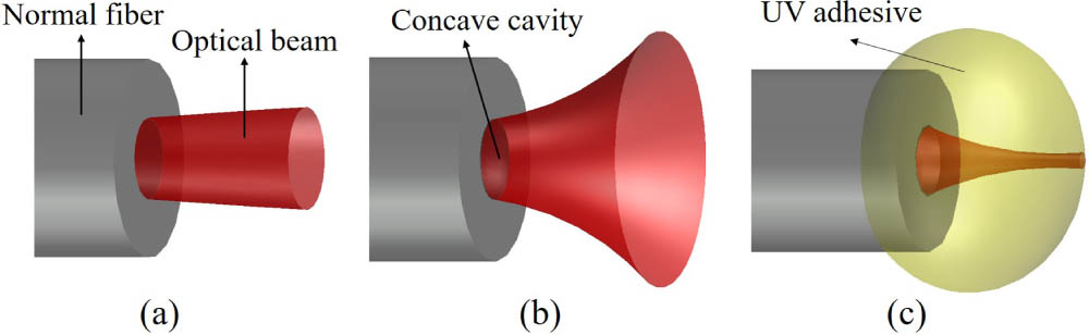
    Fig. 1. Schematic diagram of the output optical beam from (a) a normal fiber facet, (b) the fiber facet with concave cavity, and (c) the FECL with UV adhesive.
    Schematic of the FECL fabrication process.
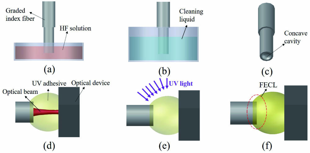
    Fig. 2. Schematic of the FECL fabrication process.
    Measured microscope images and sectional height profiles of the etched fiber facet: (a) NMF facet, (b) NMF height profile, (c) OM4 multimode fiber facet, (d) OM4 multimode fiber height profile.
    Fig. 3. Measured microscope images and sectional height profiles of the etched fiber facet: (a) NMF facet, (b) NMF height profile, (c) OM4 multimode fiber facet, (d) OM4 multimode fiber height profile.
    (a) Measured cavity depths of NMF under etching time varying from 8 to 30 min. (b) and (c) are height profiles with paraboloid fitting after 12 min and 28 min etching, respectively.
    Fig. 4. (a) Measured cavity depths of NMF under etching time varying from 8 to 30 min. (b) and (c) are height profiles with paraboloid fitting after 12 min and 28 min etching, respectively.
    Simulated optical beam field of the output fundamental mode: (a) NMF without etching, (b) facet cavity without filling the UV adhesive, and (c) FECL with UV adhesive.
    Fig. 5. Simulated optical beam field of the output fundamental mode: (a) NMF without etching, (b) facet cavity without filling the UV adhesive, and (c) FECL with UV adhesive.
    Simulated fundamental mode optical beams: (a) K=0.09, (b) K=0.11, (c) K=0.13, (d) K=0.15 with fixed NUV value at 1.6; (e) NUV=1.56, (f) NUV=1.6, (g) NUV=1.64, (h) NUV=1.68 with fixed K value at 0.12.
    Fig. 6. Simulated fundamental mode optical beams: (a) K=0.09, (b) K=0.11, (c) K=0.13, (d) K=0.15 with fixed NUV value at 1.6; (e) NUV=1.56, (f) NUV=1.6, (g) NUV=1.64, (h) NUV=1.68 with fixed K value at 0.12.
    Simulated reduction of the effective area of fundamental mode. The inset figures: (1) fundamental mode in the NMF; (2)–(5) shrunken mode fields of different FECLs.
    Fig. 7. Simulated reduction of the effective area of fundamental mode. The inset figures: (1) fundamental mode in the NMF; (2)–(5) shrunken mode fields of different FECLs.
    Simulated longitudinal displacement tolerance of fundamental mode spot effective area at different K.
    Fig. 8. Simulated longitudinal displacement tolerance of fundamental mode spot effective area at different K.
    Simulated LP11 mode optical field simulation: (a) K=0.09, (b) K=0.11, (c) K=0.13, (d) K=0.15, (e) NUV=1.56, (f) NUV=1.6, (g) NUV=1.64, and (h) NUV=1.68. The NUV value is fixed at 1.6 in (a)–(d) and the K value at 0.12 in (e)–(h), respectively.
    Fig. 9. Simulated LP11 mode optical field simulation: (a) K=0.09, (b) K=0.11, (c) K=0.13, (d) K=0.15, (e) NUV=1.56, (f) NUV=1.6, (g) NUV=1.64, and (h) NUV=1.68. The NUV value is fixed at 1.6 in (a)–(d) and the K value at 0.12 in (e)–(h), respectively.
    Simulated reduction of the effective area of the LP11 mode. The inset figures: (1) LP11 mode in the NMF; (2)–(5) shrunken mode fields after different FECLs.
    Fig. 10. Simulated reduction of the effective area of the LP11 mode. The inset figures: (1) LP11 mode in the NMF; (2)–(5) shrunken mode fields after different FECLs.
    Simulated longitudinal displacement tolerance of the LP11 mode spot effective area after different FECLs. Displacement from the minimum spot area from plus to minus 12 µm.
    Fig. 11. Simulated longitudinal displacement tolerance of the LP11 mode spot effective area after different FECLs. Displacement from the minimum spot area from plus to minus 12 µm.
    Schematic diagram of two kinds of inverse tapers: (a), (b) the top view and sectional view of the inverse taper and (c) top view of the Y-junction inverse taper waveguide.
    Fig. 12. Schematic diagram of two kinds of inverse tapers: (a), (b) the top view and sectional view of the inverse taper and (c) top view of the Y-junction inverse taper waveguide.
    Simulated coupling efficiency of the fundamental mode from the FECL to the inverse taper under different cavity coefficient K: (a) longitudinal coupling tolerance along with longitudinal displacement and (b) lateral coupling tolerance along with horizontal alignment.
    Fig. 13. Simulated coupling efficiency of the fundamental mode from the FECL to the inverse taper under different cavity coefficient K: (a) longitudinal coupling tolerance along with longitudinal displacement and (b) lateral coupling tolerance along with horizontal alignment.
    Simulated coupling efficiency of the LP11 mode coupling from the fiber to the Y-junction inverse taper with different K: (a) coupling tolerance at the optimal coupling point in the longitudinal direction and (b) lateral coupling tolerance of the coupling efficiency.
    Fig. 14. Simulated coupling efficiency of the LP11 mode coupling from the fiber to the Y-junction inverse taper with different K: (a) coupling tolerance at the optimal coupling point in the longitudinal direction and (b) lateral coupling tolerance of the coupling efficiency.
    Simulated transmission spectrum of the FECL coupling to inverse taper for (a) the fundamental mode and (b) the LP11 mode.
    Fig. 15. Simulated transmission spectrum of the FECL coupling to inverse taper for (a) the fundamental mode and (b) the LP11 mode.
    K0.090.100.110.120.130.14
    Optimal coupling distance (µm)34282317139
    80% longitudinal tolerance (µm)>40>40>30>302920
    80% lateral tolerance (µm)2.01.81.61.61.51.4
    Table 1. Simulated Optimal Coupling Distance, Longitudinal and Lateral 80% Coupling Tolerance of Fundamental Mode Coupling from Fiber to Inverse Taper
    K0.090.100.110.120.130.14
    WS (µm)4.14.03.73.63.43.4
    80% longitudinal tolerance (µm)>40>40>30>302920
    80% lateral tolerance (µm)2.01.81.61.61.51.4
    Table 2. Simulated Optimal WS Value, Longitudinal and Lateral Coupling Tolerance with 80% Efficiency, for LP11 Coupling from Fiber to Y-Junction Inverse Tapers
    Kanglin Li, Jiangbing Du, Weihong Shen, Jiacheng Liu, Zuyuan He. Improved optical coupling based on a concave cavity lens fabricated by optical fiber facet etching[J]. Chinese Optics Letters, 2021, 19(5): 050602
    Download Citation