Dmitrii Andreev, Artem Kuskov, Edl Schamiloglu. Review of the relativistic magnetron[J]. Matter and Radiation at Extremes, 2019, 4(6): 067201
Copy Citation Text
The cavity magnetron is the most compact, efficient source of high-power microwave (HPM) radiation. The imprint that the magnetron has had on the world is comparable to the invention of the nuclear bomb. High- and low-power magnetrons are used in many applications, such as radar systems, plasma generation for semiconductor processing, and—the most common—microwave ovens for personal and industrial use. Since the invention of the magnetron in 1921 by Hull, scientists and engineers have improved and optimized magnetron technology by altering the geometry, materials, and operating conditions, as well as by identifying applications. A major step in advancing magnetrons was the relativistic magnetron introduced by Bekefi and Orzechowski at MIT (USA, 1976), followed by the invention of the relativistic magnetron with diffraction output (MDO) by Kovalev and Fuks at the Institute of Applied Physics (Soviet Union, 1977). The performance of relativistic magnetrons did not advance significantly thereafter until researchers at the University of Michigan and University of New Mexico (UNM) independently introduced new priming techniques and new cathode topologies in the 2000s, and researchers in Japan identified a flaw in the original Soviet MDO design. Recently, the efficiency of the MDO has reached 92% with the introduction of a virtual cathode and magnetic mirror, proposed by Fuks and Schamiloglu at UNM (2018). This article presents a historical review of the progression of the magnetron from a device intended to operate as a high-voltage switch controlled by the magnetic field that Hull published in 1921, to the most compact and efficient HPM source in the twenty-first century.
I. INTRODUCTION
In his 1948 essay “Maggie” published in Astounding Science-Fiction, J. J. Coupling (pseudonym of J. R. Pierce) writes1
“The magnetron was announced quietly in a paper by A. W. Hull of the General Electric Company, published in the Physical Review in 1921—twenty six years ago. Don’t think, however, that mere stupidity kept us from having microwave radar on the spot! The magnetron of those days was a very simple device, and it did not have anything to do with radio at all. In fact, Hull thought of it as a means for turning high voltage d-c on and off.”
Later, he goes on to state
“This was then the magnetron in 1921. It was not a radio tube at all. It was a means for controlling currents at high voltages by means of a magnetic field. You cannot keep a good tube down, though, and it was not long before experimenters found out something about magnetrons in spite of themselves. When the magnetic field in magnetrons is high enough so that the electrons can just barely reach the anode, or even high enough so that electrons should not be able to quite reach the anode, the magnetron tends to oscillate and generate radio-frequency energy.”
This article reviews the relativistic magnetron from the moment that the magnetron idea was first published by Hull, through the early developments leading to the cavity magnetron, and then to the advances leading to the relativistic magnetron. The invention of the cavity magnetron in 1940 (through the Tizard Mission2) and the subsequent development of radar and industrial applications are considered a “major innovation” according to the definition often used by technology historians.3 Today, industrial cavity magnetrons abound and routinely operate reliably with beam-to-microwave conversion efficiencies exceeding 80%. The next big advance in the cavity magnetron was the relativistic magnetron, which was first investigated by Bekefi and Orzechowski at MIT in 1976.4 In that seminal work, the authors achieved 900 MW in the S-band with nearly 20% beam-to-microwave conversion efficiency by extracting the radiation radially from one of six cavities. The MIT work was followed by the invention of the relativistic magnetron with diffraction output (MDO) by Kovalev and Fuks at the Institute of Applied Physics (Soviet Union) in 1977.5 The MDO was not pursued further, because of its poor single-digit efficiency. The performance of relativistic magnetrons did not advance significantly until researchers at the University of Michigan (UM) and University of New Mexico (UNM) independently introduced new priming techniques and new cathode topologies in the 2000s,6–10 and researchers in Japan identified a flaw in the original MDO design from the Soviet Union.11 The Japanese group achieved 37% efficiency in simulations of an improved MDO, although subsequent experiments did not include power diagnostics to compare with the simulation results.12 The UNM researchers utilized the transparent cathode in a further refinement of the MDO and achieved 70% efficiency in simulations13 and 63% efficiency in experiments,14 limited by arcing of the cathode endcap. Recently, the efficiency of the MDO has attained the same level as the electronic efficiency and has reached 92% with the introduction of a virtual cathode and magnetic mirror, proposed first by Fuks and Schamiloglu at UNM.15
This article presents a historical review of the progression of the magnetron from an interesting idea by Hull published in 1921 to the most compact and efficient high-power microwave (HPM) source in the twenty-first century. (Note that the relativistic magnetron has been covered earlier in a number of articles and book chapters,16–19 but this is the first comprehensive review with historical context, and it is current as of the writing of the manuscript.) We will restrict this review to the relativistic cavity magnetron with anode vanes.
The remainder of the article is organized as follows. Section II reviews the early years of magnetron development around the world. Section III reviews the early development of the relativistic magnetron at MIT, the MDO at the Institute of Applied Physics, and induction linear accelerator-driven relativistic magnetrons at the Institute of Nuclear Physics, Tomsk Polytechnic Institute. Section IV reviews the work performed at Physics International, including phase-locking relativistic magnetrons. Section V reviews the more recent advances led by UM and UNM, as well as the most important recent achievements in China and Israel over the last decade. Section VI summarizes the progress made in relativistic magnetrons, along with obstacles that have been eliminated, and projects forward what new developments might emerge in the field.
II. EARLY MAGNETRON DEVELOPMENT
A. Hull’s magnetron
Ever since the work of Plücker and Hittorf in 1869,20 it has been well known that magnetic deflection can be used to control electron beams. In 1921, in an attempt to circumvent the triode patents of Lee de Forest, the American physicist Albert W. Hull introduced an early concept of a vacuum electric device controlled by a magnetic field.21 The term “magnetron” for such a device was coined at General Electric, Schenectady, NY and has been referred to as a “Greco/Schenectady” word (see https://www.armms.org/media/uploads/06_armms_nov12_rburman.pdf). The magnetron belongs to the kenotron family of devices. The word “kenotron” is derived from the Greek kenos (κενός), meaning “empty space” (vacuum), and tron, used in Greek to denote an instrument.22
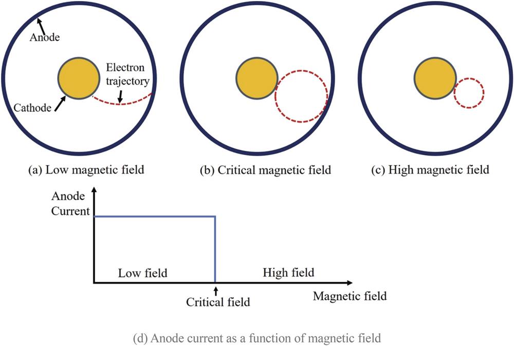
Electrically, the magnetron is a valve that uses a magnetic field to control the anode current, as shown in Fig. 1. When a constant voltage is applied between the cathode and the anode, the current starts flowing. If the magnetic field is low, the current is very weakly affected by it, as shown in Fig. 1(a). At a critical value of the magnetic field, the current completely stops, as shown in Fig. 1(b). When the magnetic field is at a critical value, the electrons move at a critical drift velocity, which allow their energy to be transferred to the energy of the electromagnetic waves and generate microwaves. At a higher magnetic field, the current ceases to reach the anode, as shown in Fig. 1(c). The dependence of anode current as a function of magnetic field is shown in Fig. 1(d).
Figure 1.Magnetron operation as a function of magnetic field: (a) low magnetic field; (b) critical magnetic field; (c) high magnetic field. (d) Anode current as a function of magnetic field.
The early magnetron was a vacuum tube with a tungsten filament for a cathode surrounded by a solid or meshed anode section, as shown in Fig. 2. The axial symmetry is critical for the azimuthal drift velocity of electrons in cylindrical geometry.21
Figure 2.CAD drawing of the original Hull magnetron.
The circuit that powered the Hull magnetron is depicted in Fig. 322 (the Hull circuit). The power source B1 provides current to heat up the tungsten filament, which starts the electron emission. The power source B2 imposes a constant voltage between the anode and the cathode, which creates a radial electric field. The power source B3 provides the energy for the solenoid S that produces the axial magnetic field in the magnetron tube.
Figure 3.The Hull magnetron circuit. The variables are described in the text. Reprinted with permission from Hull, J. Am. Inst. Electr. Eng. 40, 715–723 (1921). Copyright 1921 IET.
The perpendicular electric and magnetic fields produce an electron drift in the azimuthal direction. Such drifts are the so-called cross-field drifts, and for that reason magnetrons are called cross-field devices.
The technology for ultrashort waves was not in demand before the 1920s, but with advances in aviation, radio-wave-based detection became popular among most industrially advanced countries. Besides the USA, the Soviet Union, France, Germany, and the UK were seeking to develop sources for early radar systems.
B. Early work in the Soviet Union
The government of the Soviet Union was very interested in technological advances in radio technology and founded the Nizhny Novgorod Radio Laboratory (NRL) in 1918. In 1924, Professor Roganskiy and his student Slutskin from the Kharkiv Institute of Physics and Technology (KIPT) began their research, which led to the development of a magnetron that produced electromagnetic waves with a shortest wavelength of 7 cm.23 This was a two-segment split magnetron. After the initial experimental success, Slutskin became a scientific supervisor in KIPT and later published his findings on the first Soviet cavity magnetron in technical journals in the 1930s.23 The two-segment magnetron was later improved to a four-segment magnetron, shown in Fig. 4, which was a great success.23 This magnetron operated at a wavelength of 20 cm, with an output power of roughly 8–15 W.
Figure 4.Four-segment magnetron of Slutskin from Kharkiv, Soviet Union. Reprinted with permission from Borisova, in Proceedings of International Conference on the Origins and Evolution of the Cavity Magnetron, Bournemouth, UK, April 2010 (IEEE, 2010), pp. 23–33. Copyright 2010 IEEE.
Based on this work on two- and four-segment magnetrons, Alekseev and Malyarov, led by Bonch-Bruevich, began the development of the cavity magnetron. In August 1936, Alekseev and Malyarov first achieved promising results with a tungsten cathode and an anode block with four resonators made from tantalum sheet.24 The maximum power achieved was 10 W at 9 cm. However, overheating of the anode was a serious problem. In September 1936, a similar experiment was repeated, but with a copper anode cooled by flowing water. The results were published in March–April 1937, where the magnetron output was 300 W at 9 cm wavelength, which resulted in 20% efficiency. The same team led by Bonch-Bruevich developed four-cavity magnetrons for 1.0, 2.5, 5.0, 7.5, and 9.0 cm wavelengths at similar efficiencies.24
C. Early French work
The early 1920s in France were mostly focused on a radiotelegraphy or radiotelephony using “radio frequencies” with a very large wavelength, down to tens of meters. A small minority of scientists were interested in high-frequency waves beyond 1 GHz. In 1923, Professor Mesny at the Laboratoire National de Radioélectricité (LNR) with his colleague David developed resonant magnetrons for wavelengths down to about 1.2 m.25 The results were demonstrated by producing a radio link using “short” waves at the Physics and Wireless Telegraphy Exhibition in Paris.25
In early 1931, a very impressive result was demonstrated in the form of a two-way radio link established across the English Channel by an Anglo-French team. The power of the transmitted beam generated using a Barkhausen–Kurz oscillator was 0.5 W at 18 cm wavelength. The experiment attracted attention from scientists all over the world, but these developments were ultimately limited by the electron transit time between electrodes.25 A new system needed to be developed, which shifted the attention of researchers to magnetron technology.
During this time, the young physicist Ponte was recruited to the LNR and became curious of work by the Japanese researchers Okabe26 and Yagi,27 who formulated the first theoretical explanations for the oscillation modes. The Okabe theory distinguished two separate modes: “type A” oscillations appeared at a critical magnetic field, where the oscillation frequency was dependent on the geometry of the vacuum tube (observed by the Czech scientist Žaček28), and “type B” oscillations were associated with a “negative resistance effect” (predicted by the German physicist Habann29). The type B oscillator frequency could be tuned depending on the external resonant circuit.
Ponte chose the “negative resistance effect” type oscillation to build his first magnetron because the idea of frequency tunability seemed very practical. In 1932, Ponte had a working magnetron as shown in Fig. 5,25 with 40 W output power and wavelength 3 m, and later he went down to 80 cm wavelength at a similar power output.30,31 During his experiments, Ponte noticed that the efficiency of the type B magnetron decreased at shorter wavelengths, and he needed to reduce the anode size, which required new cooling techniques that made the system less practical. Additionally, the type A magnetron allowed the division of the anode into more than two segments to extend the upper frequency limit, as was shown by Okabe.26
Figure 5.The first Ponte decimeter magnetron (λ = 80 cm), 1932. Reprinted with permission from Blanchard, in Proceedings of International Conference on the Origins and Evolution of the Cavity Magnetron, Bournemouth, UK, April 2010 (IEEE, 2010), pp. 5–10. Copyright 2010 IEEE.
In 1932, Gutton joined Ponte’s team in the LTR. He directed his research into the type A magnetron. He first designed an eight-segment anode, which was named “M16,” and by 1937 was able to produce a reliable 10 W at wavelengths varying from 6 to 20 cm. The eight-segment magnetron, shown in Fig. 6,25 produced 10 W at a wavelength of 16 cm with about 15% efficiency. The magnetron voltage was 765 V and the magnetic field was 430 G.32
Figure 6.The Gutton magnetron (M16) with its permanent magnet. Reprinted with permission from Blanchard, in Proceedings of International Conference on the Origins and Evolution of the Cavity Magnetron, Bournemouth, UK, April 2010 (IEEE, 2010), pp. 5–10. Copyright 2010 IEEE.
Once the output powers started growing, new cathode technologies were tested, and in June 1939 an oxide-fitted M16 produced a peak power up to 300 W and later achieved 1 kW.
D. Early German work
The first “real” magnetron with a split anode was described by Habann in Germany in 1924. The construction was reminiscent of the Hull tube, except the anode was split into two parts where Habann first found a “negative impedance effect” that is now known as Habann oscillations.29
In common with almost all industrially advanced countries, Germany started the development of their Funkmesstechnik or radar in 1930, and this required the production of high-power and high-frequency microwave sources. The early Funkmesstechnik33 hardware was first developed by the Pintsch Co. in Germany, as well as by Philips in the Netherlands, which in 1934 was successfully producing magnetrons for commercial use, as shown in Fig. 7.20
Figure 7.The early Philips split anode magnetron. Reprinted with permission from Goerth, in Proceedings of International Conference on the Origins and Evolution of the Cavity Magnetron, Bournemouth, UK, April 2010 (IEEE, 2010), pp. 17–22. Copyright 2010 IEEE.
A group of physicists working at the University of Birmingham and led by Boot and Randall were attempting to improve the klystron to operate as a centimeter wave power oscillator in 1939.34 The initial results were successful, but on moving to high-power, sub-10-cm wavelengths, it was realized that the cross-sectional area was too small to impart sufficient power to the electron beam. Boot and Randall realized that the problem could be solved with a magnetron, once a few obstacles were overcome. They proceeded to (a) design a suitable type of resonator (the design needed to include the number and the shape of the resonators), (b) develop a method of construction that ensured high electrical and thermal conductivity, and (c) design a high-frequency output circuit related to a chosen resonator system. The shape of the resonator that was chosen was based on the Hanson and Rayleigh design: a three-dimensional extension wire loop or a short corresponding extension of a short-circuited quarter-wave line.34 A photograph of an early copy of this cavity magnetron is shown in Fig. 8.35
Figure 8.Photograph of an early copy of the cavity magnetron. Reprinted with permission from Brittain, Phys. Today 38, 60–67 (1985). Copyright 1985 AIP Publishing LLC.
To simplify the manufacturing process, an anode resonator system was constructed out of a single piece of cylindrical copper stock. The central cavity formed the anode–cathode (A-K) gap spacing, as shown in Fig. 8. The resonator cavities were grouped around the central cavity, the heat being dissipated by conduction along the webs or segments between neighboring resonators. The operating parameters of the Boot and Randall cavity magnetron were calculated based on the wavelength, and for the given geometry were calculated to be 16 kV and 1000 G. The first experimental test was carried out in early 1940, with the output being 400 W at 9.8 cm wavelength.
The first cathodes used in the first cavity magnetron were made from tungsten and were planned to be used for continuous operation. Later, an idea was borrowed from the French (Gutton and Berline), who were using oxide-coated cathodes, and this was implemented in late 1940. The efficiency of the cavity magnetron was greatly improved to 10%–20% and the output power was increased to 50 kW.34
In August 1941, Sayers, who until then was working at Birmingham on high-power klystrons, became interested in the nature of mutual cavity coupling in the magnetron in an effort to understand the favorable interaction between the electrons and the resonators for various modes. Aside from the π mode, Sayers also detected two additional modes that were distinct. To isolate modes from each other, he suggested that every other cavity be connected together with a piece of wire. This technique is now called “strapping” and is used to avoid mode competition by locking in the desired mode.34 (We will return to strapping when discussing relativistic magnetrons in Sec. V J.)
Magnetron research was heavily influenced by World War II in nearly all of the countries described above. Very similar ideas in all these efforts materialized into products that nearly all countries produced, and that was the end of the period of initial evolution of conventional magnetrons. By the end of the 1950s, conventional magnetrons were improved to produce several kilowatts of power efficiently in the decimeter wave range, but the results were asymptotically approaching the power limit for such magnetrons. The main issue seemed to be cathode current production by the thermionic and secondary emission, which could produce several hundred amperes at best. Improvements in cathodes, materials, and designs led to conventional magnetrons reaching output powers of the order of 10 MW.36
New technology needed to be developed to increase the cathode current and the output power significantly beyond 10 MW. The advent of modern pulsed power37 provided this capability, and this led to the development of relativistic magnetrons and other HPM sources.
III. RELATIVISTIC MAGNETRON: EARLY WORK
Figure 9 presents an overview of the evolution of relativistic magnetrons (inspired by Fig. 10.1 in Ref. 16 and updated). Note that the vertical axis (years) is not on a linear scale.
Figure 9.Historical evolution of the relativistic magnetron (inspired by Fig. 10.1 in Ref. 16 and updated).
The first device where the growth of oscillations was powered using a pulsed power-driven relativistic electron beam was introduced by Bekefi and Orzechowski at MIT in 1976.4 It utilized explosive electron emission from a cylindrical graphite cathode at the center of a six-cavity magnetron. A schematic of this A6 magnetron is shown in Fig. 10.38 The characteristics of the magneton geometry are described by the following parameters: vane radius rv, anode radius ra, cathode radius rc, resonator cavity angle ψ, number of vanes N, and axial length of the anode blocks L.
Figure 10.Schematic of the first A6 magnetron at MIT. Reprinted from Palevsky and Bekefi, Phys. Fluids 22, 986–996 (1979). Copyright 1979 AIP Publishing LLC.
For explosive electron emission to be initiated, a threshold electric field needs to be applied between the cathode and the anode; for a smooth graphite cathode, the electric field needs to exceed about 100 kV/cm. Once electrons are emitted, they are subjected to the crossed axial magnetic field and the radial pulsed power electric field, which starts the azimuthal rotation of the Brillouin space charge cloud. The critical magnetic field to insulate the electron flow is given by the “Hull criterion”21whereThe constants m0 and e are the rest mass and charge of the electron, respectively, c is the speed of light in vacuum, and V is the potential applied across the radial A-K gap. Unlike in smooth-bore magnetrons, where the electromagnetic modes can be decomposed into rotating waves with phase velocities exceeding the speed of light, cavity magnetrons create a longer path for the rotating waves, slowing down their phase velocities to become synchronous with the group velocity of the electron cloud. The cavities are called “slow wave structures” and are used to establish synchronism between any of the modes in the cavity and the electron space charge. The strong wave–particle interaction results in an efficient conversion of beam energy to electromagnetic energy.
The axial magnetic field in a cavity magnetron is not constrained just by the Hull criterion. The operating mode is determined by the Buneman–Hartree condition,39 which also depends on the magnetic field,where ωn is the oscillation frequency of a given azimuthal mode of number n (n = 1, 2, 3, …), BBH corresponds to the critical magnetic field, and VBH corresponds to the applied voltage. The Buneman–Hartree condition provides a useful guide for controlling the operating mode in a relativistic magnetron.
The operating modes in a magnetron are mainly defined by the geometry of the magnetron and interaction space. There are an infinite number of resonances that exist in the structure, but we are only interested in those of lowest order to avoid mode competition. Probably the most famous canonical relativistic magnetron is the A6 magnetron that was developed by Bekefi.4,38,40 The geometric parameters for the A6 magnetron are ra = 2.11 cm, rv = 4.11 cm, rc = 1.58 cm, L = 7.2 cm, and ψ = 20°. The dispersion diagram for the A6 magnetron is shown in Fig. 11.38
Figure 11.Dispersion diagram of Bekefi’s A6 magnetron. Reprinted from Palevsky and Bekefi, Phys. Fluids 22, 986–996 (1979). Copyright 1979 AIP Publishing LLC.
The system is shown to be highly dispersive because, as the phase angle increases, the phase velocity decreases. The most convenient mode to operate in is called the π mode because the electric field in each neighboring vane is offset by exactly 180°, as shown in Fig. 12.38
Figure 12.Electric field distribution in an A6 magnetron for π and 2π (or 0) modes. Reprinted from Palevsky and Bekefi, Phys. Fluids 22, 986–996 (1979). Copyright 1979 AIP Publishing LLC.
Alternatively, when the electric field in every resonant cavity is in phase, the mode is called the 2π or 0 mode. The π and 2π modes are the most popular modes for magnetron operation; however, other modes exist, such as the 2π/3 and 4π/3 modes, but they are not as efficient.
The typical parameters for the A6 magnetron utilize a voltage of 300–800 kV and an axial magnetic field of 4.0–8.0 kG.4,38,40 In Ref. 4, Bekefi and Orzechowski demonstrated a magnetron operating at 3 GHz frequency with output power of 1.7 GW that was powered with a 360 kV voltage and 7.5 kG magnetic field. The experiment was successful and showed 35% efficiency, starting a new era of relativistic magnetrons.4,38,40Table I compares and contrasts the conventional and relativistic magnetrons.16
Parameter
Conventional magnetron
Relativistic magnetron
Voltage
≤100 kV
≥500 kV
Current
∼100 A
≥5–40 kA
Cathode
Thermionic and secondary emission
Explosive emission
Pulse duration
∼1 ms
∼100 ns
Risetime
≤200 kV/ms
∼100 kV/ns
Power
≤10 MW
∼1 GW
Tunable range
∼5%
∼30%
Efficiency
∼50%
∼20%–40%
Table 1. Comparison of operational parameters of typical non-relativistic and relativistic magnetrons.16
Many different groups in the USA and the Soviet Union adopted the A6 magnetron design. Ballard et al.41 were the first to study the A6 relativistic magnetron (or any relativistic magnetron for that matter) using a thermionic cathode. The A6 magnetron is the most widely discussed relativistic magnetron in the literature (see Refs. 4, 16, 18, 19, 38, and 40–43, and references cited therein).
B. Work in the Soviet Union following Bekefi
1. Fuks and the relativistic magnetron with diffraction output (MDO)
Following Bekefi’s success4,16,18,19,38,40–43 researchers in the Soviet Union started to explore relativistic magnetrons with axial extraction, with wavelengths at the shorter end of the centimeter range.5 Instead of extraction of the microwave power through a radial slot from one of the cavities, they proposed a smooth continuous transition from the interaction region by tapering the anode vanes to the output waveguide. They called this the diffraction method and built the first eight-cavity X-band magnetron with diffraction output (MDO) (Fig. 13).
Figure 13.Photograph showing the diffraction output of an eight-cavity X-band MDO. Courtesy of Fuks, University of New Mexico (retired), Albuquerque, NM.
The experiment was conducted with a 600 kV pulsed power supply, and 500 MW output power was achieved with low electron-to-microwave conversion efficiency. They observed anode erosion, significant power drop after 500 pulses, and the pulse shortening effect, which they explained by “the short-circuiting of the interelectrode gap by the anode plasma which is produced when the anode sheets are heated by the anode current.”
The operating current of the magnetrons at that time were below the currents that pulsed power systems could provide. Increase in volume would normally increase the mode competition, but, by using the diffraction output coupling, it became possible to increase the length of the interaction region without disrupting single-mode operation. Increase in the anode current near cutoff resulted in better conditions for trapping of electrons by the RF field, which helped to reach 4 GW output power at 0.95 MW applied voltage.
However, work on the MDO was abandoned owing to the poor efficiency of the device. We will revisit this later.
2. Work at the Institute of Nuclear Physics at Tomsk Polytechnic Institute
Researchers at the Institute of Nuclear Physics at Tomsk Polytechnic Institute led by Didenko studied long-pulse magnetrons driven by linear induction accelerators (LIAs).44,45 They demonstrated the generation of 1 µs long microwave pulses, which they extracted radially from the magnetron. They also demonstrated the generation of trains of pulses with very good shot-to-shot stability.
IV. ADVANCES MADE AT PHYSICS INTERNATIONAL: PHASE LOCKING, FREQUENCY AGILITY, AND ORION
In 1985, Benford et al. developed a 6.9 GW, 4.5 GHz relativistic magnetron. In the late 1980s, and early 1990s, they studied phase locking and high-repetition-rate operation. They also developed the ORION HPM test source for the UK in the early 1990s. These advances at Physics International are reviewed below.
A. Phase locking
Power radiated by an HPM source has become an important benchmark over the decades. Since the invention of the cavity magnetron, various techniques and designs have been implemented to increase the output power, efficiency, and compactness of magnetrons. Based on the previous successes in achieving 1–10 GW output powers, new demands in high power (>100 GW), gigahertz-range antenna arrays have been expressed for strategic missile defense systems.46 To achieve this magnitude of radiated powers, two paths can be pursued: increasing the power of an individual source or combining multiple sources in a phase coherent array.47,48
The first approach is limited by gap closure, by electric field breakdown inside the cavities, at the dielectric output window, or in air due to the high-power densities, and by the size of the cavities. In large-volume cavities, mode competition can occur because the number of modes scales as V/λ3, where λ is the wavelength.47 The amount of radiated energy can be increased by increasing duration of the pulse; however, pulse shortening occurs in high-power systems. Therefore, the second approach is desirable. Phase locking produces an N-fold increase in radiated energy, which eliminates the need in increasing the pulse durations for an individual source, and an N2-fold increase in power flux density due to constructive interference. Therefore, combining power flux densities of phase-coherent sources eliminates the problem of breakdown in front of the radiating antenna. Magnetrons are widely used in phase-locked arrays owing to their high efficiency, compactness, and mode stability. There are ongoing studies on coherent phase combination of superradiant backward wave oscillators, which require only 25° phase coherence (see Ref. 49 and references cited therein).
For phase locking, the critical criterion is that the relative phases must be constant during each pulse and reproducible from pulse to pulse.47,48 This requirement of reproducibility distinguishes phase locking from frequency locking. Having an identical frequency of oscillation does not guarantee phase locking, because phase synchronism may not be achieved. Phase locking requires not only a constant phase difference between oscillators, but also an identical frequency, so phase-locked oscillators will always have the same frequency. This also means that a frequency-locked array may not be phase-locked.
There are two techniques allowing the phase locking of several magnetrons in an array: peer-to-peer (P2P) or master-to-slave (M2S) with weak or strong coupling. The differences between the P2P and M2S schemes are that the P2P output ports are loaded by a common or each one’s own external load, adjusting to each other during the operation. M2S uses an externally driven master oscillator whose outputs are connected to the inputs of slave oscillators.50 The second distinction reflects the ratio of the signal injected into a source for phase locking to the signal naturally occurring in that source. Operating in a weak-coupling regime would allow a low-power master oscillator to drive higher-power slave oscillators. For example, a conventional magnetron can drive a relativistic high-power magnetron. However, the drawback is that it takes a longer time to phase-lock an array. This is a disadvantage for high-power, short-pulse relativistic magnetrons; therefore, the strong-coupling regime is preferred. Strong coupling also allows magnetrons with large phase differences to be locked into an array.
Phase-locked arrays have been successfully tested in different regimes with different interconnection topologies.47,48 It was experimentally verified that a topology with maximum connectivity is the most desirable. Phase locking of an array of seven relativistic magnetrons, producing 2.9 GW at 2.8 GHz, was reported, as was burst-mode operation of 400–600 MW, 75 ns relativistic magnetrons in the frequency range of 1–3 GHz at up to 100 Hz for 10 s.
B. Frequency-agile relativistic magnetron
Levine et al.51 reported on the development of tunable magnetrons. Vanes were arranged in five closely spaced pairs in a rising-sun geometry, as shown in Fig. 14.19 Tuning was achieved by moving a sliding short in the cavity between the vane pairs, varying the depth of that cavity. That depth variation changed the frequency of the device, requiring a corresponding change of the magnetic field to maintain resonance. The moving tuning shorts were driven by piston rods from electric motors on the outside of the anode block. The tuning range for the L-band magnetron was approximately 24% about a center frequency of 1.21 GHz with 400 MW output power, while that for the S-band magnetron was 33% about a center frequency of 2.82 GHz with 500 MW output power. These types of relativistic magnetrons were used in the ORION HPM system to be described in Subsection IV C.
Figure 14.Tunable rising-sun relativistic magnetron at Physics International. This relativistic magnetron uses plungers moving back walls of three vanes for mechanical tunability. Extraction is through two waveguide ports, one of which is visible. Reprinted with permission from Benford, in Proceedings of International Conference on the Origins and Evolution of the Cavity Magnetron, Bournemouth, UK, April 2010 (IEEE, 2010), pp. 40–45. Copyright 2010 IEEE.
ORION is a state-of-the-art transportable, self-contained HPM test facility first fielded in 1995 in the UK52 and currently in operation at the Naval Surface Warfare Center, Dahlgren Division (Fig. 15). ORION was built for $7.5M (1995 dollars). The system is housed and transported in five ISO containers, has complete fiber-optic-linked computer controls and data acquisition, and carries its own prime power. At the heart of the system is a suite of four tunable magnetrons, each capable of delivering 400–800 MW. The frequency tuning is continuous, with no gaps in performance over the range from 1.07 to 3.3 GHz. ORION fires 1000 pulses in a burst at repetition rates up to 100 Hz. The thyratron-based modulator that drives the magnetrons has a pulsed power output that can be increased in discrete 50 ns steps up to a maximum duration of 500 ns. The microwaves are radiated from a high-efficiency, offset, shaped, parabolic antenna that illuminates a 7 m × 15 m, 3 dB beam spot at a 100 m range.
Figure 15.ORION outdoor testing facility when it was operational in the UK. Courtesy of Smith, L-3 Communications (retired), San Leandro, CA.
The ORION pulsed power system is a two-stage, oil-insulated, thyratron-switched modulator that pulse charges an 11-section ladder-type pulse-forming network through a step-up transformer and triggered gas output switch.52 Its main performance features are variable pulse duration, from 100 to 500 ns, variable voltage, from 200 to 500 kV, and pulse repetition rate up to 100 Hz. Its output impedance is 50 Ω, its rise time is < 30 ns, and its flatness is ±8%. Pulse duration is varied by manually removing inductors in 50 ns increments.
After the magnetron, a combiner/attenuator network provides continuous power variation over five orders of magnitude. The waveguide combiner/attenuator consists of a hybrid tee/phase shifter and power combiner to sum output from two magnetron arms, followed by a hybrid tee/phase-shifter attenuator to vary the radiated power over five orders of magnitude. There is a separate waveguide circuit for the three waveguide bands: WR770 (L-band, lower portion), WR510 (L-band, upper portion), and WR340 (D-band). The system is controlled with programmable stepper motors.
The ORION antenna system, which can be seen in Fig. 15, includes two offset, shaped, parabolic reflectors each with two pyramidal feed horns designed to maximize efficiency, reduce sidelobe level, and produce a 7 m × 15 m elliptical beam spot at a 100 m range. The antenna gain is 468 (26.7 dB). Modest pointing adjustments of about ±10° are possible with flexible waveguide sections and shims.
V. RECENT ADVANCES IN THE RELATIVISTIC MAGNETRON
A. New cathode topologies and magnetic priming
New cathode topologies led to advances in the performance of relativistic magnetrons discovered at UM,8,9,53 UNM,10,54 and the Air Force Research Laboratory.55 The main motivation was to provide a fast start of oscillation without the expensive microwave priming (RF priming) technique and eliminate mode competition. Researchers at UM also studied magnetic priming in relativistic magnetrons.7,56,57
The first paper on magnetic priming in conventional magnetrons was published by UM in 2003.6 It proposed the method of “hastening” the startup of a magnetron by introducing an azimuthally varying axial magnetic field of N/2 periodicity, where N is the number of cavities. It was tested experimentally (see Ref. 57 and references cited therein) on a 10-cavity oven magnetron, and the researchers discovered that the “close-in noise and the sideband noise have been completely eliminated, with little sacrifice in the efficiency and output power.” The theory was extended to relativistic magnetrons, where the N/2 azimuthal variations in the axial magnetic field led to “prebunching of the electrons” into a N/2-fold symmetry and “favored the excitation of the π mode, long before this internal electromagnetic mode appears.” To verify the feasibility of such an approach, studies were carried on the Bekefi A6 magnetron using the 2D MAGIC particle-in-cell (PIC) code.58 Compared with an unperturbed magnetic field, more rapid electron spoke formation was observed with magnetic priming.
However, magnetic priming requires external hardware, such as permanent magnets, to prebunch the electrons into spokes and excite a desired mode. Researchers at UM then proposed to prime a magnetron internally with a “cathode priming” technique.8,9,53 Threefold symmetry of the electron bunches was provided by ablating three azimuthally periodic emission regions on the cathode by projection ablation lithography (PAL) using a KrF laser. MAGIC 3D simulations were performed to demonstrate the suppression of the undesired 2π/3 mode during the startup and rapid phase locking into the π mode. It took half the time for the magnetron to start oscillating in the π mode compared with a solid cathode. It was noted that the reduction in startup time was about 50% for both magnetic priming and cathode priming, which led to future discoveries.
The next cathode topology was introduced independently by researchers at UM and UNM. UM proposed a three-cathode emitter technology for cathode priming,9 and UNM proposed a six-emitter “transparent cathode.”10 Once again, these approaches produced a threefold symmetry in the electron cloud to favor the π mode. The UNM researchers noted that both the cold and the hot frequencies were shifting depending on the cathode angular width and clocking, which offered the possibility of magnetron tuning by simply rotating the cathode inside the anode block.54 Compared with cathode and magnetic priming techniques, magnetron priming by the transparent cathode provided higher output power and efficiencies, as well as benefits such as rapid π mode growth and locking, as shown in Fig. 16.10
Figure 16.MAGIC 3D simulations performed at UNM showing the benefits of a transparent cathode in an A6 relativistic magnetron compared with a solid cathode or projection ablation lithography (PAL) cathode priming. Reprinted with permission from Fuks and Schamiloglu, Phys. Rev. Lett. 96, 205101 (2005). Copyright 2005 American Physical Society.
Researchers at UNM realized that the azimuthal component of the electric field is responsible for sweeping electrons into spokes and affecting the growth time of oscillations, and, on that basis, they proposed to remove longitudinal strips from a hollow, thin-walled cathode so that the azimuthal electric field penetrated to the axis. The field acting on the electron flow was then much stronger, and fast electron spoke formation was demonstrated in MAGIC using the cathode with six discrete emitting strips. The choice of number of emitters was based on the desire to promote rapid excitation of the 2π mode. The application of the transparent cathode imposes a strong azimuthal electric field on the electron flow around the cathode and a rapid start of oscillations. It was later realized that the transparent cathode provides cathode priming, magnetic priming (through the axial current from each emitter), and electrostatic priming.
The benefits of the transparent cathode were validated in experiments at UNM using the short-pulse SINUS-6-driven A6 magnetron.58Figure 17 is a photograph of the experimental setup.
Figure 17.Photograph of the SINUS-6 accelerator at UNM with the A6 magnetron with radial extraction.
A serious challenge to the HPM community in the 1990s was the emergence of “pulse shortening,” which was also a problem for the relativistic magnetron.60–64 Pulse shortening occurs when HPM generation ceases even though electron beam propagation continues. Unwanted excess plasma is considered the culprit in pulse shortening. For the case of pulse shortening in relativistic magnetrons, diode gap closure leading to impedance collapse is the cause.64
In the 2000s, Shiffler and colleagues at the Air Force Research Laboratory (Kirtland Air Force Base, NM) undertook a series of investigations into cold cathodes for HPM sources. They studied carbon velvet and carbon fiber cathodes with and without CsI coatings. They also studied the effects of brazing such cathodes in a hydrogen furnace (see Refs. 65 and 66 and references cited therein). They found that CsI coatings minimized cathode plasma formation on carbon velvet cathodes.65 The ORION HPM facility described in Sec. IV B was designed with a modular pulse-forming network such that the output voltage pulse was adjustable in 50 ns increments. The relativistic magnetron on ORION had never been operated using the fully available pulse length because of pulse shortening. Shiffler and colleagues performed a series of experiments where they used a CsI-coated carbon velvet cathode, and for the very first time ORION was operated using the full voltage pulse, and pulse shortening was found not to be an issue, as shown in Fig. 18.65
Figure 18.ORION relativistic magnetron performance with a CsI-coated carbon velvet cathode. The magnetron total current is shown in (a) for three different applied pulse durations, whereas the instantaneous RF electric field measured in an output waveguide is shown in (b). Note that the time scales on the two traces are different. Reprinted with permission from Shiffler et al., IEEE Trans. Plasma Sci. 36, 718–728 (2008). Copyright 2008 IEEE.
The UNM group also proposes that its MDO with a virtual cathode and magnetic mirror15 can eliminate pulse shortening, since there is no longer a physical cathode in the interaction region for diode impedance collapse to occur. This will be discussed further in Sec. V I.
C. The MDO revisited in Japan
In 2007, Daimon and Jiang from the Nagaoka University of Technology published an article11 where they revisited the X-band MDO5 from the Soviet Union using the MAGIC PIC code. To their surprise, they realized that the researchers in the Soviet Union5 had made an error and the extraction portion of the MDO was too small and the microwaves were evanescent at the output of the MDO instead of radiating. Daimon and Jiang corrected this in PIC simulations and increased the efficiency of the MDO from single-digit to 37%.
MAGIC was further used to compare the original MDO design with deepened vane structure geometries. First, cold simulations were performed to compare microwave propagation and mode conversion. No difference was observed inside the resonating cavity; however, the frequency spectrum observed in the waveguide was very distinct. Daimon and Jiang concluded that the modified configuration of the tapered mode converter is more effective than the original configuration in mode conversion for the fundamental frequency. Concomitant hot test simulations were performed, and it was shown that the output mode of the original configuration could not be identified, and the dominant frequency changed from 2.6 GHz inside the resonating cavity to 4.51 GHz at the output waveguide.11 Daimon and Jiang proved that in the original MDO configuration, the fundamental mode was reflected to the magnetron cavity and an evanescent mode was observed at the output. In the meantime, their modified configuration showed efficient mode conversion from the fundamental π mode at 2.6 GHz inside the magnetron cavity to the TE31 mode with the same frequency at the output waveguide.
It was demonstrated numerically that the output microwave power and efficiency are deeply affected by the configuration of the tapered mode converter. Numerical cold tests demonstrated improved microwave propagation from the magnetron cavity to the output waveguide. Hot test simulations demonstrated significant improvement of output power from 130 MW for the original MDO geometry to 1050 MW for the modified one, with an increase in the microwave-to-beam conversion efficiency from 3% to 37%. It was an important step to realize that the performance of a mode converter has a strong effect on magnetron performance.
Experimental verification was carried out on the ETIGO-IV LIA pulsed power generator, which was capable of generating 400 kV with 13 kA of current during a 120 ns pulse with 1 Hz repetition rate. An endcap was attached to the cathode axially downstream to suppress leakage current. A clear difference between the original MDO and the modified microwave outputs at the same diode voltage profile was detected. Significant improvement of the microwave output for the modified geometry was verified. However, the absolute radiated power output and conversion efficiencies were not obtained, owing to uncalibrated diagnostics.12
D. UNM revisits the MDO with transparent cathode
In 2002, Fuks and Schamiloglu67 revisited the MDO to optimize its performance. The UNM group also studied mode conversion from the MDO.68 The 2007 achievement by Daimon and Jiang stimulated further optimization of the MDO at UNM. Fuks and Schamiloglu further optimized the modified diffraction output and used their transparent cathode10,54 to achieve 70% efficiency in MAGIC simulations.13 The transparent cathode, consisting of separate longitudinal emitters periodically placed about radius Rc, had demonstrated faster start-of-oscillations, higher output power, and greater electronic efficiency compared with a solid cathode in either the relativistic magnetron with radial extraction or the MDO. The geometry of the cavities and antenna were optimized to find the maximum radiation power and electronic efficiency, to decrease the MDO volume, and thus to reduce the power supply required for the magnetic field-producing system. These adjustments were optimized around the operational parameters achievable experimentally using the modified PI-110 accelerator at UNM (Fig. 19).14
Figure 19.Photograph of the modified PI-110A accelerator (back) adjacent to the SINUS-6 (front) at UNM.
Subsequent experiments at UNM demonstrated 63% efficiency for the MDO with transparent cathode using an endcap to suppress axial leakage current.14 When electrical breakdown of the endcap occurred, the efficiency fell to 35%.
E. Chinese work on the relativistic magnetron and MDO
Following the MDO design optimization work of Fuks and Schamiloglu,67 Li and colleagues at the National University of Defense Technology, Changsha, launched an active program in optimizing the MDO.69–82 Additional groups in China working on the relativistic magnetron and the MDO include the School of Physical Electronics, University of Electronic Science and Technology of China, Chengdu; the Institute of Applied Physics and Computational Mathematics, Beijing; the Laboratory of High Power Microwave Technology, Institute of Applied Electronics, China Academy of Engineering Physics, Mianyang; and the Key Laboratory of Physical Electronics and Devices of the Ministry of Education, Xi’an Jiaotong University, Xi’an.83–96
The main contributions from the Chinese groups have been as follows:
optimization of the magnet field distribution in the output of the MDO to improve efficiency;
demonstration of frequency agility through the use of dielectric inserts;
experiments to validate their PIC models;
studies of output mode conversion and polarization;
development of an A6 magnetron with permanent magnet (to be elaborated on in Sec. V H);
development of an MDO with stepped cavities;
studies of the influence of secondary electron emission on relativistic magnetron operation through PIC simulations;
studies of different cavity designs for relativistic magnetrons, such as the rising sun and “crab-like” variants, through PIC simulations.
F. Israeli work on the relativistic magnetron
The group led by Krasik at the Technion Israel Institute of Technology in Haifa, Israel has been researching relativistic magnetrons since 2008.97–109 In their experiments, they utilize a LIA, similar to the experiments at the Institute of Nuclear Physics in Tomsk, Russia and Physics International in the USA. Their experiments are notable in that a wide area of spectroscopic diagnostics have been employed to study plasma evolution during the course of relativistic magnetron operation.
The main contributions from the Israeli group have been as follows:
studies of the evolution of plasma during S-band magnetron operation and its effects on mode stability;
the use of an active plasma cathode in an S-band magnetron;
studies of the effects of secondary electrons on the cathode in a magnetron;
radial extraction of energy from multiple cavities;
studies of pulse shortening in relativistic magnetrons and the role of anode block axial endcaps and power flow;
development of novel approaches for implementing a permanent magnet on a relativistic magnetron (to be elaborated on in Sec. V H).
G. RF priming in relativistic magnetrons and RF mode switching in the MDO
The group at UM proposed to use RF priming to provide rapid startup, increased pulse width, and mode locking of relativistic magnetrons.110 The RF priming source was a 100 kW pulsed magnetron operating at 1.27–1.32 GHz. Tuning stubs were utilized in a Titan six-cavity structure to adjust the frequency of the relativistic magnetron to match that of the priming source. Experiments were performed on rising sun as well as standard anode configurations. The results showed significant reductions in microwave output delay and mode competition, even when Adler’s relation was not satisfied.111
The UNM group proposed RF mode switching in an MDO.112–114 For an MDO, there is a critical magnetic field that separates the operation of the device in two different modes, as shown in Fig. 20.112 If one were to operate near this critical magnetic field and injected on the order of 100 kW of the frequency of the adjacent mode, then the MDO would operate in this new mode. This effect can be explained as shown in Fig. 21.112
Figure 20.Output power P and efficiency η as functions of magnetic field for an MDO. The critical magnetic field is H00 = 4.527 kOe. Reprinted with permission from Liu et al., Appl. Phys. Lett. 97, 251501 (2010). Copyright 2010 AIP Publishing LLC.
Figure 21.(a) The van der Pol diagram115 of a system with a saddle point F0 between stable states F1 and F2. (b) Ball on top of a hill between two valleys. This mechanical system is an analog for RF mode switching in an MDO. Reprinted with permission from Liu et al., Appl. Phys. Lett. 97, 251501 (2010). Copyright 2010 AIP Publishing LLC.
H. Relativistic magnetron and compact MDO with permanent magnet
The use of electromagnets in pulsed power-driven HPM systems has many disadvantages. They are not compatible with magnetron operation in repetitive mode because of the long time required for capacitors to recharge before being able to be discharged again. They require very large capacitor banks and complicated triggering circuits, which are heavy and hard to maintain. Finally, electromagnets decrease the overall system efficiency where they are used.
The first study of the use of permanent magnets in an A6 magnetron was performed at UESTC in Chengdu, China.88 The configuration utilized a triangular distribution of pole pieces external to the magnetron. A power of 540 MW at 2.65 GHz was demonstrated with a magnetic field of about 5.9 kG. NdFeB ring magnets were used along with pole pieces and a magnetic yoke. The efficiency was single-digit. Weight information on the magnetic system was not provided.88
The next group to design a permanent magnet solution was the UNM group, which developed a compact MDO and designed a permanent magnet around it.116–119 NdFeB (grade N40M) magnets were chosen for this work as well owing to their high coercivity (the resistance of a magnetic material to changes in magnetization), relatively low price, and adaptable geometry. The required geometry can be achieved by stacking different magnet modules together to obtain the desired shape with corresponding magnetic field strength on the axis of the magnet. (In another application, neodymium magnets were used at UNM as part of a cathode endcap to further reduce downstream leakage currents.120)
The dimensions of the permanent magnet for the UNM compact A6 MDO were finalized117 using the Finite Element Method Magnetics magnetic simulation software and MAGIC. Electron Energy Corporation (https://www.electronenergy.com) was the vendor selected to manufacture the permanent magnet for this application. It was verified not only that electron trajectories behave as expected, but also that the upstream and downstream leakage currents were significantly reduced with the permanent magnet design. The permanent magnet provided 0.33 T in the bore. The weight of the entire magnet assembly was 50 kg.
A compact A6 relativistic magnetron with diffraction output using a transparent cathode, simple mode converter, and a permanent magnet were simulated and experimentally tested at UNM on the PI-110A accelerator. The standard compact MDO with a simple mode converter and transparent cathode radiates a TE11 mode axially through a cylindrical horn antenna. Figure 22 shows a photograph of the UNM compact A6 MDO and permanent magnet.
Figure 22.Photographs of the UNM compact A6 MDO (a) and the permanent magnet (b). The photograph in (a) shows how the compact MDO radiates a TE11 mode from the generated mode. As is evident, two of the six cavities are closed off and four are opened. The electric fields from the two top open cavities and two bottom open cavities sum to radiate a linearly polarized TE11 mode without requiring the bulk mode converter of the full MDO.
Results from UNM experiment reproduced the qualitative behavior of the simulations, and the simulated operating frequency of 2.5 GHz was measured experimentally. The anticipated Gaussian radiation pattern from the radiated TE11 mode was also experimentally verified in two ways, first by a neon bulb grid array and second by measuring the peak of the radiated microwave pulse relative to varying locations.
The third group to design and implement a permanent magnet solution for a relativistic magnetron is from the National University of Defense Technology in Changsha, China. Their device is shown in Fig. 23.121 Their source was 330 mm long, with a total weight of 50 kg, including 25 kg for the magnets providing 0.3 T in the bore. The operating frequency ranged from 2.08 GHz to 2.78 GHz within a 3 dB power loss. The tuning bandwidth was 29%. The device generated about 1 GW with 24% efficiency, with average FWHM pulse length greater than 50 ns.
Figure 23.Photograph of the NUDT permanent magnet relativistic magnetron.121
Finally, the group from the Technion in Israel utilized N52 magnets in a clever approach, inserting them into the anode block of a six-cavity magnetron and within the cathode to generate a magnetic field of about 0.3 T in the magnetron, as shown in Fig. 24.109 When driven by a 250 kV, 2 kA pulse, their device generated several tens of megawatts of power in S-band.109
Figure 24.(a) External view of anode with the angular segment (AS) NdFeB permanent magnets and the anode endcap seen separately. (b) Same as (a), but with the cathode and the anode endcap installed. (c) Long cathode without inserted rod magnets. (d) Short cathode with rod magnets inserted. (e) Same as (c), but with rod magnets inserted. Reprinted with permission from Krasik et al., IEEE Trans. Plasma Sci. 47, 3997–4005 (2019). Copyright 2019 IEEE.
I. UNM MDO with virtual cathode and magnetic mirror
At UNM, the traditional solid cathode was replaced with a transparent cathode for more rapid start of oscillations, higher efficiency, and mode stability when combined with a proper magnetic field.10 Experimentally, these results were verified with the A6 magnetron with radial microwave extraction.59 In MAGIC PIC simulations, we found that a transparent cathode can improve the electron-to-microwave conversion efficiency for the MDO from 37% to 70%.13 It was later demonstrated experimentally that an efficiency of 63% was achieved in experiments until endcap failure occurred.14
At UNM, the trend has been to remove cathode material (moving from a solid cathode to a transparent cathode). Recently, UNM proposed to remove the cathode entirely from the interaction region of the MDO.122–125 An electron beam is injected external to the MDO interaction region, and the dimensions are selected such that a virtual cathode is formed in the MDO. It was shown that for the S-band MDO with interaction length of 7.5 cm, the time of virtual cathode formation is very short compared with the voltage rise time. The virtual cathode is formed in a diode with magnetic insulation by the time the applied voltage would normally reach its maximum value. UNM researchers believe that absence of a physical cathode in the MDO interaction region would allow for very long pulse operation, since there is no longer a physical cathode for gap closure and pulse shortening to occur. By optimizing the length of the virtual cathode, efficiencies as high as 70% and greater were achieved in MAGIC simulations, which is comparable to the MDO powered by a transparent cathode.
Most recently, total efficiency of the MDO with a virtual cathode was further increased by employing a magnetic mirror effect.15,125 A magnetic mirror field in the form of an axially increasing magnetic field located axially downstream and replacing the second virtual cathode used earlier122–125 can completely suppress the axial leakage current and eliminate anode bombardment by the leakage electrons. This approach of reflecting the leaking electrons back to the interaction region increases the beam-to-microwave efficiency up to 92% and makes the total MDO efficiency as high as its electronic efficiency.
Experiments are planned for the MDO with virtual cathode (beginning in late 2019) and the MDO with virtual cathode with a magnetic mirror at UNM (beginning late 2020).
J. Strapping in relativistic magnetrons
A simulation study on the effect of applying straps to an A6 relativistic magnetron was conducted at UNM to determine its potential use in reducing mode competition.126 Several strap configurations were evaluated against the basic anode-endcap geometry of the A6 magnetron as well as the open anode geometry. The effect of cathode radius on the primary mode of oscillation was also investigated in an effort to determine whether the use of straps could reduce mode competition. Typically, the magnetron oscillates in the π mode at small cathode radii and the 2π mode at large radii.
In general, strapping appeared to offer several advantages for use in the A6 magnetron. For conditions where the A6 performs well, replacing the anode endcaps with either a double strap or a single strap tied to each vane produced 10%–15% greater output power, together with an increase in operating efficiency. For conditions where the A6 does not perform well, such as when a small-radius cathode is employed, the double strap reduced the mode competition observed in many cases.
Double strapping was employed in experiments with the compact A6 MDO.118,119 No arcing was observed near the traps at the hundreds of megawatts of output power generated. This could be because the pulse durations were relatively short, about 30 ns.
K. UM planar relativistic magnetron
Researchers at UM proposed the recirculating planar magnetron (RPM)127–134 because the “conventional” relativistic magnetron has at least two disadvantages, shown in Fig. 25. First, it is difficult to achieve high cathode currents because the cathode area is much smaller than the anode area (owing to its smaller radius). Second, electron end loss causes lower relativistic efficiencies. Electron end loss occurs because the cathode is held at a large negative potential compared with the grounded surrounding structure; consequently, electrons that leave the interaction region are lost to the surrounding structure.
Figure 25.Photograph of the RPM-12a planar recirculating magnetron at UM. Courtesy Gilgenbach, University of Michigan, Ann Arbor, MI.
The field configuration used in the RPM was first proposed in the early 1960s independently by Kapitza,135 as the Planotron, and by Brown,136 as a traveling wave device.
The RPM solves many of the aforementioned problems by combining the advantages of the planar magnetron with the high efficiency of the cylindrical magnetron. The RPM can achieve large cathode currents with low anode heat loading. It can be constructed in either the conventional or inverted magnetron configuration. However, the “inverted” configuration of the RPM has been shown in simulations to exhibit faster start-up because of the negative mass instability.137
In the RPM, the UM researchers have studied.
passive mode control;
pulse shortening;
multispectral output;
harmonic frequency locking.
L. Inverted magnetrons
Finally, we mention that inverted relativistic magnetrons are being studied at AFRL138 and at UM,130 but this inverted configuration is outside the scope of this review.
VI. CONCLUSIONS
It is 2019, and we are approaching 50 years since the beginning of HPM and 43 years since the development of the relativistic magnetron. It would seem appropriate, in the context of this review article, to assess where progress has been made with the relativistic magnetron, where it has been lacking, and what may develop in the future. Since the authors are HPM source researchers, we first discuss this from a purely source physics point of view. We will then consider other more technological aspects.
In Chap. 7 of Ref. 18, which focuses on the relativistic magnetron, the authors discuss fundamental limitations on relativistic magnetron power, efficiency, and frequency. We first review power. Since the total power available is proportional to the square of the separation between the Buneman–Hartree resonance condition and the Hull cutoff fields, this suggests that higher-power relativistic magnetron operation requires the high-magnetic-field end of the Buneman–Hartree condition, i.e., large Bz and voltage. Palevsky and Bekefi38 and Ballard41 have shown that the A6 magnetron operating in the 2π mode is limited by this condition to an RF electric field of 750 kV/cm, or an operating power of 3 GW. This observation made in Ref. 18 is still appropriate. Of course the A6 operates in S-band, so greater powers can be achieved in L-band: the Physics International group demonstrated 3.6 GW at 1.1 GHz in 1991.19
Regarding efficiency, this is where the most progress has been made since Bekefi’s initial work. Conventional magnetrons have efficiencies approaching 90%, but for the first three decades relativistic magnetron efficiency was less than 30%. That changed with new cathode topologies and most recently through the relativistic MDO with virtual cathode and magnetic mirror, where efficiencies near 90% and greater have been obtained in PIC simulations.15 The highest reported efficiency in experiments is 63% for an MDO with a transparent cathode,14 and that set of experiments was incomplete—the researchers were hoping to demonstrate 70% as in PIC simulations, but electrically breakdown of a cathode endcap prevented testing at higher voltages. Additional experiments to revisit this are forthcoming. The gains in efficiency improvement over recent years have no doubt benefitted from advances made in the fidelity of virtual prototyping tools for beam/wave interaction structures. It is astounding what the pioneers in the field had achieved without the availability of such tools!
Regarding frequency, relativistic magnetrons have been demonstrated at frequencies from L-band to X-band at gigawatt power levels. Of course, with the power-frequency-squared scaling of diode-based HPM sources, we would expect less power at higher frequencies. Another challenge is the scaling of the magnetic field with wavelength or frequency that increases the magnetic field requirement. In Chap. 7 of Ref. 18, it is shown that is a constant. Therefore, for a fixed voltage, higher magnetic fields are required at high frequencies, whereas the anode block becomes smaller. Gap alignment becomes more difficult, electric field stresses increase, and heating and anode erosion become more substantial. The X-band radiator is already quite small, making extrapolation to higher frequencies while maintaining substantial output power seem unlikely.
There has been little in the published literature about advances in frequency-agile relativistic magnetrons since the first papers from the Physics International group appeared in the early 1990s. A group at the National University of Defense Technology, Changsha, China studied the use of dielectric inserts to adjust the frequency of a relativistic magnetron. This approach requires opening up the system and adjusting the dielectrics to change frequency from one shot to the next, whereas the original Physics International approach described earlier in this article did not. The notion of inserting dielectrics in the magnetron cavity raises concerns about charging and vacuum. Clearly, frequency agility is one area that will be receiving a lot of attention from researchers moving forward.
Pulse shortening was highlighted as a topic of major interest in the Gold and Nusinovich review article.17 This issue might be considered resolved. For one, researchers have backed off from seeking microsecond-pulse-length gigawatt-class sources in favor of shorter pulse lengths with modest repetition rates. The development of the CsI-coated carbon fiber cathodes by Shiffler appears to have mitigated pulse shortening in an L-band relativistic magnetron with output pulse length exceeding 500 ns. The UNM approach of removing the physical cathode entirely from the magnetron interaction region and injecting the electron beam external to the MDO might prove to be a viable way to achieve microsecond and greater pulse durations.
Regarding phase locking, there does not appear to have been much new progress on this front since the original work of Physics International described in this article. There has been no recent work describing relativistic magnetron phase control. These topics might warrant new addition.
A subject that we have not touched on is progress in high-average-power relativistic magnetron operation. LIAs seem to be the pulsed power drivers of choice for relativistic magnetrons, being used at the Institute of Nuclear Physics, Tomsk Polytechnic Institute, at Physics International, and at the Technion Israel Institute of Technology. The Physics International group has demonstrated L-band operation with 100 shots at both 200 and 250 Hz repetition rates and 5 Hz at 1 kHz.139 This achievement appears to still be a high-water mark for rep-rated relativistic magnetrons. There is opportunity to exploit the rep-rate capability of relativistic magnetrons with the advances in cathode topology and the use of a virtual cathode.
Finally, a significant development that is coming on the scene is additive manufacturing, which is rapidly spreading to the vacuum electronics and HPM communities. Researchers from the UM group have used additive manufacturing to produce anodes for their recirculating planar magnetron described earlier.140 The anodes were made from a photopolymer using a stereolithography printing process. One anode was electroplated with copper and the other was thermal sprayed with copper. The coating thicknesses at the vane tips were approximately 0.18 and 0.23 mm, respectively. Despite being subjected to highly energetic electron beams, the anodes displayed no visible damage and no deleterious effects on performance. By all indications in this limited study, they were acceptable replacements for a solid metal anode block, allowing the relativistic planar magnetron to produce microwave pulses in excess of 150 MW, comparable to their previous results. Outgassing constituents from the additively manufactured structures were not substantially different from the aluminum control case, though they did exhibit slightly higher average postshot vacuum pressures. Given the short time scales and low repetition rate of this work, significant thermal effects were not encountered, but are an important component of continued work in this area. In addition, a team from Stanford Linear Accelerator Center and the North Carolina State University recently presented a talk at IVEC 2019 describing the fabrication of a klystron interaction structure using additively manufactured copper.141 There will certainly be tremendous breakthroughs on this front for the relativistic magnetron.
The magnetron is a breakthrough technology, which has had a dramatic effect on world history. Since its invention in 1921, major advances have been made in making it more powerful, efficient, compact, and suitable for use in a wide variety of applications. The relativistic magnetron changed the field in 1976 and is still the subject of active research around the world today.
References
[1] J. J. Coupling. Maggie, 77-93(1948).
[2] S. Phelps. The Tizard Mission: The Top-Secret Operation that Changed the Course of World War II(2010).
[5] N. Kovalev, E. Soluyanov, B. Kol’chugin, M. Fuks, M. Ofitserov, V. Nechaev. Relativistic magnetron with diffraction coupling. Sov. Tech. Phys. Lett., 3, 430-434(1977).
[28] A. Žaček. A new method for generation of undamped oscillations (a preliminary report). Č. Pěstováni Mat. Fys., 53, 378-380(1924).
[29] E. Habann. Eine neue Generatorröhre (A New Generator Tube)(1924).
[30] M. Ponte. Système de liaison SFR à magnétrons par ondes extra-courtes” “SFR system of communication using magnetrons on very short waves, 61-94(1934).
[31] M. Ponte. Sur l’emploi des champs magnétiques pour la production des ondes ultra-courtes” (“On the use of magnetic fields for the production of ultra-short waves”), 183-198(1935).
[32] H. Gutton. Etudes et recherches en hyperfréquence, application au radar de 1933 à 1940” (“Microwave studies and researches, radar application from 1933 to 1940”). Pers. Rep. I.
[33] K. Fritz. Beitrag zur geschichte der magnetronentwicklung in Deutschland bis 1945” (“Contribution to the history of magnetron development in Germany until 1945”). Arch. Elektrischen Übertragung, 6, 209-210(1952).
[43] G. Bekefi, K. D. Bergeron, T. J. Orzechowski. Electron and plasma flow in a relativistic diode subjected to a crossed magnetic field, 303-345(1975).
[44] Yu. G. Shtein, Iu. G. Iushkov, A. N. Didenko, A. S. Sulakshin, G. P. Fomenko. Intense microwave emission from a relativistic magnetron. Sov. Tech. Phys. Lett., 4, 3-4(1978).
[45] Iu. G. Iushkov, A. N. Didenko, A. S. Sulakshin, G. P. Fomenko, V. I. Tsvetkov, Iu.G. Shtein. Relativistic magnetron with microsecond pulse lengths. Sov. Tech. Phys. Lett., 4, 331-332(1978).
[59] E. Schamiloglu, C. J. Buchenauer, M. Roybal, M. I. Fuks, K. Prestwich, S. Prasad. Magnetron experiments on the short-pulse ‘SINUS-6’ accelerator, 441-442(2008).
[117] C. Leach, E. Schamiloglu, M. Fuks, S. Prasad. Compact A6 magnetron with permanent magnet. Proceedings of the 2012 IEEE International Vacuum Electronics Conference, 491-492(2012).
[118] J. McConaha. Experimental verification of the concept of the relativistic magnetron with a simple mode converter(2016).
[119] A. J. Sandoval. Experimental verification of A6 magnetron with permanent magnet(2018).
[125] S. A. Kurkin, M. I. Fuks, A. A. Koronovskii, E. Schamiloglu. Efficient relativistic magnetron with lengthy virtual cathode formed using the magnetic mirror effect, 1-2(2017).
[126] D. R. Galbreath. Influence of implementing straps on pulsed relativistic magnetron operation(2012).
[138] J. D. Keisling, T. P. Fleming, P. J. Mardahl, M. R. Lambrecht. Inverted magnetron with amplifying structure and associated systems and methods(132018).
[141] P. B. Welander, S. Tantawi, A. Mehta, E. A. Nanni, M. Kozina, D. Gamzina, C. Ledford, T. Horn. Copper reconsidered: Material innovations to transform vacuum electronics. Abstracts for IVEC 2019(2019).