• Matter and Radiation at Extremes
  • Vol. 4, Issue 6, 067201 (2019)
Dmitrii Andreev*, Artem Kuskov, and Edl Schamiloglu
Author Affiliations
  • Department of Electrical and Computer Engineering, University of New Mexico, Albuquerque, New Mexico 87131-0001, USA
  • show less
    DOI: 10.1063/1.5100028 Cite this Article
    Dmitrii Andreev, Artem Kuskov, Edl Schamiloglu. Review of the relativistic magnetron[J]. Matter and Radiation at Extremes, 2019, 4(6): 067201 Copy Citation Text show less
    Magnetron operation as a function of magnetic field: (a) low magnetic field; (b) critical magnetic field; (c) high magnetic field. (d) Anode current as a function of magnetic field.
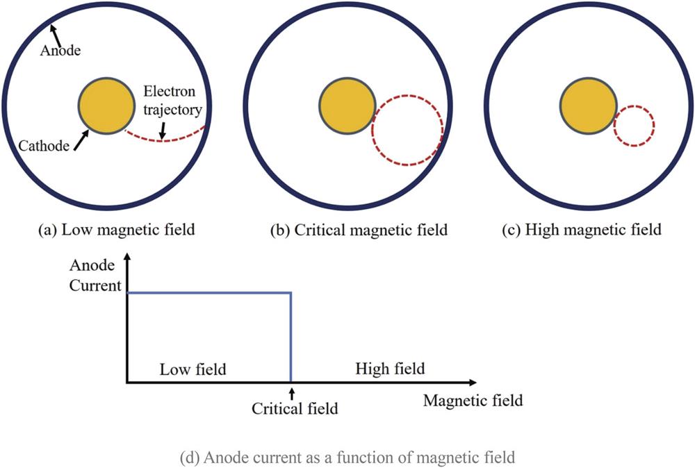
    Fig. 1. Magnetron operation as a function of magnetic field: (a) low magnetic field; (b) critical magnetic field; (c) high magnetic field. (d) Anode current as a function of magnetic field.
    CAD drawing of the original Hull magnetron.
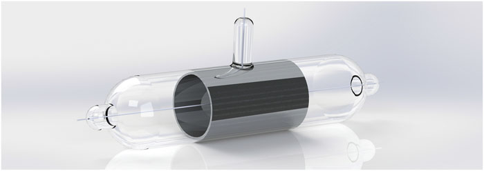
    Fig. 2. CAD drawing of the original Hull magnetron.
    The Hull magnetron circuit. The variables are described in the text. Reprinted with permission from Hull, J. Am. Inst. Electr. Eng. 40, 715–723 (1921). Copyright 1921 IET.
    Fig. 3. The Hull magnetron circuit. The variables are described in the text. Reprinted with permission from Hull, J. Am. Inst. Electr. Eng. 40, 715–723 (1921). Copyright 1921 IET.
    Four-segment magnetron of Slutskin from Kharkiv, Soviet Union. Reprinted with permission from Borisova, in Proceedings of International Conference on the Origins and Evolution of the Cavity Magnetron, Bournemouth, UK, April 2010 (IEEE, 2010), pp. 23–33. Copyright 2010 IEEE.
    Fig. 4. Four-segment magnetron of Slutskin from Kharkiv, Soviet Union. Reprinted with permission from Borisova, in Proceedings of International Conference on the Origins and Evolution of the Cavity Magnetron, Bournemouth, UK, April 2010 (IEEE, 2010), pp. 23–33. Copyright 2010 IEEE.
    The first Ponte decimeter magnetron (λ = 80 cm), 1932. Reprinted with permission from Blanchard, in Proceedings of International Conference on the Origins and Evolution of the Cavity Magnetron, Bournemouth, UK, April 2010 (IEEE, 2010), pp. 5–10. Copyright 2010 IEEE.
    Fig. 5. The first Ponte decimeter magnetron (λ = 80 cm), 1932. Reprinted with permission from Blanchard, in Proceedings of International Conference on the Origins and Evolution of the Cavity Magnetron, Bournemouth, UK, April 2010 (IEEE, 2010), pp. 5–10. Copyright 2010 IEEE.
    The Gutton magnetron (M16) with its permanent magnet. Reprinted with permission from Blanchard, in Proceedings of International Conference on the Origins and Evolution of the Cavity Magnetron, Bournemouth, UK, April 2010 (IEEE, 2010), pp. 5–10. Copyright 2010 IEEE.
    Fig. 6. The Gutton magnetron (M16) with its permanent magnet. Reprinted with permission from Blanchard, in Proceedings of International Conference on the Origins and Evolution of the Cavity Magnetron, Bournemouth, UK, April 2010 (IEEE, 2010), pp. 5–10. Copyright 2010 IEEE.
    The early Philips split anode magnetron. Reprinted with permission from Goerth, in Proceedings of International Conference on the Origins and Evolution of the Cavity Magnetron, Bournemouth, UK, April 2010 (IEEE, 2010), pp. 17–22. Copyright 2010 IEEE.
    Fig. 7. The early Philips split anode magnetron. Reprinted with permission from Goerth, in Proceedings of International Conference on the Origins and Evolution of the Cavity Magnetron, Bournemouth, UK, April 2010 (IEEE, 2010), pp. 17–22. Copyright 2010 IEEE.
    Photograph of an early copy of the cavity magnetron. Reprinted with permission from Brittain, Phys. Today 38, 60–67 (1985). Copyright 1985 AIP Publishing LLC.
    Fig. 8. Photograph of an early copy of the cavity magnetron. Reprinted with permission from Brittain, Phys. Today 38, 60–67 (1985). Copyright 1985 AIP Publishing LLC.
    Historical evolution of the relativistic magnetron (inspired by Fig. 10.1 in Ref. 16 and updated).
    Fig. 9. Historical evolution of the relativistic magnetron (inspired by Fig. 10.1 in Ref. 16 and updated).
    Schematic of the first A6 magnetron at MIT. Reprinted from Palevsky and Bekefi, Phys. Fluids 22, 986–996 (1979). Copyright 1979 AIP Publishing LLC.
    Fig. 10. Schematic of the first A6 magnetron at MIT. Reprinted from Palevsky and Bekefi, Phys. Fluids 22, 986–996 (1979). Copyright 1979 AIP Publishing LLC.
    Dispersion diagram of Bekefi’s A6 magnetron. Reprinted from Palevsky and Bekefi, Phys. Fluids 22, 986–996 (1979). Copyright 1979 AIP Publishing LLC.
    Fig. 11. Dispersion diagram of Bekefi’s A6 magnetron. Reprinted from Palevsky and Bekefi, Phys. Fluids 22, 986–996 (1979). Copyright 1979 AIP Publishing LLC.
    Electric field distribution in an A6 magnetron for π and 2π (or 0) modes. Reprinted from Palevsky and Bekefi, Phys. Fluids 22, 986–996 (1979). Copyright 1979 AIP Publishing LLC.
    Fig. 12. Electric field distribution in an A6 magnetron for π and 2π (or 0) modes. Reprinted from Palevsky and Bekefi, Phys. Fluids 22, 986–996 (1979). Copyright 1979 AIP Publishing LLC.
    Photograph showing the diffraction output of an eight-cavity X-band MDO. Courtesy of Fuks, University of New Mexico (retired), Albuquerque, NM.
    Fig. 13. Photograph showing the diffraction output of an eight-cavity X-band MDO. Courtesy of Fuks, University of New Mexico (retired), Albuquerque, NM.
    Tunable rising-sun relativistic magnetron at Physics International. This relativistic magnetron uses plungers moving back walls of three vanes for mechanical tunability. Extraction is through two waveguide ports, one of which is visible. Reprinted with permission from Benford, in Proceedings of International Conference on the Origins and Evolution of the Cavity Magnetron, Bournemouth, UK, April 2010 (IEEE, 2010), pp. 40–45. Copyright 2010 IEEE.
    Fig. 14. Tunable rising-sun relativistic magnetron at Physics International. This relativistic magnetron uses plungers moving back walls of three vanes for mechanical tunability. Extraction is through two waveguide ports, one of which is visible. Reprinted with permission from Benford, in Proceedings of International Conference on the Origins and Evolution of the Cavity Magnetron, Bournemouth, UK, April 2010 (IEEE, 2010), pp. 40–45. Copyright 2010 IEEE.
    ORION outdoor testing facility when it was operational in the UK. Courtesy of Smith, L-3 Communications (retired), San Leandro, CA.
    Fig. 15. ORION outdoor testing facility when it was operational in the UK. Courtesy of Smith, L-3 Communications (retired), San Leandro, CA.
    MAGIC 3D simulations performed at UNM showing the benefits of a transparent cathode in an A6 relativistic magnetron compared with a solid cathode or projection ablation lithography (PAL) cathode priming. Reprinted with permission from Fuks and Schamiloglu, Phys. Rev. Lett. 96, 205101 (2005). Copyright 2005 American Physical Society.
    Fig. 16. MAGIC 3D simulations performed at UNM showing the benefits of a transparent cathode in an A6 relativistic magnetron compared with a solid cathode or projection ablation lithography (PAL) cathode priming. Reprinted with permission from Fuks and Schamiloglu, Phys. Rev. Lett. 96, 205101 (2005). Copyright 2005 American Physical Society.
    Photograph of the SINUS-6 accelerator at UNM with the A6 magnetron with radial extraction.
    Fig. 17. Photograph of the SINUS-6 accelerator at UNM with the A6 magnetron with radial extraction.
    ORION relativistic magnetron performance with a CsI-coated carbon velvet cathode. The magnetron total current is shown in (a) for three different applied pulse durations, whereas the instantaneous RF electric field measured in an output waveguide is shown in (b). Note that the time scales on the two traces are different. Reprinted with permission from Shiffler et al., IEEE Trans. Plasma Sci. 36, 718–728 (2008). Copyright 2008 IEEE.
    Fig. 18. ORION relativistic magnetron performance with a CsI-coated carbon velvet cathode. The magnetron total current is shown in (a) for three different applied pulse durations, whereas the instantaneous RF electric field measured in an output waveguide is shown in (b). Note that the time scales on the two traces are different. Reprinted with permission from Shiffler et al., IEEE Trans. Plasma Sci. 36, 718–728 (2008). Copyright 2008 IEEE.
    Photograph of the modified PI-110A accelerator (back) adjacent to the SINUS-6 (front) at UNM.
    Fig. 19. Photograph of the modified PI-110A accelerator (back) adjacent to the SINUS-6 (front) at UNM.
    Output power P and efficiency η as functions of magnetic field for an MDO. The critical magnetic field is H00 = 4.527 kOe. Reprinted with permission from Liu et al., Appl. Phys. Lett. 97, 251501 (2010). Copyright 2010 AIP Publishing LLC.
    Fig. 20. Output power P and efficiency η as functions of magnetic field for an MDO. The critical magnetic field is H00 = 4.527 kOe. Reprinted with permission from Liu et al., Appl. Phys. Lett. 97, 251501 (2010). Copyright 2010 AIP Publishing LLC.
    (a) The van der Pol diagram115 of a system with a saddle point F0 between stable states F1 and F2. (b) Ball on top of a hill between two valleys. This mechanical system is an analog for RF mode switching in an MDO. Reprinted with permission from Liu et al., Appl. Phys. Lett. 97, 251501 (2010). Copyright 2010 AIP Publishing LLC.
    Fig. 21. (a) The van der Pol diagram115 of a system with a saddle point F0 between stable states F1 and F2. (b) Ball on top of a hill between two valleys. This mechanical system is an analog for RF mode switching in an MDO. Reprinted with permission from Liu et al., Appl. Phys. Lett. 97, 251501 (2010). Copyright 2010 AIP Publishing LLC.
    Photographs of the UNM compact A6 MDO (a) and the permanent magnet (b). The photograph in (a) shows how the compact MDO radiates a TE11 mode from the generated mode. As is evident, two of the six cavities are closed off and four are opened. The electric fields from the two top open cavities and two bottom open cavities sum to radiate a linearly polarized TE11 mode without requiring the bulk mode converter of the full MDO.
    Fig. 22. Photographs of the UNM compact A6 MDO (a) and the permanent magnet (b). The photograph in (a) shows how the compact MDO radiates a TE11 mode from the generated mode. As is evident, two of the six cavities are closed off and four are opened. The electric fields from the two top open cavities and two bottom open cavities sum to radiate a linearly polarized TE11 mode without requiring the bulk mode converter of the full MDO.
    Photograph of the NUDT permanent magnet relativistic magnetron.121
    Fig. 23. Photograph of the NUDT permanent magnet relativistic magnetron.121
    (a) External view of anode with the angular segment (AS) NdFeB permanent magnets and the anode endcap seen separately. (b) Same as (a), but with the cathode and the anode endcap installed. (c) Long cathode without inserted rod magnets. (d) Short cathode with rod magnets inserted. (e) Same as (c), but with rod magnets inserted. Reprinted with permission from Krasik et al., IEEE Trans. Plasma Sci. 47, 3997–4005 (2019). Copyright 2019 IEEE.
    Fig. 24. (a) External view of anode with the angular segment (AS) NdFeB permanent magnets and the anode endcap seen separately. (b) Same as (a), but with the cathode and the anode endcap installed. (c) Long cathode without inserted rod magnets. (d) Short cathode with rod magnets inserted. (e) Same as (c), but with rod magnets inserted. Reprinted with permission from Krasik et al., IEEE Trans. Plasma Sci. 47, 3997–4005 (2019). Copyright 2019 IEEE.
    Photograph of the RPM-12a planar recirculating magnetron at UM. Courtesy Gilgenbach, University of Michigan, Ann Arbor, MI.
    Fig. 25. Photograph of the RPM-12a planar recirculating magnetron at UM. Courtesy Gilgenbach, University of Michigan, Ann Arbor, MI.
    ParameterConventional magnetronRelativistic magnetron
    Voltage≤100 kV≥500 kV
    Current∼100 A≥5–40 kA
    CathodeThermionic and secondary emissionExplosive emission
    Pulse duration∼1 ms∼100 ns
    Risetime≤200 kV/ms∼100 kV/ns
    Power≤10 MW∼1 GW
    Tunable range∼5%∼30%
    Efficiency∼50%∼20%–40%
    Table 1. Comparison of operational parameters of typical non-relativistic and relativistic magnetrons.16
    Dmitrii Andreev, Artem Kuskov, Edl Schamiloglu. Review of the relativistic magnetron[J]. Matter and Radiation at Extremes, 2019, 4(6): 067201
    Download Citation