Abstract
We propose and demonstrate an agile X-band signal synthesizer with ultralow phase noise based on all-fiber-photonic techniques for radar applications. It shows phase noise of () at 10 kHz (100 kHz) offset frequency for 10 GHz carrier frequency with integrated RMS timing jitter between 7.6 and 9.1 fs (integration bandwidth: 10 Hz–10 MHz) for frequencies from 9 to 11 GHz. Its frequency switching time is evaluated to be 135 ns with a 135 pHz frequency tuning resolution. In addition, the X-band linear-frequency-modulated signal generated by the proposed synthesizer shows a good pulse compression ratio approximating the theoretical value. In addition to the ultrastable X-band signals, the proposed synthesizer can also provide 0–1 GHz ultralow-jitter clocks for analog-to-digital converters (ADC) and digital-to-analog converters (DAC) in radar systems and ultralow-jitter optical pulse trains for photonic ADC in photonic radar systems. The proposed X-band synthesizer shows great performance in phase stability, switching speed, and modulation capability with robustness and potential low cost, which is enabled by an all-fiber-photonics platform and can be a compelling technology suitable for future X-band radars.1. INTRODUCTION
It is expected that photonic techniques will have enormous potential in next-generation radar systems [1]: recently, a radar system that takes advantages of photonics has indeed shown great performance in field demonstration [2]. The heart of the photonics-based radar is the mode-locked laser (MLL) for tunable microwave signal generation and photonic analog-to-digital conversion. Microwave signals with ultralow phase noise can benefit radar systems mainly in the following three aspects. First, lower phase noise can improve detection sensitivity for targets’ velocity based on the Doppler effect [3]. For example, when reducing the phase noise of a 10 GHz oscillator at 70 Hz offset frequency from to , the probability of detection increases from 95% to 100% in a coherent radar for detection of a target with velocity of 4 km/h. On the other hand, if the phase noise is deteriorated to , the probability of detection would degrade to zero [4,5]. The phase noise of the oscillator set the minimum echo power level required for accurate detection [6,7]. Second, lower phase noise improves imaging quality for a synthetic aperture radar because the integrated phase noise of the oscillator manifests itself as a deterioration of the impulse response function [8]. Third, lower phase noise can reduce error vector magnitude (EVM) in orthogonal frequency division multiplexing (OFDM) communication, where the EVM is directly determined by the integrated phase noise of the carrier over a certain offset frequency range [9,10]. As the integration of radar, communications, and electronic warfare functions into one system sharing the same radio frequency (RF) aperture and supporting subsystems is the trend for future operation platforms, the communication quality is critical [11–15]. Besides, OFDM is also used in radar processing to overcome the typical drawbacks of correlation operation processing [16,17].
Aside from low phase noise, agile tunability of the oscillator frequency is also critical, for example, for electronic warfare systems. The probability of interception in electronic reconnaissance could be degraded by frequency hopping, which often requires that the frequency changes 100 times or more in 1 s [18]. Moreover, hopping frequencies are useful in a variety of radar systems as well [19–21]. Typically, in a modern radar system, the phase noise of all frequencies used in the radar system is significant to meet the stringent clutter cancellation requirement, including clocks of an analog-to-digital converter (ADC) and digital-to-analog converter (DAC) [22]. Therefore, a frequency-agile synthesizer with low phase noise over a wide range is highly desirable.
Recently, a forced opto-electronic oscillator was demonstrated for 9–11 GHz frequency synthesis, in which the frequency is tuned by a tunable yttrium iron garnet (YIG) microwave filter and a wavelength-tuned transversal filter for coarse and fine tuning, respectively [23]. The phase noise for 9, 10, and 11 GHz are the same at at 10 kHz offset frequency. Although the scheme has an advantage of frequency-independent phase noise, its frequency switching speed is slow due to the use of two phase-locked loops (PLLs). Besides, the YIG filter is sensitive to the tuning current (25 MHz/mA), and the stability of the tuning current may be a problem for stable operation. A sapphire loaded cavity oscillator as an X-band radar exciter was reported as well. The demonstrated frequency tuning range was from 9.92 to 10.8 GHz, and the coarse and fine tuning are realized by an internal 80 MHz oscillator and an external 320 MHz synthesizer, respectively [24]. The exciter has high spectral purity while being expensive and not commercially available. More recently, a broadband electronic synthesizer was demonstrated on the basis of a stabilized Ti:sapphire laser frequency comb referring to an ultralow-expansion glass-based Fabry–Perot optical cavity. The synthesized X- and W-band signals show great phase stability [25]. However, the whole system has stringent requirements on the operation environment and currently is not suitable for more practical field applications outside a metrology laboratory.
Sign up for Photonics Research TOC. Get the latest issue of Photonics Research delivered right to you!Sign up now
In this paper, an X-band frequency synthesizer built on all-fiber-photonics is proposed and demonstrated. An MLL stabilized to an all-fiber reference is the key element of the system, where an ultrastable 10 GHz microwave signal is extracted using a microwave-photonic phase detector (PD). Then, a direct digital synthesizer (DDS) is driven by a quarter of the ultrastable 10 GHz and enables agile tunability from 9 to 11 GHz after single-sideband (SSB) mixing with the ultrastable 10 GHz. The proposed synthesizer shows excellent phase stability and is good enough for the phase noise specification of model TS3 used by the United States Navy [24] with much lower cost and all commercially available components. Moreover, the stabilized optical pulses could benefit photonic ADCs in a photonics-based radar as well.
2. METHODS AND EXPERIMENTAL DETAILS
Figure 1 shows a diagram of the demonstrated fiber photonics-based X-band frequency synthesizer. The system has three major parts: (i) all-fiber-photonics-based repetition-rate stabilized MLL source; (ii) optical-to-microwave conversion with a fiber-loop optical-microwave (FLOM) PD based PLL; (iii) frequency tuning electronics based on the DDS.
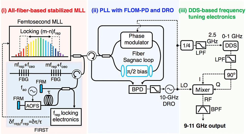
Figure 1.Diagram of the demonstrated all-fiber-photonics-based X-band synthesizer. AOFS, acousto-optic frequency shifter; FBG, fiber Bragg grating; FRM, Faraday rotating mirror; BPD, balanced photodetector; BPF, bandpass filter; LPF, low-pass filter.
A 250 MHz femtosecond mode-locked Er-fiber oscillator (MenloSystems GmbH, FC1500-250-ULN) with ultralow high-frequency timing jitter (175 as RMS timing jitter integrated from 10 kHz to 1 MHz offset frequency, measured in Ref. [26]) is used as the MLL. To achieve ultrahigh phase stability over a wider range of offset frequency down to 10 Hz and lower, the repetition rate of the MLL () is stabilized to a 1 km long fiber delay line using fiber interferometer-based repetition-rate stabilization technique (FIRST) [27]. Two spectral modes at () and () are used for the stabilization, where is the carrier-envelope offset frequency of the MLL output. Here, is effectively eliminated by mixing of () and (). As a result, the frequency noise in can be obtained. This error signal is then applied to repetition-rate-tuning actuators [an electro-optic modulator (EOM) and a piezoelectric transducer (PZT)] inside the MLL cavity. Here, the EOM and PZT are used for fast () and slow () compensation in MLL cavity length, respectively. When the feedback loops are closed, the MLL repetition rate is stabilized to the fiber delay (i.e., , where is the delay time in the fiber link). Note that the fundamental limit in is set by the thermal noise-induced mechanical dissipation [28,29], which is computed as at 0.1 s averaging time. The measured in Ref. [27] is at 0.1 s, which is mostly limited by various technical noise sources. Even this discrepancy, it suppresses the MLL phase noise by at 10 Hz offset frequency and, as shown in Fig. 2, the use of 1 km fiber delay indeed enables the suppression of equivalent phase noise at 10 GHz carrier down to at 10 Hz offset frequency [curve (iii) in Fig. 2].
![Absolute SSB phase noise and integrated timing jitter of the generated microwave signals. Curve (i) [black], phase noise of the 10 GHz DRO locked to the stabilized MLL. Curve (ii) [pink], phase noise floor of the used PNA at 10 GHz carrier frequency. Curve (iii) [blue], projected phase noise at 10 GHz by an optical-domain measurement. Curve (iv) [light purple], residual noise floor of FLOM-PD synchronization. Curve (v) [green], phase noise of the 9 and 11 GHz signals from the synthesizer output. Note that the red area indicates the phase noise range of the DDS output from 10 MHz (bottom red curve) to 1 GHz (top red curve). As a result, the phase noise of the synthesizer output (9–11 GHz) lies between curve (i) (10 GHz) and curve (v) (9 and 11 GHz), indicated as the diagonal patterned area. Curve (vi), integrated timing jitter for curve (i). Curve (vii), integrated timing jitter for curve (iii). Curve (viii), integrated timing jitter for curve (v) at 9 GHz.](/Images/icon/loading.gif)
Figure 2.Absolute SSB phase noise and integrated timing jitter of the generated microwave signals. Curve (i) [black], phase noise of the 10 GHz DRO locked to the stabilized MLL. Curve (ii) [pink], phase noise floor of the used PNA at 10 GHz carrier frequency. Curve (iii) [blue], projected phase noise at 10 GHz by an optical-domain measurement. Curve (iv) [light purple], residual noise floor of FLOM-PD synchronization. Curve (v) [green], phase noise of the 9 and 11 GHz signals from the synthesizer output. Note that the red area indicates the phase noise range of the DDS output from 10 MHz (bottom red curve) to 1 GHz (top red curve). As a result, the phase noise of the synthesizer output (9–11 GHz) lies between curve (i) (10 GHz) and curve (v) (9 and 11 GHz), indicated as the diagonal patterned area. Curve (vi), integrated timing jitter for curve (i). Curve (vii), integrated timing jitter for curve (iii). Curve (viii), integrated timing jitter for curve (v) at 9 GHz.
The next step is extracting ultralow-phase-noise 10 GHz microwave signal from the stabilized MLL with minimal excess phase noise in the optical-to-electrical conversion process. Among several different approaches, including advanced photodetection [30]; here, an optoelectronic PLL with a microwave-photonic phase detector called the FLOM-PD [31,32] and a high-quality dielectric resonator oscillator (DRO, INWAVE DRO-10010) is employed. The use of high-quality DRO as the slave oscillator in the PLL provides an elegant solution for lower phase noise in the high offset frequency by using the flywheel effect of DRO. It can also provide high RF power () directly from the DRO without additional RF amplifiers. The 10 GHz signal from the DRO drives the phase modulator in the Sagnac-loop interferometer and modulates the stabilized optical pulses from the MLL. The relative temporal position between the 10 GHz microwave signal zero-crossings and the optical pulses is reflected in the output of the balanced photodetector (BPD). The output from the BPD is fed back to lock the 10 GHz signal to the stabilized temporal positions of optical pulses.
Finally, for agile and high-resolution frequency tuning, a DDS-based electronics, which has been widely used in radar synthesizers [33], is employed. In order to keep ultralow phase noise of the synthesizer over the entire 9–11 GHz range, the DDS (Analog Devices, AD9914) is driven by a 2.5 GHz signal obtained from the frequency division of the 10 GHz signal generated from the locked DRO. In this case, the DDS can generate signals up to 1 GHz. Note that the used DDS supports clocking up to 3.5 GHz and its frequency tuning resolution is 135 pHz when driven by a 2.5 GHz clock. In addition, it is capable of phase and amplitude modulation, output shift keying, and sweeping of phase, frequency, and amplitude. Then, the DDS output is mixed with the stabilized 10 GHz DRO to obtain 9–11 GHz tunable microwave signals with the assistance of an SSB mixer and a 90° hybrid for local oscillator and image frequency suppression. The selection of upper or lower sideband can be achieved by switching I and Q outputs of the 90° hybrid to I and Q inputs of the SSB mixer. The 90° hybrid supports signals from 10 MHz to 1 GHz, the IQ mixer (Analog Devices, HMC-C042) works with intermediate frequency up to 2 GHz and the frequency divider (RF Bay Inc, FPS-4-13) has noise floor of at 100 kHz.
Note that, compared with our previous works on fiber interferometer-based repetition-rate stabilization [27] and laser-microwave synchronization [31,32], this work combines these two techniques and demonstrates ultralow-phase-noise microwave signal generation from an all-fiber-photonic system. Furthermore, by adding a DDS-based frequency-tuning electronics, a frequency tunable X-band synthesizer is realized. To our knowledge, this is the first work to evaluate all major properties important for radar sources (such as phase noise, frequency switching speed, spur suppression, and modulation capability) and achieve state-of-the-art performances for a fiber photonics-based microwave synthesizer.
3. RESULTS AND DISCUSSIONS
The performance of our fiber photonic X-band frequency synthesizer is evaluated in terms of phase stability, frequency-switching speed, spur suppression ratio, and modulation capability.
First, we measured the absolute SSB phase noise of the generated microwave signals using a high-sensitivity phase noise analyzer (PNA, FSWP50 from R&S). Figure 2 summarizes the phase noise performances. Curve (i) [black] shows the phase noise of the 10 GHz microwave signal generated from the DRO locked to the fiber-delay-stabilized Er-fiber MLL. In fact, this phase noise measurement result is already limited by the PNA instrument sensitivity in the low offset frequency range (10 Hz–1 kHz) [curve (ii), pink]. The actual phase noise of the 10 GHz signal can be projected by the optical-domain measurement [27] result [curve (iii), blue], which is lower in the low offset frequency. Note that the MLL repetition-rate phase noise can be measured with resolution at 10 Hz offset frequency when using a long fiber delay line-based interferometer as an out-of-loop frequency discriminator [27]. In the 10 kHz–2 MHz offset frequency range, the phase noise follows the noise floor of the FLOM-PD [curve (iv), light purple] at () at 10 kHz (100 kHz) offset frequency. Above 2 MHz offset frequency (which is the locking bandwidth between the MLL and the DRO), the phase noise follows that of the free-running DRO and rapidly decreases to at 10-MHz offset frequency. The resulting absolute RMS timing jitter of the 10-GHz signal [curve (vi); integration of curve (i)] is 7.6 fs integrated from 10 Hz to 10 MHz, which is limited by the PNA sensitivity. The actual timing jitter [curve (vii); integration of curve (iii)] is expected to be much lower, 2.6 fs in the same integration bandwidth.
The red area indicates the measured phase noise range of the DDS output in the 10 MHz–1 GHz range, where the lowest and highest levels indicate the phase noise at 10 MHz and 1 GHz, respectively. Because the DDS output is the frequency division of the clock signal, the phase noise of DDS output scales down with a factor of (dB) on basis of the clock signal, where denotes the frequency division factor. As the DDS residual phase noise increases with output frequency, the DDS phase noise becomes higher than the locked DRO noise for offset frequency range when the DDS output frequency is higher than 400 MHz.
The phase noise range of the final frequency synthesizer output (9–11 GHz), which is obtained by the frequency mixing of the DRO output (10 GHz) with the DDS output (0–1 GHz), is indicated as the diagonal patterned area in Fig. 2. Due to the increase in phase noise for higher-frequency DDS output, the phase noise at 9 and 11 GHz is the worst, while the phase noise at 10 GHz is the lowest. Even in the worst case, the phase noise is still extremely low, () at 10 kHz (100 kHz) offset frequency for 9 and 11 GHz. The timing jitter of 9–11 GHz signal integrated from 10 Hz to 10 MHz offset frequency is still low, in the range of 7.6 fs (at 10 GHz) to 9.1 fs (at 9 GHz). If the phase noise measurement is not limited by PNA, the jitter value will be in the range of 2.6 to 4.2 fs. Note that the measured phase noise below 1 kHz offset frequency is independent of DDS output frequency and is limited by the PNA measurement sensitivity and fiber reference stability.
Second, to characterize the agility of our synthesizer, we evaluated the frequency switching time. The oscilloscope with 80 GSa/s sampling rate (Keysight, MSOV334A) is used to capture the moment that frequencies transit and settle. The DDS is set to change the output frequency from 100 MHz to 1 GHz. The waveform recording frequency transition and settling process is captured (inset of Fig. 3) and used to extract the unwrapped phase after filtering out the added high-frequency noise in the sampling process. The Hilbert transform is used to obtain analytic signals of the measured data, and then the unwrapped phase of the analytic signals is obtained to get the final phase error over time [34], as shown in Fig. 3. Note that, generally, the frequency switching time (from to ) is defined as the time starting from the phase error with respect to frequency exceeds 0.1 rad and ending in the phase error with respect to frequency is within 0.1 rad. On the premise that the oscilloscope has trigger jitter of 100 fs, which causes about phase instability to 1 GHz signal, and the vertical sensitivity (2.1 mV for 50 mV/div) corresponds to phase uncertainty for our signal with 400 mV peak-to-peak voltage (100 mV/div), a reliable evaluation of the frequency transition and settling time is 7.8 ns. Together with the data latency inside the DDS for frequency setting (127.2 ns), the frequency switching time is evaluated to be 135 ns for our synthesizer. The sub-microsecond-level frequency switching time can easily meet the frequency-hopping speed requirement in the electronic warfare communication systems [18].
Figure 3.Phase error during frequency transition and settling process. Inset, waveform captured by the oscilloscope at the moment that frequencies transit and settle.
Third, the spur suppression ratio is evaluated. Intrinsic spurs in the output spectrum have been regarded as a drawback of the DDS-based synthesizer. Because spurs are not only decided by the DDS design but also from the reference clock, spurs in the clock signal will appear as spurs in DDS output at the same offset frequency [35]. Therefore, the spur suppression ratios are measured from 50 MHz to 1 GHz DDS output frequency range over 1.25 GHz span for our synthesizer, as shown in Fig. 4. The worst case is 58 dBc measured at 500 MHz, and its spectrum is shown in the inset of Fig. 4. Thanks to the advances in electronics and signal processing, many solutions based on both hardware and software to reduce spurs are available because spurs are predictable for a given frequency [33,36].
Figure 4.Spur suppression ratio for 50 MHz–1 GHz output range in 1.25 GHz span. Inset, the spectrum for 500 MHz output.
Finally, the proposed synthesizer is capable of modulations that meet demands of most radar applications. The generation of the most commonly used radar waveform, linear frequency-modulated (LFM) signal, is demonstrated. Because phase errors in the LFM signal directly affect the accuracy of achievable distance estimation in linear frequency-modulated continuous-wave (FMCW) radars [37], a synthesizer with low phase noise is highly desirable. In our demonstration, the DDS sweeps frequencies from 500 MHz to 1 GHz with a step of 10 MHz and time interval of 10 ns and then mixes with the stabilized 10 GHz. The LFM waveform is recorded by the oscilloscope (Keysight, MSOV334A) and used to recover the instantaneous frequency, as shown in Fig. 5(a). The autocorrelation of the LFM waveform shows a 2.9-ns 3-dB pulse width [Fig. 5(b)] and corresponds to 22.4 dB pulse compression ratio (PCR). There is 1.5 dB deterioration in PCR compared with the theoretical value, which is primarily due to the application of windowing function [38,39]. Besides, range side lobe in Fig. 5(b) is relatively high, which is attributed to the amplitude unevenness over the frequency range of the LFM signal [40]. An amplitude control unit would solve this problem.
Figure 5.(a) Recovered instantaneous frequency of LFM signal increased from 10.5 to 11 GHz in 500 ns. (b) Autocorrelation of the LFM signal in (a).
4. CONCLUSION
We propose and demonstrate an ultralow-phase-noise and agile X-band signal synthesizer based on all-fiber-photonic techniques for radar applications. It shows phase noise of () at 10 kHz (100 kHz) offset frequency for 10 GHz. The measured integrated RMS timing jitter (10 Hz–10 MHz) is between 7.6 to 9.1 fs for frequencies from 9 to 11 GHz. Note that the measured phase noise is limited by the measurement instrument sensitivity in the offset frequency, and the projected jitter is even lower in the 2.6–4.2 fs range. Note that the use of longer fiber delay in the FIRST system enables even lower phase noise, for example, at 10-Hz offset frequency as shown in Ref. [41]. Apart from ultralow phase noise, it is capable of sub-microsecond-level frequency switching and 135 pHz frequency tuning resolution as well. Besides, the X-band LFM signals generated by our synthesizer shows a good PCR approximating the theoretical value. In addition to ultrastable X-band signals, our method can also provide 0–1 GHz ultralow-jitter clocks for ADC and DAC in radar systems and ultralow-jitter optical pulses for photonic ADC in a photonic radar system as well. The X-band synthesizer demonstrated in this work shows great performance in phase stability, switching speed, and modulation capability with robustness and potential low-cost, which is enabled by all-fiber-photonics platform and can be a compelling technology suitable for future X-band radars.
Acknowledgment
Acknowledgment. J. Wei acknowledges the financial support from the CSC for visiting research at KAIST.
References
[1] P. Ghelfi, F. Laghezza, F. Scotti, G. Serafino, A. Capria, S. Pinna, D. Onori, C. Porzi, M. Scaffardi, A. Malacarne, V. Vercesi, E. Lazzeri, F. Berizzi, A. Bogoni. A fully photonics-based coherent radar system. Nature, 507, 341-345(2014).
[2] J. D. McKinney. Photonics illuminates the future of radar. Nature, 507, 310-312(2014).
[3] I. S. Merrill. Introduction to Radar Systems(2001).
[4] J. R. Vig. Introduction to quartz frequency standards(1992).
[5] J. Taylor. Effects of crystal reference oscillator phase noise in a vibratory environment(1980).
[6] D. B. Leeson. Oscillator phase noise: a 50-year review. IEEE Trans. Ultrason. Ferroelectr. Freq. Control, 63, 1208-1225(2016).
[7] M. Jankovic. Phase noise in microwave oscillators and amplifiers(2010).
[8] G. Krieger, M. Younis. Impact of oscillator noise in bistatic and multistatic SAR. IEEE Geosci. Remote Sens. Lett., 3, 424-428(2006).
[9] T. Pollet, M. Vanbladel, M. Moeneclaey. BER sensitivity of OFDM systems to carrier frequency offset and Wiener phase noise. IEEE Trans. Commun., 43, 191-193(1995).
[10] A. G. Armada. Understanding the effects of phase noise in orthogonal frequency division multiplexing (OFDM). IEEE Trans. Broadcast., 47, 153-159(2001).
[11] M. Jamil, H.-J. Zepernick, M. I. Pettersson. On integrated radar and communication systems using Oppermann sequences. IEEE Military Communications Conference, 1-6(2008).
[12] G. C. Tavik, C. L. Hilterbrick, J. B. Evins, J. J. Alter, J. G. Crnkovich, J. W. de Graaf, W. Habicht, G. P. Hrin, S. A. Lessin, D. C. Wu, S. M. Hagewood. The advanced multifunction RF concept. IEEE Trans. Microwave Theory Tech., 53, 1009-1020(2005).
[13] J. A. Molnar, I. Corretjer, G. Tavik. Integrated topside-integration of narrowband and wideband array antennas for shipboard communications. IEEE Military Communications Conference, 1802-1807(2011).
[14] P. H. Zhao. The technologies of multifunction integrated RF system. Radar ECM, 3, 9-13(2011).
[15] L. Peruzzi. Integrated masts and EW: present and future solutions in Europe. J. Electron. Def., 37, 24-26(2014).
[16] C. Sturm, T. Zwick, W. Wiesbeck. An OFDM system concept for joint radar and communications operations. IEEE Vehicular Technology Conference, 1-5(2009).
[17] Y. L. Sit, C. Sturm, L. Reichardt, T. Zwick, W. Wiesbeck. The OFDM joint radar-communication system: an overview. 3rd International Conference on Advances in Satellite and Space Communications, 69-74(2011).
[18] R. A. Poisel. Introduction to Communication Electronic Warfare Systems(2008).
[19] A. R. Hunt. Use of a frequency-hopping radar for imaging and motion detection through walls. IEEE Trans. Geosci. Remote Sens., 47, 1402-1408(2009).
[20] C. Y. Chen, P. P. Vaidyanathan. MIMO radar ambiguity properties and optimization using frequency-hopping waveforms. IEEE Trans. Signal Process., 56, 5926-5936(2008).
[21] P. Ghelfi, F. Scotti, F. Laghezza, A. Bogoni. Phase coding of RF pulses in photonics-aided frequency-agile coherent radar systems. IEEE J. Quantum Electron., 48, 1151-1157(2012).
[22] M. I. Skolnik. Radar Handbook(2008).
[23] T. Sun, L. Zhang, A. K. Poddar, U. L. Rohde, A. S. Daryoush. Frequency synthesis of forced opto-electronic oscillators at the X-band. Chin. Opt. Lett., 15, 010009(2017).
[24] L. Hoover, H. Griffith, K. DeVries. Low noise X-band exciter using a sapphire loaded cavity oscillator. IEEE International Frequency Control Symposium, 309-311(2008).
[25] T. M. Fortier, A. Rolland, F. Quinlan, F. N. Baynes, A. J. Metcalf, A. Hati, A. D. Ludlow, N. Hinkley, M. Shimizu, T. Ishibashi, J. C. Campbell, S. A. Diddams. Optically referenced broadband electronic synthesizer with 15 digits of resolution. Laser Photon. Rev., 10, 780-790(2016).
[26] D. Kwon, C. G. Jeon, J. Shin, M. S. Heo, S. E. Park, Y. Song, J. Kim. Reference-free, high-resolution measurement method of timing jitter spectra of optical frequency combs. Sci. Rep., 7, 40917(2017).
[27] K. Jung, J. Kim. All-fibre photonic signal generator for attosecond timing and ultralow-noise microwave. Sci. Rep., 5, 16250(2015).
[28] L. Duan. Intrinsic thermal noise of optical fibers due to mechanical dissipation. Electron. Lett., 46, 1515-1516(2010).
[29] K. H. Wanser. Fundamental phase noise limit in optical fibers due to temperature fluctuations. Electron. Lett., 28, 53-54(1992).
[30] T. M. Fortier, F. Quinlan, A. Hati, C. Nelson, J. A. Taylor, Y. Fu, J. Campbell, S. A. Diddams. Photonic microwave generation with high-power photodiodes. Opt. Lett., 38, 1712-1714(2013).
[31] K. Jung, J. Kim. Subfemtosecond synchronization of microwave oscillators with mode-locked Er-fiber lasers. Opt. Lett., 37, 2958-2960(2012).
[32] K. Jung, J. Shin, J. Kim. Ultralow phase noise microwave generation from mode-locked Er-fiber lasers with subfemtosecond integrated timing jitter. IEEE Photon. J., 5, 1-7(2013).
[33] T. J. Endres, R. B. Hall, A. M. Lopez. Design and analysis methods of a DDS-based synthesizer for military spaceborne applications. IEEE International Frequency Control Symposium, 624-632(1994).
[34] B. G. Anderson. Frequency switching time measurement using digital demodulation. IEEE Trans. Instrum. Meas., 39, 353-357(1990).
[35] D. Brandon. Determining if a spur is related to the DDS/DAC or to some other source.
[36] A. Chenakin. Frequency synthesis: current solutions and new trends. Microwave J., 50, 256-260(2007).
[37] M. Pichler, A. Stelzer, P. Gulden, C. Seisenberger, M. Vossiek. Phase-error measurement and compensation in PLL frequency synthesizers for FMCW sensors- I: context and application. IEEE Trans. Circuits Syst. I, 54, 1006-1017(2007).
[38] A. Lewandowski, K. Kucy, D. Startek. High-speed DDS-based generator of pulses with an arbitrary frequency modulation. International Conference on Microwaves, Radar & Wireless Communications, 125-128(2006).
[39] C. Cook. Radar Signals: An Introduction to Theory and Application(2012).
[40] W. Y. Z. Zhimin. Effect of LFM signal flatness on pulse compression performance. Radar Sci. Technol., 2, 100-103(2003).
[41] D. Kwon, J. Kim. All-fiber interferometer-based repetition-rate stabilization of mode-locked lasers to 10−14-level frequency instability and 1-fs-level jitter over 1-s. Opt. Lett., 309718.


