Xiahui Zeng, "Configuration optimization of off-axis parabolic mirror for enhancing the focusability of a laser beam," Chin. Opt. Lett. 19, 032601 (2021)
Copy Citation Text
We demonstrate a configuration optimization process of an off-axis parabolic mirror to maximize the focused peak intensity based on a precise knowledge of the tight focusing properties by using a full vector-diffraction theory and obtain an optimum configuration scaling rule, which makes it possible to achieve the maximum peak intensity. In addition, we also carry out an assessment analysis of the offset and off-axis angle tolerances corresponding to a 5% drop of the maximum focused peak intensity and present scaling laws for the tolerances of the offset and off-axis angle. Understanding these scaling laws is important to enhance the focusability of a laser beam by an off-axis parabolic mirror in the optimum configuration, in particular, which is valuable for structural design and selection of an off-axis parabolic mirror in ultrashort and ultraintense laser–matter interaction experiments.
As an off-axis side segment of a centered parabolic mirror (PM), an off-axis PM (OAP) combines the achromatic and diffraction limited imaging/focusing properties with the advantage of allowing more interactive space around the focal point without disrupting the beam, which is used for light collimation and collection[1–4], imaging[5–8], and focusing[9–11]. Especially, in order to avoid the undesired nonlinear and dispersive effects induced on the pulsed beam by transmissive focusing optics, an OAP has now become an essential device to focus broadband and ultrashort lasers[12–20].
Obtaining as high focused intensity as possible by using an OAP is one of the hotspots in the community active in the field of ultraintense laser–matter interaction. The University of Michigan team obtained a focused peak intensity of by focusing a 45 TW laser beam with an OAP in 2004[16], which was upgraded to by focusing a 300 TW laser beam into 1.3 µm with an OAP[17]. In 2017, a focused peak intensity of was achieved by focusing a 300 TW laser beam with an OAP[18]. In 2018, a focused peak intensity of was achieved by focusing a 5.4 PW laser beam with an OAP[19]. In 2019, a focused peak intensity of was achieved by focusing a 3.0 PW laser beam with an OAP[20]. Although they obtained the maximum focused peak intensity in the contemporary era, they did not take into account whether the OAP as an aberration free optical focusing element was the optimum configuration. To the best of our knowledge, there is no literature reporting the optimal design of an OAP for achieving the maximum focused peak intensity.
In order to obtain the optimal geometry of an OAP, a precise knowledge of the tight focusing properties of OAPs is essential, because the knowledge of the focusing characterizations of OAPs is the necessary prerequisite to optimize geometry of OAPs for enhancing the off-axis focusability of a laser beam. For accurately describing focusing properties of such a nonparaxial beam, especially when the tight focusing effect is considered, a vector-diffraction theory is taken as a rigorous tool[21,22], which is because the vector properties of light not only affect the local field direction but also the intensity distribution at the focus. Moreover, the expressions of its electromagnetic field have to satisfy Maxwell’s four equations beyond the paraxial regime. As matter of fact, the first discussion on focusing properties of an OAP dates back to 1979 when Howard obtained the field intensity distribution at the focus in the framework of ray optics[11]. However, until 2005, the University of Rochester team reported the vector characterizations of the focal field formed by an OAP based on the Stratton–Chu integral formula[23]. Recently, a more detailed theoretical study of the vectorial field focusing properties of an OAP was reported[24].
Sign up for Chinese Optics Letters TOC. Get the latest issue of Chinese Optics Letters delivered right to you!Sign up now
In this Letter, we first demonstrate the electromagnetic field intensity distribution focused by an OAP based on a full vector-diffraction theory. Then, the effects of different focusing and off-axis parabola parameters on the focusing characterizations are investigated. Finally, we will demonstrate the optimization process of the OAP geometry in order to maximize the focused peak intensity and carry out an assessment analysis of the OAP offset and off-axis angle tolerances corresponding to a 5% drop of the maximum focused peak intensity.
2. Theoretical Model
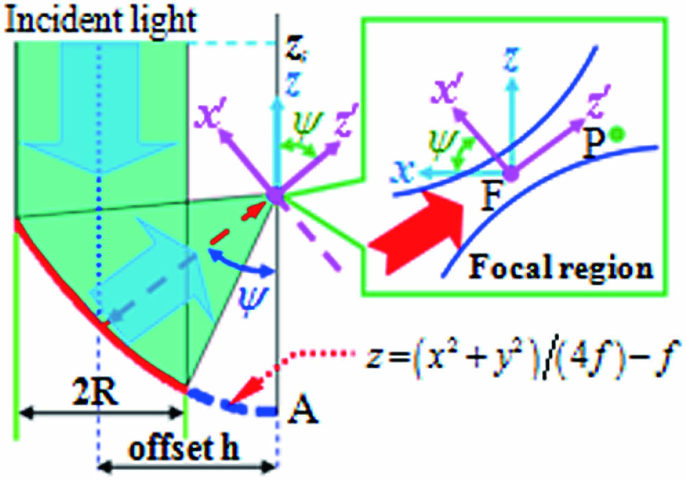
We first explain the principles of the configuration optimization of an OAP via a theoretical calculation. The OAP is the off-axis part of a parent paraboloid , with its axis of revolution symmetry coinciding with the axis and its geometrical focus F coinciding with the origin of a Cartesian coordinate system , as shown in Fig. 1. The apex A of the parent paraboloid is in the negative direction with a distance ( being the parent focal length of the OAP) below the origin. The meridional (sagittal) plane is thus the plane (). The region of the parent paraboloid making up the OAP surface is specified as and , where is the distance from the axis to the center of the incident beam, and is the greatest transverse width of the paraboloid. We call the offset. It is noted that the usable area with is an on-axis paraboloidal surface (i.e., PM). To analyze exactly the focusing vector-electromagnetic field structure after off-axis paraboloidal reflection in the observation plane, it is useful to introduce a new Cartesian coordinate system . Let the direction of propagation of the focusing beam reflected by the paraboloidal surface coincide with the axis of the new coordinate system , as shown in Fig. 1. The new coordinate system is obtained by rotating the coordinate system with an angle around the axis. Here, is also called the OAP off-axis angle.
Figure 1.Schematic illustration of reflection of the OAP and sketch of the Cartesian coordinate systems S (x, y, z) and S′(x′,y′,z′). Focus F of the OAP coincides with origins of the Cartesian coordinate systems. Inset shows beam propagation in the vicinity of focus F.
To calculate the vector-diffraction field of monochromatic light from the OAP, we assume that the incoming beam is propagating in the negative direction, is linearly polarized, and does not have longitudinal components for both electric and magnetic fields, as shown in Fig. 1, so the assumed incident field is given by where is the wave number and is related to the angular temporal frequency of the beam by , and is the speed of light. is the intrinsic impedance of the medium, belongs to the position of the incident plane, and and represent the spatial envelope of the light in the and directions, respectively.
Assuming that the incident wave is reflected only once with a perfect (100%) reflection on the off-axis paraboloidal surface, as reported in the previous work[24], we can obtain the analytical expressions of the electric and magnetic fields in the focal region from an OAP by employing the Stratton–Chu vector-diffraction integrals and the physical optics approximation. These are determined via a surface integral over the OAP and can be expressed as where , , , , and are the coordinates of any observation point P in the vicinity of the geometric focus of the OAP in the Cartesian system , , , and . Here, we use the direction cosines as integral variables. As a result, the Jacobian of the transformation can be expressed by
3. Results and Discussions
Figure 2 shows the electromagnetic field components and the intensity distributions of total field in the focal plane () for a linearly polarized incident wave along the direction focused by OAPs with and , where the parabola -number () is defined by , and and . Note that unless otherwise stated, the incident wave is assumed be an linear polarized beam, that is . The intensity distributions of six vector electric–magnetic field components generated by the OAP with (i.e., on-axis PM) are symmetric, meaning that the cross-sectional amplitude distribution of at any distance () is similar to the distribution, is similar to , and a 90° rotated is similar to , as shown in Figs. 2(a1)–2(a8). However, the intensity distributions of the focused electromagnetic fields formed by OAPs change significantly with the increase of the offset , which will destroy this field component’s symmetry. This effect can be seen from the results shown in Figs. 2(b1)–2(b8). The results shown in Fig. 2 clearly indicate that the characteristics of the focused electromagnetic field formed by OAPs with the same parabola -number are strongly dependent on the offset .
Figure 2.Electromagnetic field intensity distributions focused by f/0.5 OAPs with h = 0 for (a1) , (a2) , (a3) , (a4) , (a5) , (a6) , (a7) , (a8) , and h = 360 mm for (b1)–(b8) with corresponding electromagnetic field components and the total field to (a1)–(a8).
Figure 3 further demonstrates the strong dependence of the transverse intensity distribution, the peak intensity of the three electric field components, and the total field in the focal plane on the offset . From the results shown in Figs. 3(a) and 3(e), it is easily seen that the intensity of first decreases and then increases as increases. This observation can be understood by the fact that a central main lobe is split into two lobes first, and then the two main lobes are combined into one with increasing . In contrast, the intensities of , , and first increase and then decrease as increases, which is verified by Figs. 3(b)–3(e). This change of the electric field components will result in the so-called “depolarized” state[25]. More detailed descriptions of the polarization state variation of an electromagnetic wave focused by an OAP in the focal plane have been reported by Labate et al.[26]. The total intensity distributions along the axis in the cross section for various offsets are shown in Fig. 3(f) along with the intensity distributions of the transverse and longitudinal field components. To present the effect of the OAP offset on the field intensity more clearly, a view of the intensity profiles for and 234 mm in the lateral position between and is displayed in the insets of Fig. 3(f) labeled Figs. 3(g) and 3(h), respectively. From Fig. 3(f), it is clearly observed that the focal spot size increases with increasing , because the focal spot size is proportional to the effective -number of the focusing optics. Note that the effective -number is defined by , where denotes the effective focal length of the OAP, and it increases with increasing [24]. However, for the OAP with and , the maximum peak intensity is achieved at a particular value of , rather than at , which is resulted from the increasing strength of the longitudinal field . Evidence for the strong longitudinal electric field at the focus for is that the intensity profile shows a strong peak along the propagation direction in the focal plane [Fig. 3(g)]. The focus is clearly dominated by the longitudinal field, with a weak contribution from the transversal fields. In contrast, the intensity profile for has a minimum longitudinal field component in the propagation direction [Fig. 3(h)], and the focus is dominated by the transversal field .
Figure 3.Focused electric field intensity transverse distributions of (a) , (b) , (c) , (d) , and (e) peak intensity as functions of offset h, and (f) total field for different h of 0 mm, 150 mm, 234 mm, and 360 mm. (g)(h) Intensity profiles for h = 0 and 234 mm in the lateral position between −3λ and 3λ.
Figure 4 presents the peak intensity of the total field focused by the OAPs with different parent focal length as a function of the offset for various aperture sizes of 80 mm, 120 mm, and 160 mm. The results shown in Fig. 4 clearly indicate that the peak intensity is a strong function of the offset and the aperture size , and the maximum peak intensity is achieved by the OAP with a particular value of about . The corresponding configuration of the OAP is optimum. To more clearly reveal the dependence of this particular value of the offset when the maximum peak intensity occurs upon the parent focal length and the aperture size , we run different sets of simulations and plot the ratio of these particular values of the offset () to the corresponding aperture sizes as a function of the parabola -number. As is clear from Fig. 5, the ratio value quickly decreases as the -number decreases when the -number , even when the -number . However, when the -number , the ratio value slowly increases as the -number increases, until . These plots were fitted with a curve of the type of where the retrieved coefficients are , , and . These coefficients basically provide a scaling law for optimum OAP offset to achieve the maximum peak intensity as a function of the parabola -number.
Figure 4.Peak intensity of electric total field focused by OAPs with different f as a function of offset h for various aperture sizes R of (a) 80 mm, (b) 120 mm, and (c) 160 mm. The dotted line represents the position of h = 1.25R.
Finally, we carry out an assessment analysis of the OAP offset and off-axis angle tolerances corresponding to a 5% drop of the maximum focused peak intensity. The OAP offset (off-axis angle) resulting in a 5% drop of the maximum focused peak intensity () is called the “critical offset” (“critical off-axis angle”). The OAP offset (off-axis angle) tolerance is assessed by the difference between the maximum critical offset (off-axis angle) and the minimum one. It is noted that the minimum OAP offset (off-axis angle) may be the minimum critical offset (off-axis angle), resulting in a 5% drop of the maximum focused peak intensity, or it may be (), but in most situations it is the latter due to the peak intensity for being larger than 95% . So, the OAP offset (off-axis angle) tolerance can be characterized by the maximum critical offset (off-axis angle ). The dependences of the OAP offset tolerance as a function of the parabola -number for various parent focal lengths are plotted in Fig. 6(a). It is clearly visible that the OAP offset tolerance quickly increases as the -number decreases when . However, when , the OAP offset tolerance slowly decreases as the -number increases. The plots of the maximum critical offset were fitted with a nonlinear function: where and . These coefficients also provide a scaling law for the tolerance of the offset to a 5% decrease of the maximum focused peak intensity as a function of the parabola -number. A similar trend is found for the OAP off-axis angle tolerance. The dependence of the OAP off-axis angle tolerance on the parabola -number for various parent focal lengths is shown in Fig. 6(b), and it is fitted with a rational function: where , , and , which provides a scaling law for the tolerance of the off-axis angle to a 5% drop of the maximum focused peak intensity as a function of the parabola -number.
Figure 6.Tolerances of (a) OAP offset and (b) off-axis angle to a 5% decrease of the maximum focused peak intensity as functions of the parabola f-number.
In summary, we have demonstrated an optimization process of OAP geometry to maximize the focused peak intensity based on a precise knowledge of the tight focusing properties of OAPs and have obtained an optimum configuration scaling rule, which makes it possible to achieve the maximum peak intensity. In addition, we have also carried out an assessment analysis of the OAP offset and off-axis angle tolerances corresponding to a 5% drop of the maximum focused peak intensity and have presented scaling laws for the tolerances of the OAP offset and off-axis angle. Understanding these optimization processes and scaling laws is of great significance to enhance the focusing performance of the OAP in the optimal configuration, especially for the structural design and selection of OAPs in ultrashort and ultraintense laser–matter interaction experiments.
Xiahui Zeng, "Configuration optimization of off-axis parabolic mirror for enhancing the focusability of a laser beam," Chin. Opt. Lett. 19, 032601 (2021)