- Infrared and Laser Engineering
- Vol. 49, Issue 7, 20190469 (2020)
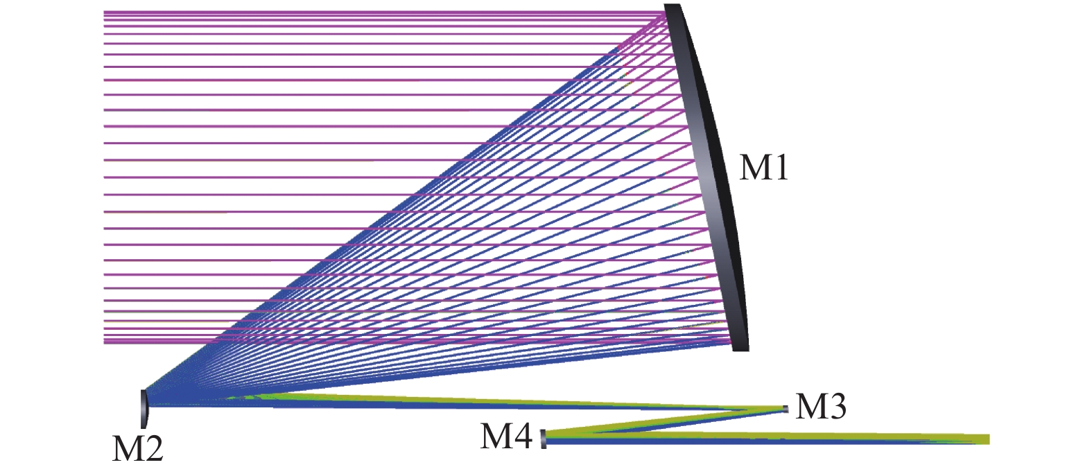
Fig. 1. Optical design scheme solid model
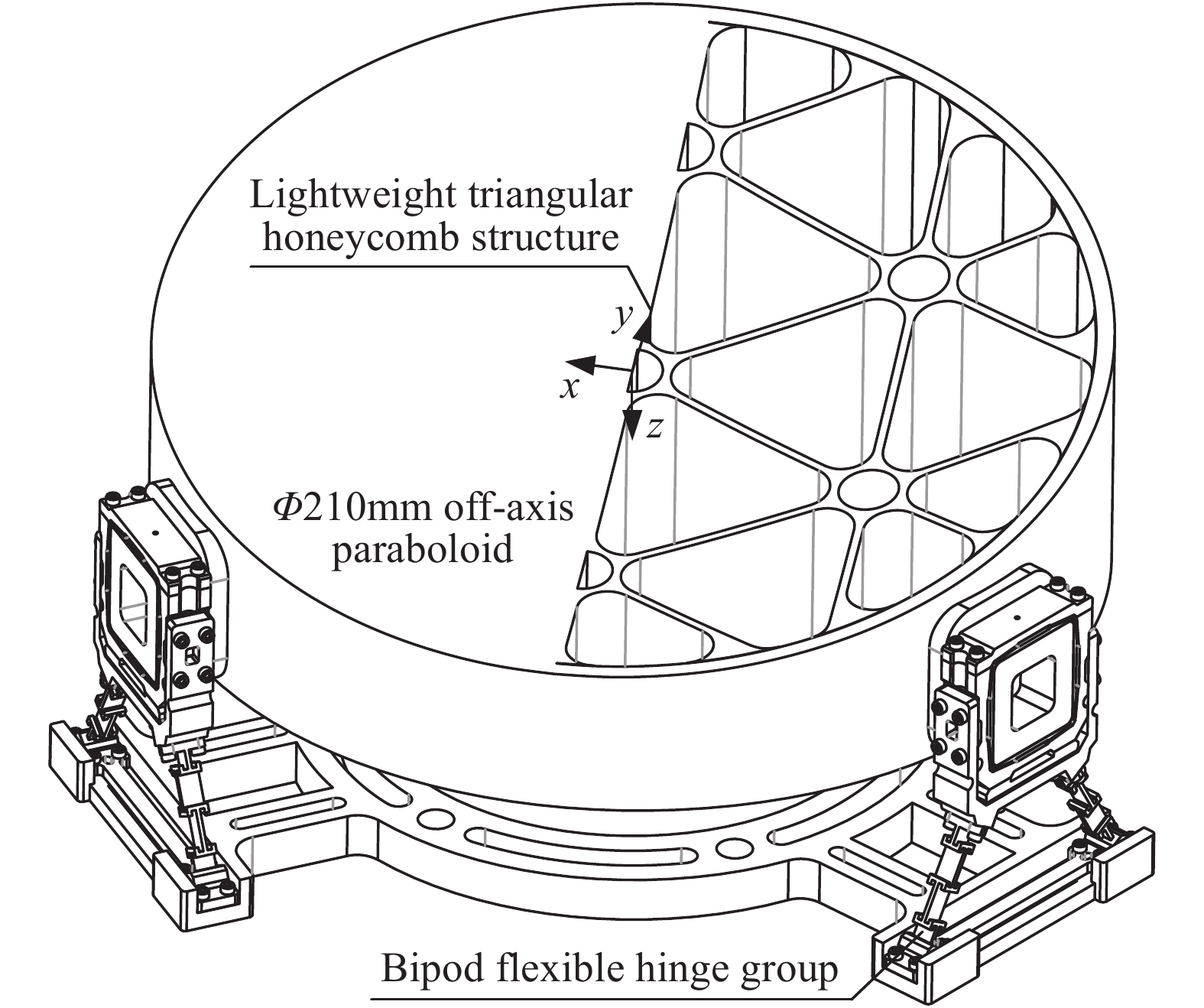
Fig. 2. Primary mirror system of space gravitational telescope
Fig. 3. Schematic diagram of the layout of mirror support structure
Fig. 4. Influence of vertex angle values of different layout types on mirror profile and offset
Fig. 5. Design model of initial parameters for off-axis parabolic primary mirror
Fig. 6. Mirror optimization iteration parameter tradeoff chart
Fig. 7. Solid structure diagram of Bipod flexible hinge group
Fig. 8. Schematic diagram of non-blocking full flexible hinge group
Fig. 9. Flexible support structure model of mirror assembly
Fig. 10. Deformation nephogram of optomechanical structure caused by space thermal load and gravity release
Fig. 11. Surface error under different thermal loads
| ||||||||||||||||||||
Table 1. Material properties of primary mirror components
| |||||||||||||||||||||||||||||||||||||||||||||||||||||||||||
Table 2. Optomechanical design parameters for lightweight mirror
|
Table 3. Mirror optimization parameter value after mirror optimization iteration
|
Table 4. Dimensional parameters of Bipod components
| |||||||||||||||||
Table 5. Modal of the primary mirror system
| |||||||||||||||||||||||||||||||||||||||||||||||||
Table 6. Mirror shape under thermal load conditions

Download Citation

Set citation alerts for the article
Please enter your email address
© Copyright 2018-2021 | Chinese Laser Press. All Rights Reserved 沪ICP备15018463号-20