Abstract
The chimera state is the concurrent combination of synchronous and incoherent oscillations in a set of identical oscillators. In this study, we demonstrate the states for optical nanoresonators where the oscillators are designed based on a plasmonic dimer cavity. This resonator interchanges radiative energy with an active medium located at its hotspot, and therefore forms an amplitude-mediated oscillating system. Finite-difference time-domain (FDTD)-based numerical analysis of a circular array of the coupled oscillators reveals that regardless of identical nature, oscillator phase is not concordant over time for all members. The effect of coupling strength on the phase escape/synchronization of the oscillators is investigated for the plasmonic nanoresonator system. It is shown that for identical oscillators, which are placed symmetrically over the perimeter of a disc, the array can be divided to several subgroups of concurrent coherent and incoherent members. While the oscillator of each subgroup seems to be locked together, one member can escape from synchronization for a while and return to coherency, or it can sync with the other groups. The effect of coupling strength and number of oscillators on the phase-escape pace is studied for this system, and strong coupling is shown to force the array members to fully synchronize while weaker coupling causes chimera states in the array.1. INTRODUCTION
Identical coupled oscillators were previously expected to either synchronize in phase or drift indefinitely and incoherently; however, it has been shown that this conventional wisdom is not accurate enough where the coupling is nonlocal, i.e., the coupling strength decays with distance between the oscillators [1]. Kuramoto demonstrated that even for identical oscillators which are similarly coupled, long-last coexistence of synchronous and incoherent oscillations is possible. It was later shown that the coexistence can be stable when the number of oscillators tends to infinity [2]. Nowadays, these symmetry-broken spatiotemporal oscillation patterns are known as chimera states due to their similarity to mythological Greek dragons with incongruous heads [3]. Chimeras are different from other localized complex states, which are the combination of uniform states and chaos [4].
These states were shown to exist for various coupling mechanisms both in pure mathematical systems [5–8] and physical frameworks [9–12]. Recently, the numerical demonstration was extended by designing appropriate experiments to show the chimeras in mechanical systems with finite numbers of oscillators [13,14]. In the optical regime, chimeras happen among semiconductor laser oscillators [15,16] and coupled waveguide resonators in photonic crystals [17]. Even though they were recently revealed, researchers have found fascinating applications for these states ranging from brain electrical activity modeling [18] to electrical power grid analysis [19]. This applications spectrum is going to be extended as the states are proven to exist in new physical systems [20].
Concurrently, surface plasmons have recently paved the way for amplification of stimulated emission in nano-scale optics [21]. Spasers, as tiny siblings of lasers, generate or amplify coherent localized optical fields in a surface plasmon cavity [22,23]. Although the ultrafast behavior of isolated spasers is studied in the literature, their performance in arrays is not well studied. Therefore, the social behavior of nano-optical oscillators is worth attention particularly because of their applications in periodic structures of lossy metamaterials [24–26].
Sign up for Photonics Research TOC. Get the latest issue of Photonics Research delivered right to you!Sign up now
Here we demonstrate chimera states for arrays of nano-optical oscillators, which are devised based on a spaser scheme. Each oscillator consists of a plasmonic dimer cavity that exchanges optical energy with an active material located at the dimer hotspot. The cavity is modified so that the surface plasmon traps ultra-short and intense optical pulses in the active medium for long-last amplitude-mediated oscillation. The dimers are locally coupled by their near-field region neighbors, and the coupling strength decreases by distance. It is shown that for a small number of identical oscillator systems, which are placed symmetrically over the perimeter of a circle, concurrent coherent and incoherent behavior is observed among the array members. While the oscillator of each group seems to be locked together, one member can escape synchronization for a while and return to coherency again, or it can orchestrate with the other groups. The effect of coupling strength on the phase-escape profile is studied for this system using finite-difference time-domain (FDTD) numerical analysis. Strong coupling can force the array members to fully synchronize while weaker coupling demonstrates chimera states in the array of oscillators. These states are insensitive to the variation of angle of excitation, but the number of oscillators can affect the period of phase escape among the majority of oscillators.
2. METHOD
To have an optical oscillator, an active medium is required. Here, this functionality is provided by a material with a four-level two-electron atomic system. Each two interacting electrons in the active molecule occupy quantized energy levels; the electrons can absorb/radiate emission with certain frequencies and move between these energy levels. A simplified model of such an active medium is shown in Fig. 1.
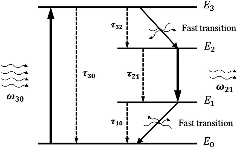
Figure 1.Simplified model of electron interaction with photons in an active medium with a two-electron, four-energy-level atomic system.
Electron transitions between energy levels and take place at a quite fast pace, and the accompanying emissions have random phases. As a result, the average radiation of electron transition between these two energy levels becomes zero as the number of transitions increases. Electron transitions between and have a similar treatment. However, and transitions are relatively slower and the resulting emissions can be coherent to an imposed electromagnetic wave.
Before any excitation, the valence electrons of the active atoms or molecules occupy two lower energy levels, and . Since two valence electrons of each active molecule cannot occupy the same energy levels, the population of these levels is almost equal before the excitation. On the other hand, due to small probability of electron transition to higher energy levels [27], there is a small population of electrons at and . Applying an electric field with appropriate frequency and polarization pumps the electrons of to ; the electrons store the energy while they are at and .
The electron interaction with the electric field obeys the Bloch relation, which results in the following governing equation for the polarization density in the medium [28]:
Here, is the polarization density between level and level ; , , and are the corresponding deshaping factor, angular frequency, and electron density adjustment factor; is the electron population density at energy level ; and is the electric field.
The electron population density at each level changes over time due to non-radiative decays and radiative emissions. The population density is governed by the Pauli exclusion principle and the following coupled electron density rate equations:
In this set of equations, is the electron average decay time between levels and ; is Planck’s constant. These equations, alongside the Maxwell equations, are discretized by the FDTD method to analyze the electromagnetic problem of the active medium in the time domain [29]. The FDTD code is modified to model dispersive media by converting the optical index in frequency domain to a summation of complex-conjugate pole–residue pairs.
3. OSCILLATOR DESIGN
Here, an optical nano-oscillator is devised based on a nonlinear active material which receives feedback from a plasmonic resonator. A plasmonic dimer provides a cavity with a high quality factor at the gap, assuming the gap is filled by the active material described in Section 2. The dimer helps the electric field energy with specific frequency and polarization to be stored in the active medium. However, the main functionality of the nano-plasmonic dimer is to capture the released energy of the active medium for a longer time in the resonator in order to assess long-last oscillations with smooth amplitude.
The dimer, which is shown in Fig. 2(a), consists of two identical metallic cylinders placed coaxially with a small gap in between filled by a semiconductor with active characteristics. An external electric field with a polarization parallel to the dimer axis excites dipoles in each cylinder, which confines the electric field around their poles.

Figure 2.Plasmonic nano-oscillator. (a) Geometry and excitation illustration. (b) Electric field enhancement of the plasmonic dimer at the center of its gap with undoped InP. (c) Time profile of the electric field excitation. (d) Probed electric field at the dimer gap with doped InP. (e) Electron population density normalized to the density of active molecules in InP at the center of the plasmonic dimer.
Because the two dipoles are coaxially adjacent, their bright mode can be stimulated to intensify the electric field confinement at their gap and cause a resonance [30,31]. The dimer resonance is set to , where is Planck’s constant. After excitation, distorted electrons at the higher energy levels tend to move back and occupy lower energy levels. Hence, the pumped electrons to mostly move to and level becomes fully populated by the electron transitions from , while electron transitions between and are relatively slower.
Here, the intensity and duration of the electric field pump are set so that electron population inversion between and does not happen and the system remains in thermal equilibrium. Based on the Fermi–Dirac relation below [27], a very small portion of the population remains in or moves to :
In Eq. (7), indicates average for the variable inside, is a constant which depends on the source of valence electrons (e.g., for donor impurities in semiconductors), is Boltzmann constant, and is temperature in Kelvin scale. An oscillating field in the high-quality-factor resonator can excite the electrons of to move back to ground state and release their energy by radiation. At the same time, refills lost electrons of and this process continues to settlement of the electric field inside the plasmonic resonator. Since the active medium overlaps the eigenmode hotspot of surface plasmons spatially and spectrally, the feedback from the resonator enhances constructive electron emission and dampens incoherent electron radiations. As a result, electron emissions become coherent with surface plasmons in this system and compensate a portion of lost energy in the resonator. Consequently, an electric field of frequency oscillates for a longer time in the resonator.
An FDTD-based commercial solver of Maxwell’s equations is employed to analyze this model numerically [29]. The dimer materials and dimensions are as follows: cylinders metal has Drude properties of gold [32] with plasma frequency of 2068 THz and damping constant of 1 THz. The length of each cylinder is 135 nm and the diameter is 20 nm; the gap between them is 20 nm and is filled with indium phosphate (InP), with optical index extracted from experiment [33]. This structure is embedded in glass with dispersionless optical index of 1.5. The intrinsic electric field enhancement of the plasmonic dimer in the gap center point is shown in Fig. 2(b) for undoped InP. The maximum quality factor of the resonator is around 18, which shows that the dissipated power of the resonator in each cycle of incident wave is a decent fraction of the oscillating energy inside it.
Then, InP is doped with Sn n-type impurity so that it has valence electron density of with and . Damping coefficient for the and transitions is 1 THz and decay time for both is 0.3 ns. The non-radiating transition between and takes places with somewhat faster decay lifetime of 0.1 ps. The performance of the described nano-plasmonic oscillator when it is excited by a plane wave with a Gaussian temporal profile is shown in Figs. 2(c)–2(e); the excitation pulse amplitude is , the half-power span of the pulse is 40 fs, and the modulation frequency is .
As Fig. 2(d) suggests, after the excitation pulse disappears, electric field inside the cavity oscillates with a relatively smaller amplitude but for a longer time. Since the cavity is lossy, the oscillation cannot last for such a long time in the absence of the active medium. However, after doping, InP turns to an active material and absorbs the pump energy, then releases it with slower pace to drive this long-last oscillation inside the cavity. Figure 2(e) shows the electron population density of each level over time, normalized by the population density of the active molecules doped to InP. After the pulse disappears, the majority of pumped electrons to migrate to . This transition is faster at the beginning but, as the number of electrons increases in , the transition slows down. The cavity dampens electron transition from to due to its low quality factor at . Nonetheless, the cavity has a good quality factor at and, based on Eq. (7), there is a small population of electrons at this energy level. As a result, any electric field of frequency inside the resonator cavity may cause electrons to release a photon with and move to . The photons compensate a portion of lost energy in the resonator, and therefore the quality of plasmon oscillation increases. However, the energy is not strong enough to overcome the loss and cause lasing. Consequently, the amplitude of the oscillation decreases and so the amount of released photons, which depends on the intensity of the electric field inside the material, decreases over the course of time. Therefore this system can be considered as an amplitude-mediated nano-optical oscillator [34].
4. CHIMERA STATES DEMONSTRATION
Here, disc arrays of identical oscillators are used to demonstrate the chimera states in a nano-resonator array system. We demonstrate the concurrent incoherent and coherent oscillation among the identical oscillators. A symmetric array is formed using the oscillators discussed in the previous section. The dimers are arranged vertically over the perimeter of a horizontal circle, equally apart from each other. A schematic illustration of the array is demonstrated in Fig. 3(a) for eight oscillators. Due to the symmetry of the system, all the members have identical resonance frequency.
Figure 3.Array schematic and an example of full coherency in the oscillators. (a) Geometry of the array and the direction of incident plane wave electric field pulse (sketched not to the real scale). (b) Probed electric field at the center of oscillator 1, where the radius of the array . Inset shows the electric field at the center of all the oscillators with time. (c) Oscillation amplitude variation for different oscillators over time.
The active medium is stimulated initially to push the electrons in the active medium to higher energy levels and cause population inversion. The higher-level electron populations of all the oscillators can be kept identical by exciting the array with cylindrically symmetric waves. Initial oscillations caused by the pump settle down over the course of time. We assume the array ended up with the following normalized population densities in the active medium: , , , and . Illuminating this array by additional plane wave pulse with Gaussian temporal profile causes long-last oscillation inside the array. The electric field at the center point of each member is a superposition of coupled electric fields from all oscillators. This field is dominated by its vertical component, and therefore the phase of each oscillator can be written as where is coupled electric field of the -th oscillator with the center point of -th modulated by the carrier. The main portion of comes from self-induced electric field while a complex coupling coefficient , which is a function of distance, relates to . After the self-induced electric field, closer neighbors have stronger contribution to because the coupling decreases rapidly with distance. In the closely packed system in which all the oscillators have strong coupling to the neighbors, oscillators tie to a common phase and oscillate coherently. As an example, the temporal response of this array to a pulse with amplitude of 1 V/m, span of 40 fs, and modulation by 100 THz is depicted in Figs. 3(c) and 3(d) when the array radius .
Figure 3(b) depicts the probed electric field at the center of oscillator 1 as an example of the array reaction to the incident pulse turbulence. The inset figure shows the oscillation after 4000 ns. All the oscillators have equal amplitude and negligible phase difference. The amplitude change over time is shown in Fig. 3(c). Right after applying the pulse, there are transient responses in the array which disappear over time. As the transient response diminishes, the oscillation amplitude decreases smoothly. In this step, the oscillation amplitude of the members barely degrades from the average of the array. In order to compare the oscillations, the phase of the electric field at the probe is sampled by
In this equation, represents phase, is sampling time, and is sampling iteration. The equation helps study the variation in the phase of oscillators. The sampled phases of oscillators in Fig. 3 alongside the sampled phase of similar geometries with , 70, and 140 nm are plotted in Fig. 4.
Figure 4.Sampled amplitude and phase of oscillator electric fields at their gap for different array geometries with eight oscillators and different disc radii: (a), (b) , (c), (d) , (e), (f) , and (g), (h) .
Figures 4(a) and 4(b) show the sampled amplitude and phase of oscillators for correspondingly. In this case, the oscillators are coherent because all of them keep a common phase over time. Although the sampled phase in Fig. 4(b) shows a slight phase variation over time, all the oscillators follow that change and stay synchronized. As the distance (d) between the oscillators increases, the coupling decreases by [35] because the dimer dimensions are comparable to the distance to the neighbor dimers. In this condition, the interparticle coupling is governed mainly by Coulombic forces between the localized surface plasmons.
For the case, the coupling is strong enough to tie some of the oscillators in coherency. Due to the symmetry of geometry and excitation, members 3 and 7 of the array are synchronized together and make a coherency domain. This means the oscillator phase difference does not change over a period of time which is quite larger than the oscillation period. It is noteworthy that amplitude of oscillation decays steadily over time for this group. The amplitudes of other array members are higher than the first group in average, but they drop below the first group periodically. These dips in amplitude cause abrupt variations of oscillation phase and lead to bursts of desynchronizations.
The oscillators return back to coherency after the bursts and synchronize again after almost 180° of phase change. This pattern repeats over time almost every 2000 ns. However, the second group remains synchronized most of the time. As a result, the array in its current form is divided into two synchronized populations in which one of the populations possesses quasi-periodic bursts of desynchronization. Consequently, the state is an indication of chimera oscillations in this nano-particle system.
The states are not sensitive to the direction excitation pulse. They will reappear with the same period and similar pattern, but some oscillators may switch their initial chimera heads. The oscillator which starts escaping is always the same in this system: oscillator 1, which is the closest one to the excitation source. This member starts oscillating in phase with its neighbors; since this is a system dark mode with higher energy level, the oscillations tend to transit to bright modes with lower energy level and higher stability. In bright mode, neighbor resonators oscillate 180° out of phase. Furthermore, oscillators that escape from synchronization return back to their domain shortly after the burst of desynchronization.
As the distance between the oscillators further increases, their coupling further reduces. For the case [Figs. 4(e) and 4(f)], amplitude dips are weaker so phase pattern does not have abrupt transitions. Furthermore, the synchronization is weaker and the array becomes a three-head chimera due to three distinct phase patterns among the oscillators. Interestingly, two groups of closed neighbors stay synchronized, and any escape by a member is compensated by the other members in the group to keep synchronization. For instance, oscillators 4 and 6 escape from a common head with 5, but 5 tracks their changes at and 4800 ns. As a result, the coupling strength directly affects the chimera head number and the strength of phase escape from synchronization. Figures 4(g) and 4(h) show the array amplitude and phase for ; in this case, the coupling is weak such that oscillators seem to oscillate freely. As a result, their sampled phase diagram is smoother. Some members are synchronized and keep track of phase escapes of the other members from their head chimera. If the coupling among the members becomes negligible for very long distances, they oscillate freely but coherently. However, this coherence is more sensitive to noise compared to the coherence of strongly coupled oscillators.
The simulation is repeated for an array with 16 oscillators, but the distance among neighboring oscillators is kept the same as the previous example. The results are depicted in Fig. 5. As expected, for the case of very close oscillators and strong coupling [Fig. 5(b), ], the phase difference among oscillators remains almost constant over the course of time, with slight occasional variations for some members. In this case, oscillators are synchronized and no phase escape takes place. However, for [Fig. 5(b)], in which the coupling among oscillators is not as strong as in the first case, the oscillators escape from coherency but synchronize back. Comparing the corresponding configuration of eight oscillators, here the period of escapes is twice as long. As the distance among oscillators increases, they start to oscillate much more freely [Figs. 5(c) and 5(d)]. As mentioned, the synchronization for these cases is very sensitive to external turbulence and noise.
Figure 5.Sampled phase of oscillator electric fields at their gap for different array geometries with 16 oscillators and different disc radii: (a) , (b) , (c) , and (d) . These radii are selected to keep the inter-oscillator distances the same as those of the corresponding array in Fig. 4.
In comparing these eight cases, it can be concluded that synchronization tendency among the oscillator decreases with increasing distance. The chimera states merge where the coupling between the oscillators is big enough to keep some of the oscillators coherent but not strong enough to force all of them to synchronize together. The time period of chimera escapes also depends on the number of oscillators. One can expect to observe similar states in extended systems with larger arrays of oscillators. Even though the period of drifting increases in the extended systems, they are always accompanied by coherent domains; as a result, their combination can be called a chimera.
5. CONCLUSION
In summary, we demonstrate chimera states for plasmonic nano-resonators. A surface-plasmon-based nano-optical oscillator is modeled using numerical implementation of Maxwell’s equations coupled with the electron-rate equations of the active medium located in the plasmon hotspot. It is shown that the oscillator has a stable oscillation phase and amplitude over time. Chimera states are demonstrated and studied using this oscillator system in a disc array of closely and symmetrically coupled oscillators. It was found that the synchronization and rate of escape from synchronization depend on the distance of the oscillators from each other. The chimera heads merge when the coupling between the oscillators is big enough to keep some of the oscillators coherent but not strong enough to force all of them to synchronize together. These states are insensitive to the direction of excitation turbulence, and the period of escape depends on the number of oscillators in the array.
References
[1] Y. Kuramoto, D. Battogtokh. Coexistence of coherence and incoherence in nonlocally coupled phase oscillators(2002).
[2] O. E. Omel’chenko. Coherence-incoherence patterns in a ring of non-locally coupled phase oscillators. Nonlinearity, 26, 2469-2498(2013).
[3] D. M. Abrams, S. H. Strogatz. Chimera states for coupled oscillators. Phys. Rev Lett., 93, 174102(2004).
[4] N. Verschueren, U. Bortolozzo, M. G. Clerc, S. Residori. Spatiotemporal chaotic localized state in liquid crystal light valve experiments with optical feedback. Phys. Rev. Lett., 110, 104101(2013).
[5] G. C. Sethia, A. Sen, F. M. Atay. Clustered chimera states in delay-coupled oscillator systems. Phys. Rev. Lett., 100, 144102(2008).
[6] E. Omel’chenko, Y. L. Maistrenko, P. A. Tass. Chimera states: the natural link between coherence and incoherence. Phys. Rev. Lett., 100, 044105(2008).
[7] I. Omelchenko, Y. Maistrenko, P. Hövel, E. Schöll. Loss of coherence in dynamical networks: spatial chaos and chimera states. Phys. Rev. Lett., 106, 234102(2011).
[8] S. Nkomo, M. R. Tinsley, K. Showalter. Chimera states in populations of nonlocally coupled chemical oscillators. Phys. Rev. Lett., 110, 244102(2013).
[9] M. Wolfrum, E. Omel’chenko. Chimera states are chaotic transients. Phys. Rev. E, 84, 015201(2011).
[10] A. M. Hagerstrom, T. E. Murphy, R. Roy, P. Hövel, I. Omelchenko, E. Schöll. Experimental observation of chimeras in coupled-map lattices. Nat. Phys., 8, 658-661(2012).
[11] M. R. Tinsley, S. Nkomo, K. Showalter. Chimera and phase-cluster states in populations of coupled chemical oscillators. Nat. Phys., 8, 662-665(2012).
[12] L. Larger, B. Penkovsky, Y. Maistrenko. Virtual chimera states for delayed-feedback systems. Phys. Rev. Lett., 111, 054103(2013).
[13] E. A. Martens, S. Thutupalli, A. Fourrière, O. Hallatschek. Chimera states in mechanical oscillator networks. Proc. Natl Acad. Sci. U.S.A., 110, 10563-10567(2013).
[14] J. Wojewoda, K. Czolczynski, Y. Maistrenko, T. Kapitaniak. The smallest chimera state for coupled pendula. Sci. Rep., 6, 34329(2016).
[15] L. Larger, B. Penkovsky, Y. Maistrenko. Laser chimeras as a paradigm for multistable patterns in complex systems. Nat. Commun., 6, 7752(2015).
[16] J. Shena, J. Hizanidis, V. Kovanis, G. P. Tsironis. Turbulent chimeras in large semiconductor laser arrays. Sci. Rep., 7, 42116(2017).
[17] M. G. Clerc, M. A. Ferré, S. Coulibaly, R. G. Rojas, M. Tlidi. Chimera-like states in an array of coupled-waveguide resonators. Opt. Lett., 42, 2906-2909(2017).
[18] E. Tognoli, J. S. Kelso. The metastable brain. Neuron, 81, 35-48(2014).
[19] D. M. Abrams, R. Mirollo, S. H. Strogatz, D. A. Wiley. Solvable model for chimera states of coupled oscillators. Phys. Rev. Lett., 101, 084103(2008).
[20] M. J. Panaggio, D. M. Abrams. Chimera states: coexistence of coherence and incoherence in networks of coupled oscillators. Nonlinearity, 28, R67-R87(2015).
[21] D. J. Bergman, M. I. Stockman. Surface plasmon amplification by stimulated emission of radiation: quantum generation of coherent surface plasmons in nanosystems. Phys. Rev. Lett., 90, 027402(2003).
[22] N. I. Zheludev, S. Prosvirnin, N. Papasimakis, V. Fedotov. Lasing spaser. Nat. Photonics, 2, 351-354(2008).
[23] M. I. Stockman. Spasers explained. Nat. Photonics, 2, 327-329(2008).
[24] C. M. Soukoulis, S. Linden, M. Wegener. Negative refractive index at optical wavelengths. Science, 315, 47-49(2007).
[25] E. Plum, V. Fedotov, P. Kuo, D. Tsai, N. Zheludev. Towards the lasing spaser: controlling metamaterial optical response with semiconductor quantum dots. Opt. Express, 17, 8548-8551(2009).
[26] S. Xiao, V. P. Drachev, A. V. Kildishev, X. Ni, U. K. Chettiar, H.-K. Yuan, V. M. Shalaev. Loss-free and active optical negative-index metamaterials. Nature, 466, 735-738(2010).
[27] F. Reif. Fundamentals of Statistical and Thermal Physics(2009).
[28] S.-H. Chang, A. Taflove. Finite-difference time-domain model of lasing action in a four-level two-electron atomic system. Opt. Express, 12, 3827-3833(2004).
[29] . FDTD Solutions(2016).
[30] P. Nordlander, C. Oubre, E. Prodan, K. Li, M. Stockman. Plasmon hybridization in nanoparticle dimers. Nano Lett., 4, 899-903(2004).
[31] B. Willingham, D. Brandl, P. Nordlander. Plasmon hybridization in nanorod dimers. Appl. Phys. B, 93, 209-216(2008).
[32] M. G. Blaber, M. D. Arnold, M. J. Ford. Search for the ideal plasmonic nanoshell: the effects of surface scattering and alternatives to gold and silver. J. Phys. Chem. C, 113, 3041-3045(2009).
[33] E. D. Palik. Handbook of Optical Constants of Solids, 3(1998).
[34] G. C. Sethia, A. Sen. Chimera states: the existence criteria revisited. Phys. Rev. Lett., 112, 144101(2014).
[35] P. K. Jain, S. Eustis, M. A. El-Sayed. Plasmon coupling in nanorod assemblies: optical absorption, discrete dipole approximation simulation, and exciton-coupling model. J. Phys. Chem. B, 110, 18243-18253(2006).


