• Chinese Optics Letters
  • Vol. 20, Issue 4, 042501 (2022)
Zengyi Xu1、2, Wenqing Niu1, Jianyang Shi1, and Nan Chi1、*
Author Affiliations
  • 1Key Laboratory for Information Science of Electromagnetic Waves (MoE), Department of Communication Science and Engineering, Fudan University, Shanghai 200433, China
  • 2Peng Cheng Laboratory, Shenzhen 518055, China
  • show less
    DOI: 10.3788/COL202220.042501 Cite this Article Set citation alerts
    Zengyi Xu, Wenqing Niu, Jianyang Shi, Nan Chi. Nonlinear coded nonuniform superposition QAM by trellis-coding for MISO system in visible light communication[J]. Chinese Optics Letters, 2022, 20(4): 042501 Copy Citation Text show less
    Principle of NCNS-QAM algorithm. A 36-QAM is implemented by superposing two independent PAM6 signals generated by the original PAM4 ones. The in-phase and quadrature signals are later demodulated as in the regular QAM scheme, resulting in two independent PAM6 data. After the nonlinear decoding step, the original PAM4 data is recovered.
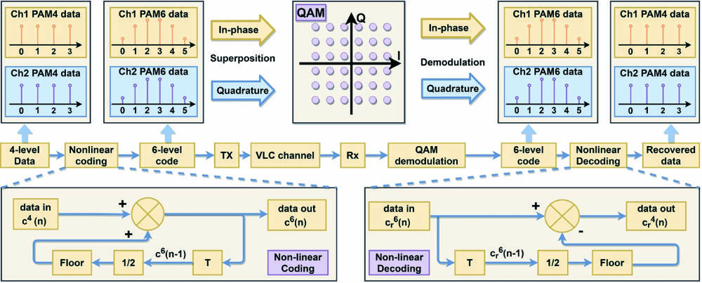
    Fig. 1. Principle of NCNS-QAM algorithm. A 36-QAM is implemented by superposing two independent PAM6 signals generated by the original PAM4 ones. The in-phase and quadrature signals are later demodulated as in the regular QAM scheme, resulting in two independent PAM6 data. After the nonlinear decoding step, the original PAM4 data is recovered.
    Setup for the NCNS-QAM experiment. Two independent LED channels transmit optical signals, which are received by a single PIN detector. The original four-level PAM4 signal experiences nonlinear coding (PAM4 to PAM6 mapping), upsampling, roll-off filtering, before up-conversion. In up-conversion, the two channels are mixed with orthogonal carriers and thus form a QAM signal at the receiver. After the signal is received, it undergoes down-conversion (as in QAM demodulation), roll-off filtering, joint LMS equalization, and nonlinear decoding. TX, transmitter; RX, receiver; Eq., hardware equalizer; EA, electrical amplifier; OSC, oscilloscope; PIN, p-i-n photo detector.
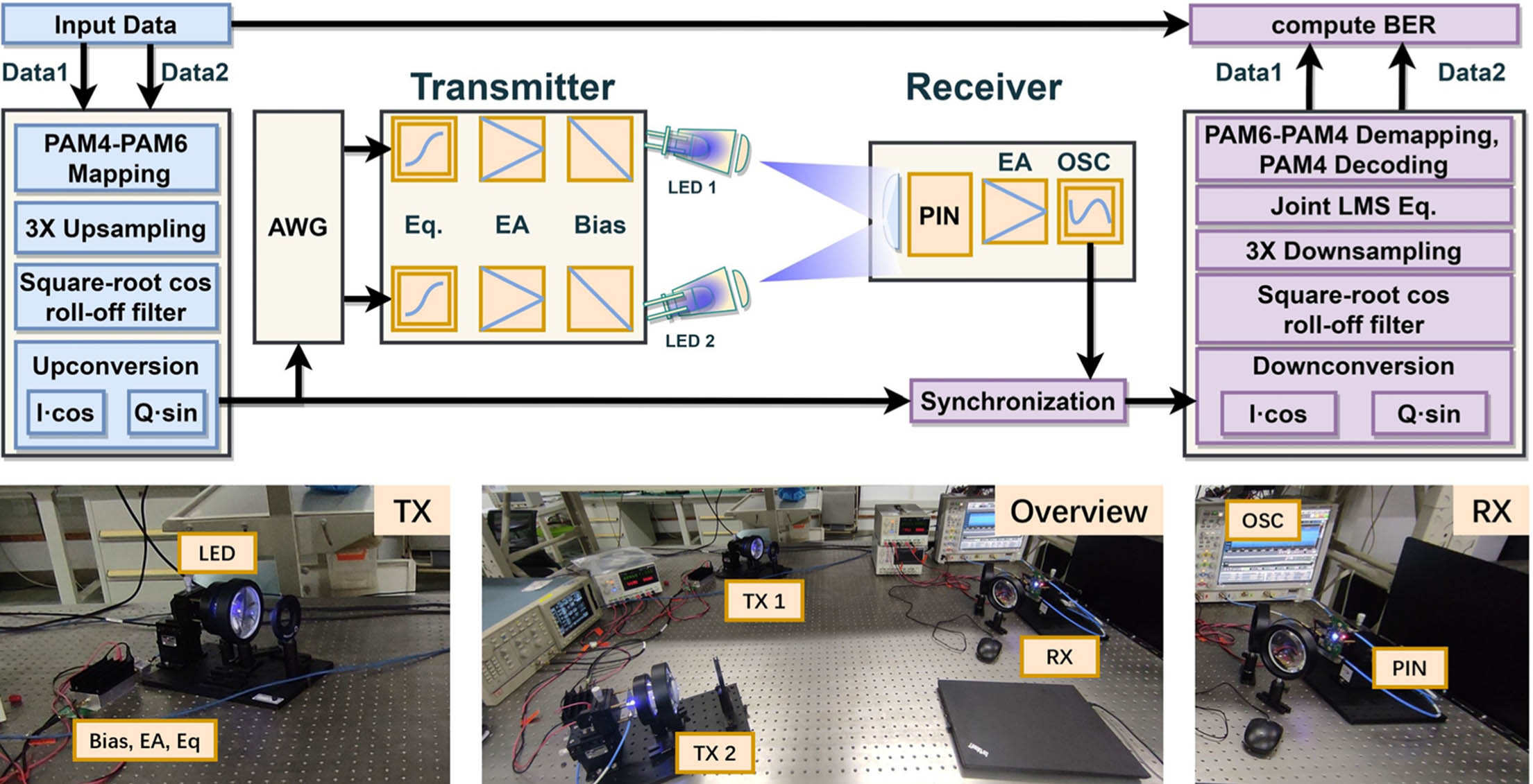
    Fig. 2. Setup for the NCNS-QAM experiment. Two independent LED channels transmit optical signals, which are received by a single PIN detector. The original four-level PAM4 signal experiences nonlinear coding (PAM4 to PAM6 mapping), upsampling, roll-off filtering, before up-conversion. In up-conversion, the two channels are mixed with orthogonal carriers and thus form a QAM signal at the receiver. After the signal is received, it undergoes down-conversion (as in QAM demodulation), roll-off filtering, joint LMS equalization, and nonlinear decoding. TX, transmitter; RX, receiver; Eq., hardware equalizer; EA, electrical amplifier; OSC, oscilloscope; PIN, p-i-n photo detector.
    BER versus Vpp for both PAM4 and NCNS. The A group insets are the constellation diagrams at 400 mV: (i) PAM4, (ii) NCNS, and (iii) the four-level decoded result from NCNS. The B group insets are the constellation diagrams at 600 mV: (iv) PAM4, (v) NCNS, and (vi) the four-level decoded result from NCNS.
    Fig. 3. BER versus Vpp for both PAM4 and NCNS. The A group insets are the constellation diagrams at 400 mV: (i) PAM4, (ii) NCNS, and (iii) the four-level decoded result from NCNS. The B group insets are the constellation diagrams at 600 mV: (iv) PAM4, (v) NCNS, and (vi) the four-level decoded result from NCNS.
    First and second columns are the spectra of TX and RX signals in both PAM4 (orange) and NCNS (blue). (a), (e) Vpp = 400 mV and (b), (f) Vpp = 600 mV. The third column is the probability density of RX symbol under 600 mV in (c) PAM4 and (g) NCNS. The last column is the probability distribution of each symbol in superposed QAM by (d) PAM4 or (h) NCNS when transmitting the same length of original data.
    Fig. 4. First and second columns are the spectra of TX and RX signals in both PAM4 (orange) and NCNS (blue). (a), (e) Vpp = 400 mV and (b), (f) Vpp = 600 mV. The third column is the probability density of RX symbol under 600 mV in (c) PAM4 and (g) NCNS. The last column is the probability distribution of each symbol in superposed QAM by (d) PAM4 or (h) NCNS when transmitting the same length of original data.
    Joint LMS equalizer tap weights in channel 1. (a) shows the tap weights w11 for compensating inter-symbol interference (ISI) from channel 1 itself, and (b) shows the tap weights w12 for compensating inter-channel interference (ICI) from channel 2. The two channels are assumed symmetrical in ISI and ICI. The data are collected at Vpp = 600 mV.
    Fig. 5. Joint LMS equalizer tap weights in channel 1. (a) shows the tap weights w11 for compensating inter-symbol interference (ISI) from channel 1 itself, and (b) shows the tap weights w12 for compensating inter-channel interference (ICI) from channel 2. The two channels are assumed symmetrical in ISI and ICI. The data are collected at Vpp = 600 mV.
    Comparison in averaged BER of the two channels between the (a) PAM4 and (b) NCNS. The area enclosed by the dash line represents the usable area with BER lower than the threshold for 7% FEC. NCNS has 0.24 V2 dynamic range, which is 33% larger than that of PAM4 (0.18 V2).
    Fig. 6. Comparison in averaged BER of the two channels between the (a) PAM4 and (b) NCNS. The area enclosed by the dash line represents the usable area with BER lower than the threshold for 7% FEC. NCNS has 0.24 V2 dynamic range, which is 33% larger than that of PAM4 (0.18 V2).
    Channel/CodeW0RMS ISIRMS ICIISI/W0ICI/W0
    CH1/NCNS0.9560.07550.1457.90%15.2%
    CH2/NCNS0.9210.08290.1379.00%14.9%
    CH1/PAM40.9810.11200.19511.4%19.8%
    CH2/PAM40.9840.11200.20611.3%20.9%
    Table 1. ISI and ICI Measured by LMS Tap Weights
    Zengyi Xu, Wenqing Niu, Jianyang Shi, Nan Chi. Nonlinear coded nonuniform superposition QAM by trellis-coding for MISO system in visible light communication[J]. Chinese Optics Letters, 2022, 20(4): 042501
    Download Citation