
Zengyi Xu, Wenqing Niu, Jianyang Shi, Nan Chi. Nonlinear coded nonuniform superposition QAM by trellis-coding for MISO system in visible light communication[J]. Chinese Optics Letters, 2022, 20(4): 042501
- Chinese Optics Letters
- Vol. 20, Issue 4, 042501 (2022)
Abstract
Keywords
1. Introduction
The visible light communication (VLC) system, which utilizes the 400–800 THz spectrum, is predicted as a promising technique in the upcoming 6G communication due to its desired characteristics such as high confidentiality, rich spectrum resources, being free from license and patent, low electromagnetic pollution, and other advantages[
The multi-input multi-output (MIMO) system has proven its importance in the past 4G and current 5G networks[
This situation encourages the combination of VLC with MIMO/MISO, where LEDs and photo detector (PD) arrays resemble the antennas in their RF counterparts. The bandwidth limitation of LEDs can be compensated by increasing the number of parallel transmitters[
Sign up for Chinese Optics Letters TOC. Get the latest issue of Chinese Optics Letters delivered right to you!Sign up now
Nonlinear coding is an effective measure to alleviate the negative influence from nonlinearity, which is able to modify the signal in either the time domain or frequency domain (or both), in the meantime, as some of them apply trellis-coded modulation (TCM) that adds correlation between adjacent symbols[
However, the previous work in Refs. [15,16] separates the transmission of two different channels using two independent receivers. With scalar superposed coded modulation (Scalar-SCM), it could form a superposed quadrature amplitude modulation (QAM) signal at the receiver, which follows a similar demodulation purpose but has an unevenly distributed constellation point. Instead of using unbalanced coding schemes for different channels[
A joint least mean square (LMS) (MIMO LMS) software equalizer[
2. Methodology
Applying the algorithm shown in Fig. 1, which is described by Yamamoto et al. in Refs. [15,16], two independent six-level codes are obtained from two uniformly distributed four-level signals . It leaves a clear path in the trellis diagram. The distribution of can be written in the following form:
![]()
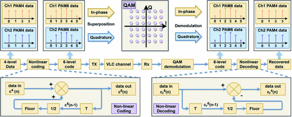
Figure 1.Principle of NCNS-QAM algorithm. A 36-QAM is implemented by superposing two independent PAM6 signals generated by the original PAM4 ones. The in-phase and quadrature signals are later demodulated as in the regular QAM scheme, resulting in two independent PAM6 data. After the nonlinear decoding step, the original PAM4 data is recovered.
To implement the vector symbol in an MISO system, firstly, the positive integers in are shifted and scaled into as pulse amplitude modulation (PAM) requires. It needs upsampling and a roll-off filtering process to achieve pulse shaping:
Next, the filtered samples are mixed with one of the two orthogonal carriers, either or , as the equation describes:
The expression for the two PAM signals reminds us of the description of the in-phase and quadrature component in QAM. One pair of superposed orthogonal signals can be regarded as a single complexed-valued QAM symbol:
To decode the 36-QAM signals, the process is similar to that in QAM:
The result experiences down sampling and another round of roll-off filtering with the same parameter as in Eq. (3) to obtain the recovered data and :
The recovered data is later processed using maximum likelihood decision (or minimum Euclidian distance). The result is the six-level codes and . By applying the nonlinear decoding algorithm illustrated in Fig. 1, the four-level recovered data would be obtained.
This precoding technique has a linear time complexity to the length of the original four-level code and a fixed space complexity O(1) as the memory only stores the last six-level code and the current four-level one to encode a new six-level one.
The experiment setup is illustrated in Fig. 2. The input data is firstly encoded into PAM4 and afterwards mapped into PAM6. The signal is upsampled by three times and experiences a square-root cosine roll-off filter to control its spread in time domain. The up-conversion step divides the signal into in-phase and quadrature components and feeds them into the two independent channels in the arbitrary waveform generator (AWG). Simultaneously, an offline file is stored for synchronization. Next, the signal is equalized, amplified, and biased for the transmission using LEDs. The received signal is sampled from the oscilloscope and experiences the inverse process it has been through in the transmitter. An extra step, LMS software equalization, is added to compensate the linear loss in the channel. To improve the BER performance, the LMS algorithm is applied at the receiver. Its taps weights provide evidence to compare the performance of PAM4 and NCNS. Finally, by comparing the decoded information to the original data saved in an offline file, the BER is computed and used for evaluation of the communication quality.
![]()
Figure 2.Setup for the NCNS-QAM experiment. Two independent LED channels transmit optical signals, which are received by a single PIN detector. The original four-level PAM4 signal experiences nonlinear coding (PAM4 to PAM6 mapping), upsampling, roll-off filtering, before up-conversion. In up-conversion, the two channels are mixed with orthogonal carriers and thus form a QAM signal at the receiver. After the signal is received, it undergoes down-conversion (as in QAM demodulation), roll-off filtering, joint LMS equalization, and nonlinear decoding. TX, transmitter; RX, receiver; Eq., hardware equalizer; EA, electrical amplifier; OSC, oscilloscope; PIN, p-i-n photo detector.
The MISO system used in this experiment is built using two LEDs and one PIN photodiode. The LED used is developed by Nanchang University, featuring 450 nm peak wavelength and maximum 2.25 Gb/s data rate. The PIN is Hamamatsu S10784, of which the usable wavelength covers 400–1000 nm. The oscilloscope is Agilent Technologies MSO9254A, and the AWG is SONY Tektronix AWG520. The bias tee and amplifier used in this experiment are Mini-Circuits ZFBT-4R2GW-FT and ZHL-6 A-S+.
3. Result
This experiment tests both the PAM4 and NCNS modulation schemes, setting the bias current at 35 mA. The AWG generates the transmitted signal at 900 MSa/s with three times upsampling. The data rate in this experiment is therefore 1200 Mb/s. To demonstrate and compare the strength and weakness of the two modulation schemes, this experiment samples the BER of both at varying from 200 mV to 1000 mV, which includes both the low signal-to-noise case and the high (also high nonlinearity) case.
The samples constitute two five-by-five grids, whose diagonal line shows the case where the two channels are balanced with equal (as the baseline of analysis). The result is plotted in Fig. 3. The line chart in Fig. 3 shows the case where both channels transmit signals with equal . Although, in the low power case below 600 mV , NCNS is outperformed by PAM4, the maximum usable of NCNS is about 100 mV (or 16%) higher than that of PAM4. The insets give more details about this phenomenon. In each group, the three diagrams from left to right indicate the signal quality of PAM4, NCNS, and the result from NCNS decoding, intuitively showing the effect of NCNS.
![]()
Figure 3.BER versus Vpp for both PAM4 and NCNS. The A group insets are the constellation diagrams at 400 mV: (i) PAM4, (ii) NCNS, and (iii) the four-level decoded result from NCNS. The B group insets are the constellation diagrams at 600 mV: (iv) PAM4, (v) NCNS, and (vi) the four-level decoded result from NCNS.
In the 400 mV case, because the distance between the constellation points in NCNS is less than that in PAM4, and SNR is comparatively low, the constellation points in NCNS are less desirable compared with those in PAM4, so are the constellation points after nonlinear decoding in NCNS. However, the situation is flipped in the 600 mV case, where the difference in BER is the most significant. The nonlinearity remarkably distorts the PAM4 constellation points, especially the peripheral ones. For example, the constellation points at the four corners are so severely distorted that they lose their round shape.
By contrast, NCNS successfully limits the deformation of constellation points. Meanwhile, the decoded result also demonstrates more concentrated constellation points compared with PAM4. The constellation diagram in Fig. 3 gives an explanation to the improvement in BER by NCNS, which is due to the nonuniform distribution, and NCNS sends more signals with lower power transmitted and thus avoids the nonlinear region. Although NCNS performs less attractively when the VLC system is SNR restricted, when the nonlinearity replaces noise and becomes the main cause of BER, NCNS performs better than PAM4. This conclusion can be solidified using Fig. 4.
![]()
Figure 4.First and second columns are the spectra of TX and RX signals in both PAM4 (orange) and NCNS (blue). (a), (e) Vpp = 400 mV and (b), (f) Vpp = 600 mV. The third column is the probability density of RX symbol under 600 mV in (c) PAM4 and (g) NCNS. The last column is the probability distribution of each symbol in superposed QAM by (d) PAM4 or (h) NCNS when transmitting the same length of original data.
To provide detailed information, the power spectra at 400 mV and 600 mV are plotted in Fig. 4. The histogram of symbols from single channel and after the superposed QAM is also plotted in Fig. 4. Compared with the PAM4 spectrum in Fig. 4(a), the spectrum in Fig. 4(e) is less distinguishable from the background noise. However, at 600 mV, with the SNR increased in both spectra in Figs. 4(b) and 4(f), the signal bands are clearly distinguishable from background noise. Figures 4(c) and 4(g) illustrate the distribution of the received symbols, where PAM4 is mainly uniform, while NCNS is otherwise. The last pair of diagrams in Figs. 4(d) and 4(h) shows the distribution of the superposed QAM signal by PAM4 and by NCNS, which also demonstrates their difference in symbol probability. Furthermore, in Fig. 4(c), the histogram suggests that peaks are overlapping except for the central two, while in Fig. 4(g) this phenomenon is less severe. It means that more received symbols are distributed closer to the expected value in NCNS than in PAM4, which means fewer symbols are wrongly decided as it deviates from its original value and falls into the decision region for other symbols.
Assuming the averaged amplitude on each tap of the joint LMS equalizer is the same, the tap weight indirectly gives information about the intensity of ISI and ICI. The result is plotted in Fig. 5, where Fig. 5(a) gives the tap weights for ISI, and Fig. 5(b) shows tap weights for ICI. The RMS value of the tap weights is calculated and recorded in Table 1. To further explore the details, the RMS value and the ratio of the center tap weight to the RMS value of the others are calculated and listed in the Table 1, where both channels in NCNS and PAM4 are included. NCNS presents a lower ratio in all of the four cases.
As the LMS equalizer outputs the weighted sum of all of the taps, the squared weight can be interpreted as the influence in signal power from the adjacent symbols, assuming the averaged value from each tap is the same. The central tap (tap 6) in Fig. 5(a) corresponds to the influence from the expected symbol, but the others are regarded as ISI and ICI. The data in Table 1 suggests that, in the NCNS case, the LMS output is dominated by the expected symbol and less affected by the adjacent one or from the other channel.
| Channel/Code | RMS ISI | RMS ICI | |||
|---|---|---|---|---|---|
| CH1/NCNS | 0.956 | 0.0755 | 0.145 | 7.90% | 15.2% |
| CH2/NCNS | 0.921 | 0.0829 | 0.137 | 9.00% | 14.9% |
| CH1/PAM4 | 0.981 | 0.1120 | 0.195 | 11.4% | 19.8% |
| CH2/PAM4 | 0.984 | 0.1120 | 0.206 | 11.3% | 20.9% |
Table 1. ISI and ICI Measured by LMS Tap Weights
Figure 6 plots two heat maps of the mean BER of the two channels. The result is generated from interpolation to the five-by-five grid of the original 25 samples using the cubic function. It gives a distinct contrast in dynamic area enclosed by the threshold BER level. The subplot of Figs. 6(a) and 6(b) shows that NCNS provides a larger dynamic range for lossless communication with 7% FEC applied, extending the boundary into the right top corner where the nonlinearity is the most severe. The gradient in the color map indicates that NCNS has a flatter BER distribution as Fig. 3 also shows. The dynamic area in NCNS is , about 33% larger than that in PAM4 (). The final result in Fig. 6 clearly demonstrates the merit of NCNS. Compared with superposed modulation using PAM4, the maximum usable range increases by 33%. This improvement means that higher signal power could be applied in the VLC system. Meanwhile, the system is more robust against fluctuating . When the bias point is the same, NCNS allows a larger jittering in but still keeps the BER under the threshold.
![]()
Figure 6.Comparison in averaged BER of the two channels between the (a) PAM4 and (b) NCNS. The area enclosed by the dash line represents the usable area with BER lower than the threshold for 7% FEC. NCNS has 0.24 V2 dynamic range, which is 33% larger than that of PAM4 (0.18 V2).
![]()
Figure 5.Joint LMS equalizer tap weights in channel 1. (a) shows the tap weights w11 for compensating inter-symbol interference (ISI) from channel 1 itself, and (b) shows the tap weights w12 for compensating inter-channel interference (ICI) from channel 2. The two channels are assumed symmetrical in ISI and ICI. The data are collected at Vpp = 600 mV.
4. Conclusion
The distribution of symbols plays a decisive role in their performance within the same , which accounts for most of the difference it presents compared with PAM4. In this experiment, NCNS precoding lowers the averaged signal power and thus increases the dynamic range significantly in high , but it sacrifices the system performance at lower . This feature is desirable in large power VLC systems, where the high power frequently causes severe nonlinearity. Apart from terrestrial VLC networks, underwater VLC (UVLC) systems would especially benefit, as the power requirement is usually higher to overcome the scattering and absorption. In the meantime, the VLC system could be more robust when jittering in is present. With NCNS and its larger dynamic range, the is less likely to cross the boundary, and thus the VLC system is more possible to control BER under the threshold. This experiment shows that NCNS-QAM could be a useful modulation scheme in the future and help the VLC system to stretch further and deeper into the unknown region.
References
[1] N. Chi, Y. Zhou, Y. Wei, F. Hu. Visible light communication in 6G: advances, challenges, and prospects. IEEE Veh. Technol. Mag., 15, 93(2020).
[2] W. Jiang, B. Han, M. A. Habibi, H. D. Schotten. The road towards 6G: a comprehensive survey. IEEE Open J. Commun. Soc., 2, 334(2021).
[3] S. Chen, J. Zhang, Y. Jin, B. Ai. Wireless powered IoE for 6G: massive access meets scalable cell-free massive MIMO. China Commun., 17, 92(2020).
[4] Y. L. Lee, D. Qin, L. C. Wang, G. H. Sim. 6G massive radio access networks: key applications, requirements and challenges. IEEE Open J. Veh. Technol., 2, 54(2021).
[5] C. Chen, W. Zhong, H. Yang, P. Du. On the performance of MIMO-NOMA-based visible light communication systems. IEEE Photonics Technol. Lett., 30, 307(2018).
[6] W. Wang, Y. Zhu, Y. Zhang, J. Zhang. An optimal power allocation for multi-LED phase-shifted-based MISO VLC systems. IEEE Photonics Technol. Lett., 27, 2391(2015).
[7] H. Ji, S. Qiao, T. Zhang. A MISO-VLC system based on LACO-OFDM and superposed constellation demodulation. 9th International Conference on Information Science and Technology, 294(2019).
[8] L. Qiao, X. Lu, S. Liang, J. Zhang, N. Chi. MISO visible light communication system utilizing hybrid post-equalizer aided pre-convergence of STBC decoding. Chin. Opt. Lett., 16, 060604(2018).
[9] C. Wang, G. Li, F. Hu, Y. Zhao, J. Jia, P. Zou, Q. Lu, J. Chen, Z. Li, N. Chi. Visible light communication for vehicle to everything beyond 1 Gb/s based on an LED car headlight and a 2 × 2 PIN array. Chin. Opt. Lett., 18, 110602(2020).
[10] X. Deng, S. Mardanikorani, Y. Wu, K. Arulandu, B. Chen, A. M. Khalid, J. M. G. Linnartz. Mitigating LED nonlinearity to enhance visible light communications. IEEE Trans. Commun., 66, 5593(2018).
[11] A. R. Calderbank, T. Lee, J. E. Mazo. Baseband trellis codes with a spectral null at zero. IEEE Trans. Inf. Theory, 34, 425(1988).
[12] K. Igarashi, T. Tsuritani, I. Morita. Polybinary shaping for highly-spectral-efficient super-Nyquist WDM QAM signals. J. Lightwave Technol., 34, 1724(2016).
[13] J. S. Park, S. B. Gelfand, M. P. Fitz. A spectral shaping nonlinear binary coded modulation with Gray-mapped QAM signals. Milcom 2010 Military Communications Conference, 2363(2010).
[14] N. Stojanovic, C. Prodaniuc, F. Karinou, Z. Qiang. 56-Gbit/s 4-D PAM-4 TCM transmission evaluation for 400-G data center applications. Optical Fiber Communications Conference and Exhibition, Th1G.6(2016).
[15] S. Yamamoto, A. Masuda, H. Taniguchi, Y. Kisaka. 92-Gbaud PAM4 transmission using spectral-shaping trellis-coded-modulation with 20-GHz bandwidth limitation. Optical Fiber Communications Conference and Exhibition, W4I.5(2019).
[16] S. Yamamoto, H. Taniguchi, A. Matsushita, M. Nakamura, S. Okamoto, Y. Kisaka. Spectral-shaping technique based on nonlinear-coded-modulation for short-reach optical transmission. J. Lightwave Technol., 38, 466(2020).
[17] F. Buchali, F. Steiner, G. Böcherer, L. Schmalen, P. Schulte, W. Idler. Rate adaptation and reach increase by probabilistically shaped 64-QAM: an experimental demonstration. J. Lightwave Technol., 34, 1599(2016).
[18] H. Xin, K. Zhang, D. Kong, Q. Zhuge, Y. Fu, S. Jia, W. Hu, H. Hu. Nonlinear Tomlinson–Harashima precoding for direct-detected double sideband PAM-4 transmission without dispersion compensation. Opt. Express, 27, 19156(2019).
[19] X. Guo, N. Chi. Superposed 32QAM constellation design for 2 × 2 spatial multiplexing MIMO VLC systems. J. Lightwave Technol., 38, 1702(2020).
[20] H. Huang, P. Shih, C. Lin, Y. Cheng, W. Liang, C. Ho, C. Wei, A. Ng’oma. 2 × 2 MIMO OFDM-RoF system employing LMS-based equalizer with I/Q imbalance compensation at 60 GHz. IEEE Photonics J., 6, 7200307(2014).

Set citation alerts for the article
Please enter your email address
© Copyright 2018-2021 | Chinese Laser Press. All Rights Reserved 沪ICP备15018463号-20