
Hanshuo Wu, Haobo Li, Yi An, Ruixian Li, Xiao Chen, Hu Xiao, Liangjin Huang, Huan Yang, Zhiping Yan, Jinyong Leng, Zhiyong Pan, Pu Zhou. Transverse mode instability mitigation in a high-power confined-doped fiber amplifier with good beam quality through seed laser control[J]. High Power Laser Science and Engineering, 2022, 10(6): 06000e44
- High Power Laser Science and Engineering
- Vol. 10, Issue 6, 06000e44 (2022)
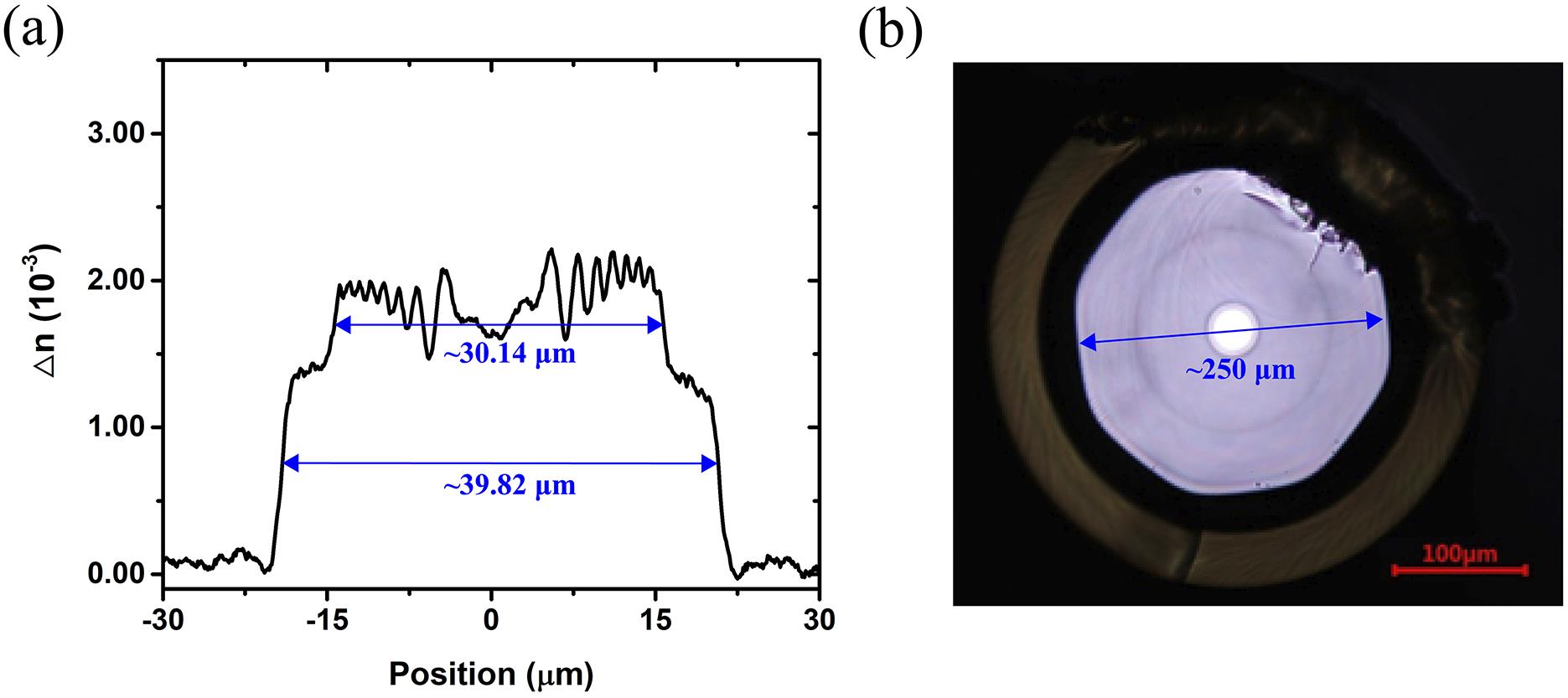
Fig. 1. (a) Refractive index profile of the fiber across the core region; (b) cross-section photograph of the confined-doped fiber.
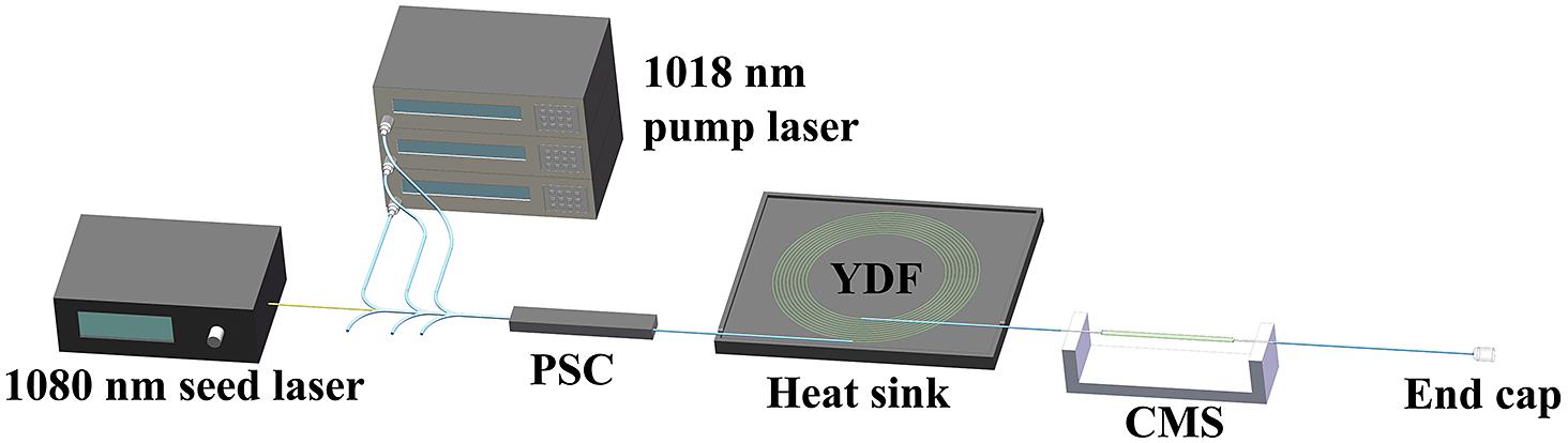
Fig. 2. Experimental schematic of the confined-doped fiber amplifier (PSC, pump and signal combiner; YDF, ytterbium-doped fiber; CMS, cladding mode stripper).
Fig. 3. (a) The output power and optical-to-optical efficiency as a function of the pump power; (b) the beam quality factor evolution as a function of the output power.
Fig. 4. The TMI threshold and extracted power as a function of seed laser power.
Fig. 5. The experimental schematic of the power controllable seed laser based on the bending loss mechanism.
Fig. 6. The experimental schematic of the S2 measurement (TFL, tunable fiber laser; FUT, fiber under test; MO, microscope objective; CCD, charge-coupled device).
Fig. 7. S2 measurement results when the bending diameter of the FUT is (a) 35 cm, (b) 20 cm, (c) 15 cm and (d) 8 cm.
Fig. 8. Extracted power at different seed laser powers.
Fig. 9. (a) TMI threshold and the power of the fundamental mode upon the onset of TMI and (b) the mode purity of the output laser as a function of the seed laser mode purity (simulation results).
Fig. 10. The pump gain distribution of HOM-A along the fiber when the seed mode purities are 0.6 and 1.
Fig. 11. (a) Output power as a function of the pump power; (b) output spectra at different output powers.
Fig. 12. The beam quality factor evolution as a function of the output power.
|
Table 1. Bending diameter/length and the seed laser power at different bending states.
|
Table 2. The main parameters of the fiber amplifier.

Set citation alerts for the article
Please enter your email address
© Copyright 2018-2021 | Chinese Laser Press. All Rights Reserved 沪ICP备15018463号-20