
Hanshuo Wu, Haobo Li, Yi An, Ruixian Li, Xiao Chen, Hu Xiao, Liangjin Huang, Huan Yang, Zhiping Yan, Jinyong Leng, Zhiyong Pan, Pu Zhou, "Transverse mode instability mitigation in a high-power confined-doped fiber amplifier with good beam quality through seed laser control," High Power Laser Sci. Eng. 10, 06000e44 (2022)
- High Power Laser Science and Engineering
- Vol. 10, Issue 6, 06000e44 (2022)
Abstract
Keywords
1 Introduction
Fiber lasers feature the unique advantages of a high conversion efficiency, flexible power delivery, easy heat management and compact structure, finding applications as diverse as industrial processing, medical treatment, scientific research, etc.[1–4]. In pursuit of higher output power beyond the nonlinearity threshold of conventional optical fibers, the usage of large-mode-area (LMA) fiber is almost inevitable. However, the enlarged core area usually leads to a degraded beam quality and a lower transverse mode instability (TMI) threshold due to the increased number of supported transverse modes[5]. The TMI effect has now become one of the major limiting factors for the power scaling of high-brightness fiber lasers. In order to mitigate the TMI effect, various methods have been proposed, including but not limited to increasing the loss of high-order modes (HOMs)[6], shifting the pump or signal wavelength[7–9], employing a counter/bi-directional pumping scheme[10,11], increasing the ratio of the cladding diameter to the core diameter[12], exploiting specialty optical fiber design[13–17], etc. Among these solutions, adopting specialty optical fibers, such as the distributed mode filtering fiber[18], large-pitch fiber[19], tapered fiber[20] and confined-doped fiber[21], is an effective approach to solving the contradiction between high output power and good beam quality. In particular, the confined-doped fiber has the advantages of a simple structure and ease of implementation[22], and has enabled several kilowatts of single-mode laser output[23,24].
In the confined-doped fiber, only part of the core is selectively doped. Since different transverse modes occupy different positions within the core, the modes overlapping more with the doped region could extract more gain and thus dominate the output laser. The functionality of confined-doped fiber for gain filtering has been proven theoretically[22,25,26] and experimentally[23,27], and its advantage in TMI mitigation also makes it an outstanding candidate for achieving high-power fiber laser with good beam quality. In recent years, high-power confined-doped fiber lasers with multi-kilowatt output power have been reported. In 2015, Ikoma et al.[21] from Fujikura reported a laser diode (LD) pumped 3-kW confined-doped fiber oscillator with single-mode output, proving the feasibility of confined-doped fiber in high-power delivery while maintaining good beam quality. In 2018, Seah et al.[23] proposed a tandem-pumped confined-doped fiber amplifier with 4.1 kW output power and near single-mode beam quality. In 2019, Zhang et al.[28] demonstrated an LD-pumped 1.3-kW level confined-doped fiber amplifier and verified the advantage of the confined-doped fiber in TMI mitigation through comparative experiments. In 2020, Wang et al.[24] reported a confined-doped fiber amplifier with 2.46 kW single-mode output laser. In 2021, Huang et al.[29] demonstrated a bi-directional LD-pumped narrow-linewidth confined-doped fiber amplifier with 3.57 kW output power. In 2021, we reported a 6-kW level tandem-pumped confined-doped fiber amplifier, where the beam quality factor degraded to approximately 2.3 at the maximum power owing to the onset of TMI at approximately 4.7 kW[30]. In order to further increase the output power while preserving good beam quality, the TMI threshold should be further improved.
In most high-power single-mode fiber amplifiers, the fiber is usually tightly coiled to introduce high bending loss to the HOMs for single-mode operation[6]. However, in the LMA confined-doped fiber amplifier, the fiber is usually coiled with a relatively large diameter to alleviate the bending-induced mode distortion, and the bending loss is negligible. In particular, it is the gain discrimination rather than the loss discrimination for different transverse modes that contributes to the good beam quality in the confined-doped fiber laser, which means the power of the HOMs would not be depleted in the amplifier and promises further power scalability even after the onset of TMI. In this work, we exploited this unique feature of the confined-doped fiber that allows the HOMs to be amplified while preserving the gain-filtering effect, and studied the effect of HOM content in the seed laser on the TMI threshold theoretically and experimentally. Finally, it is found that a positive correlation exists between the HOM proportion in the seed laser and the TMI threshold, where the TMI threshold could be significantly improved by introducing HOM content in the fiber amplifier. As a result, a 7.49 kW tandem-pumped confined-doped fiber amplifier is demonstrated with the beam quality factor of approximately 1.83. This work provides new insight into the realization of high-power fiber amplifiers with good beam quality.
Sign up for High Power Laser Science and Engineering TOC. Get the latest issue of High Power Laser Science and Engineering delivered right to you!Sign up now
2 Fiber characterization and experimental setup
The confined-doped fiber preform is fabricated through modified chemical vapor deposition (MCVD) in conjunction with the chelate gas deposition technique. The preform is subsequently drawn into optical fiber with the core and inner-cladding diameters of approximately 40 and 250 μm, respectively. The relative doping ratio is designed to be approximately 0.75 in order to balance the gain tailoring effect and nonlinearity suppression[30]. The refractive index profile of the as-fabricated fiber is characterized and is shown in Figure 1(a), where the core diameter is approximately 39.82 μm and the diameter of the doped region is approximately 30.14 μm. Therefore, the relative doping ratio of the fabricated fiber is approximately 0.757, which is close to the design parameter. The numerical aperture (NA) of the fiber core is approximately 0.074. A cross-section photograph of the confined-doped fiber is shown in Figure 1(b). The inner cladding is an octagonal shape with a flat-to-flat diameter of approximately 250 μm. The cladding absorption coefficient of the fiber is measured to be approximately 0.4 dB/m at 1018 nm in the low-power regime.
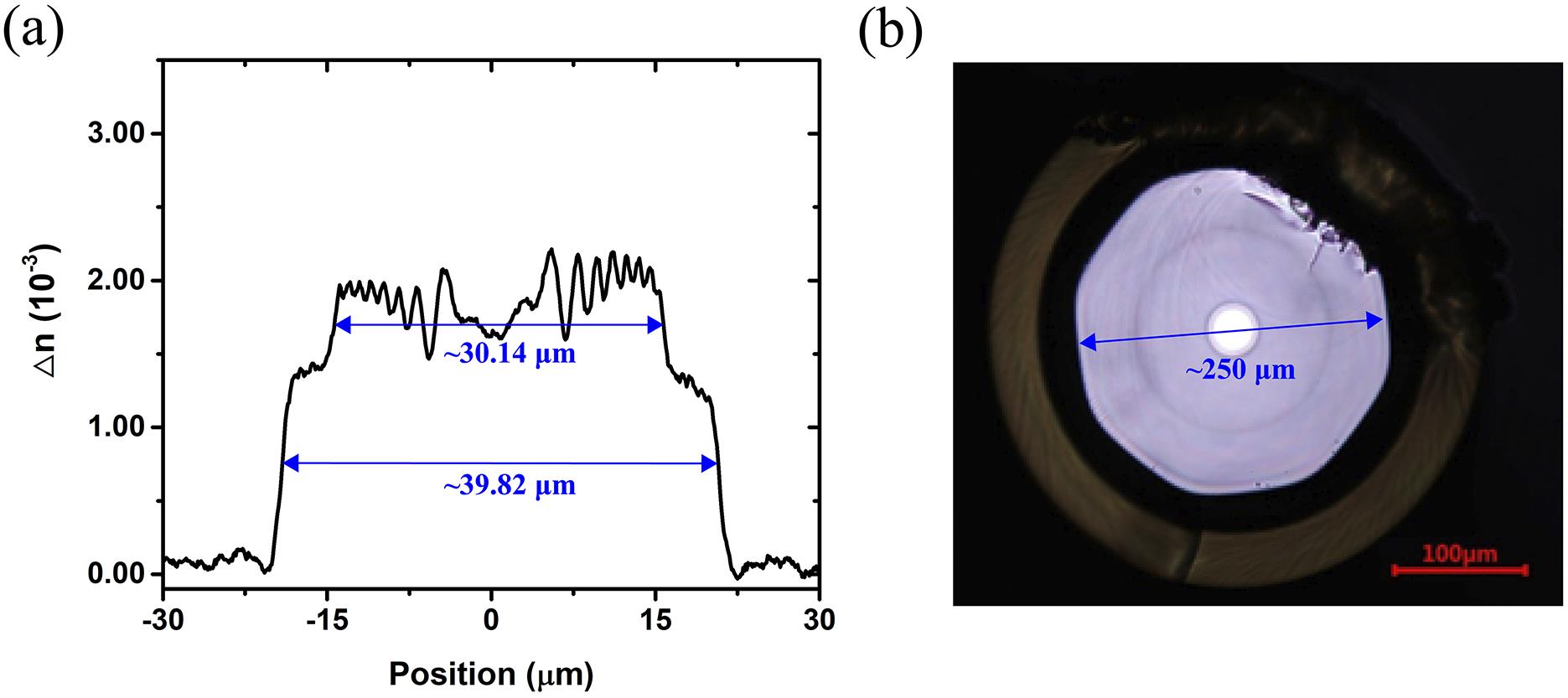
Figure 1.(a) Refractive index profile of the fiber across the core region; (b) cross-section photograph of the confined-doped fiber.
The experimental setup of the tandem-pumped confined-doped fiber amplifier is based on a master oscillator power amplifier scheme, as depicted in Figure 2. The seed laser is a conventional fiber oscillator employing ytterbium-doped fiber (YDF) with a core/inner-cladding diameter of 20/400 μm and core NA of approximately 0.065. In this fiber, only the LP01 and LP11 modes can be supported. The reflectance values of the high-reflectivity fiber Bragg grating (HR FBG) and output coupling fiber Bragg grating (OC FBG) are more than 99.9% and approximately 10% at approximately 1080 nm, respectively. The YDF is approximately 14-m-long and is spirally coiled on a water-cooled heat sink at approximately 20°C, the coiling diameter of which gradually increases from 10 cm (close to the HR FBG) to 16 cm (close to the OC FBG). The seed fiber laser operates at approximately 1080 nm and can deliver up to approximately 300 W output power. The 1018 nm pump laser module is based on the 7×1 beam combining technique[31], which consists of seven individual 1018 nm fiber oscillators. Each fiber oscillator exploits optical fiber with a core/inner-cladding diameter of 15/130 μm and is capable of delivering approximately 350 W output power. The seed laser and the pump laser are injected into the confined-doped fiber through a (6+1)×1 pump and signal combiner (PSC). The core/inner-cladding diameters of the PSC input and output pigtail fiber are 20/130 and 40/250 μm, respectively. The length of the confined-doped fiber is approximately 36 m. A cladding mode striper (CMS) is spliced after the confined-doped fiber to remove the cladding light. Finally, the laser is output through an end cap. The pigtail fibers of the CMS and the end cap are all based on germanium-doped fiber (GDF) with a core/inner-cladding diameter of 40/250 μm.
![]()
Figure 2.Experimental schematic of the confined-doped fiber amplifier (PSC, pump and signal combiner; YDF, ytterbium-doped fiber; CMS, cladding mode stripper).
3 Results and discussion
The seed laser power is set to approximately 70 W, and the output power from the confined-doped fiber amplifier as a function of the pump power is shown in Figure 3(a). The output power increases almost linearly with the pump power and reaches approximately 5.85 kW at the pump power of approximately 7.18 kW, corresponding to an optical-to-optical (O-O) efficiency of approximately 80.5%. The beam quality factor evolution of this confined-doped fiber amplifier as a function of the output power is shown in Figure 3(b). The beam quality factor first improves from 1.87 at approximately 500 W to 1.54 at approximately 3.21 kW. Then, the beam quality starts to degrade upon the onset of TMI at approximately 4.98 kW, reaching approximately 2.04 at the maximum output power. The output power could be further improved, but the beam quality shows dramatic degradation, making it less attractive for further power scaling.
![]()
Figure 3.(a) The output power and optical-to-optical efficiency as a function of the pump power; (b) the beam quality factor evolution as a function of the output power.
According to previous studies, increasing the power of the seed laser could lead to a higher TMI threshold[32,33]. With the aim of maintaining good beam quality of the confined-doped fiber amplifier at a higher power level, the impacts of the seed laser power on the TMI threshold of this confined-doped fiber amplifier are experimentally investigated. The seed laser power is successively set to approximately 70, 110, 140, 180 and 220 W, respectively. The TMI threshold and the extracted power (defined as the power difference between the TMI threshold and the seed laser power) at different seed powers are presented in Figure 4. As the seed power increases from approximately 70 W to approximately 220 W, the TMI threshold of the fiber amplifier increases from approximately 4.98 to 7.38 kW, and the extracted powers are respectively approximately 4.91, 5.82, 6.60, 7.17 and 7.16 kW at the seed powers of approximately 70, 110, 140, 180 and 220 W, respectively. Therefore, as the seed laser power increases, the TMI threshold improves significantly. However, when the seed laser power reaches 180 and 220 W, the extracted power slightly decreases. In this case, further increasing the seed laser power would not contribute to a much higher TMI threshold.
![]()
Figure 4.The TMI threshold and extracted power as a function of seed laser power.
In previous studies, the seed laser power does not have such a remarkable effect on the TMI threshold[33]. However, in the current study, the impact of the seed laser power seems very significant. Since the TMI threshold could be affected by a series of factors, such as (i) the seed laser power[32,33], (ii) the temporal stability/noise of the seed laser[34], (iii) the linewidth of the seed laser[35] and (iv) the mode purity of the seed laser[10], in order to find the dominant influencing factor, comparative investigations are systematically carried out.
To make the comparative experiments rigorous and reliable, we need to change one of the output characteristics of the seed laser each time without affecting the rest. Consequently, the bending loss is introduced to the seed laser for power control while not affecting the temporal and spectral properties. The output pigtail fiber of the seed laser is coiled to introduce the bending loss, and a CMS is integrated after the seed laser to remove the cladding light caused by the fiber bending, as shown in Figure 5. Considering that for fiber lasers based on fiber with a core/inner-cladding diameter of 20/400 μm, bending the fiber not only affects the output power but also may affect the mode purity of the laser. Hence, it is necessary to analyze the loss of HOMs in different bending states.
![]()
Figure 5.The experimental schematic of the power controllable seed laser based on the bending loss mechanism.
To this end, the spatially and spectrally resolved imaging (S2) method[36] is used to study the mode contents of the 20/400 μm fiber used in the seed laser at different bending diameters. In the measurement, a tunable fiber laser (TFL) and a charge-coupled device (CCD) are used, and the measurement system is shown in Figure 6. The fiber under test (FUT) is the same type as the fiber used for the fiber Bragg grating of the seed laser, and the length of its bending region is kept around approximately 1.1 m. The single-mode output pigtail of the tunable laser light source and the FUT is spliced with a slight core offset to excite the HOM components. Then the laser light output from the FUT is magnified by a 20× microscope objective (MO) lens and enters the CCD for spot intensity distribution measurement. In the experiment, the FUT is coiled with bending diameters of approximately 35, 20, 15 and 8 cm. Under each bending diameter of the FUT, the center wavelength of the tunable laser is gradually adjusted from 1075 to 1115 nm, with an interval of 0.1 nm, and the corresponding spot intensity distribution images are collected at each wavelength. The data processing method for the S2 measurement results refers to Ref. [37].
![]()
Figure 6.The experimental schematic of the S2 measurement (TFL, tunable fiber laser; FUT, fiber under test; MO, microscope objective; CCD, charge-coupled device).
The measurement results at different bending diameters are shown in Figure 7. By reconstructing the peaks at different differential mode group delays (DMGDs), it is found the DMGD range from approximately 0.06 to 0.22 ps/m corresponds to the LP11 mode, which is further used for calculating the multiple-path interference (MPI) of the LP11 mode. When the bending diameter is 35 cm, the MPI intensity is –13.88 dB. Under this circumstance, the intensity of the MPI is mainly determined by the HOM generated by the offset splicing. As the bending diameter decreases to 15 cm, the corresponding MPI decreases to –19.08 dB, indicating the HOM power is decreasing. When the bending diameter is further reduced to approximately 8 cm, the MPI drops to –37.60 dB, at which point the light intensity of the LP11 mode is too weak to reconstruct. The above measurement results show that as the fiber bending diameter decreases, the LP11 mode content decreases significantly, and when the bending diameter is less than 8 cm, a proportion of the LP11 mode is already negligible. Therefore, when changing the output power of the seed laser by bending the fiber, the HOM components in the seed laser can be simultaneously suppressed.
![]()
Figure 7.S2 measurement results when the bending diameter of the FUT is (a) 35 cm, (b) 20 cm, (c) 15 cm and (d) 8 cm.
Firstly, the seed laser is set to approximately 180 W (the corresponding pump current is 3.5 A). By coiling the fiber to bending states A–D (as listed in Table 1, where the state N represents ‘no bending’), the output power is subsequently decreased to 140 W (bending state A), 110 W (bending state B), 90 W (bending state C) and 70 W (bending state D) by coiling the pigtail fiber of the seed laser. In this case, the operation state of the seed laser remains unchanged, and thus the influences of the seed laser temporal property and linewidth can be ruled out. As a result, the extracted power is measured to be 7.17, 5.42, 4.54, 4.55 and 4.53 kW, when the seed laser power is 180, 140, 110, 90 and 70 W, respectively, as shown in Figure 8. The corresponding pump power is approximately 8.88, 6.73, 5.63 and 5.63 kW , and the corresponding O-O efficiency of the fiber amplifier remains around 80.6%. The extracted power remains almost unchanged when the seed laser power is between 70 and 110 W, which means the TMI threshold increment almost equals the increased seed laser power.
![]()
Figure 8.Extracted power at different seed laser powers.
| Bending state | A | B | C | D | N |
|---|---|---|---|---|---|
| Bending diameter/m | ~0.15 | ~0.09 | ~0.08 | ~0.06 | No bending |
| Bending length/m | ~1.0 | ~1.0 | ~0.75 | ~0.5 | |
| Seed power/W | 140 | 110 | 90 | 70 | 180 |
Table 1. Bending diameter/length and the seed laser power at different bending states.
Then, we keep the bending diameter (bending state B) fixed and change the output power by tuning the pump current of the seed laser. When the output power is respectively set to 110 W (pump current: 3.5 A), 180 W (pump current: 4.4 A) and 220 W (pump current: 5.0 A), the extracted power of the confined-doped fiber amplifier is corresponding to 4.54, 4.53 and 4.53 kW, respectively, as shown in Figure 8. In this case, the corresponding linewidths of the seed laser are 2.32, 2.57 and 2.78 nm. Therefore, there is almost no dependence of the TMI threshold on the seed laser linewidth in this broad linewidth fiber amplifier. According to the above results, the influence of the seed laser linewidth and output power on the dramatic TMI threshold change can be basically excluded in the current laser system.
Furthermore, the influences of the HOM components in the seed laser on the TMI threshold are theoretically analyzed. In previous studies, the higher the HOM contents in the seed laser, the lower the TMI threshold[38–40], where the HOM components were regraded to be coherent with the fundamental mode. The seed laser used in this work is a broadband oscillator, and it can be considered that the fundamental mode could only interfere with the HOM component (HOM-A) with a small frequency shift, thus affecting the TMI threshold. While the fundamental mode cannot interfere with the HOM component (HOM-B) with no frequency shift, the fundamental mode and HOM-B are superposed incoherent and amplified separately in the amplifier, as assumed by Chu et al.[41].
Since only the LP01 and LP11 modes are supported in the pigtail fiber of the seed laser, only the above two modes are considered in the simulation. A theoretical mode for the confined-doped fiber amplifier is established based on the rate equations while considering the transverse spatial-hole burning[42]. In the simulation, it is assumed that the fiber amplifier operates below the TMI threshold. The nonlinear mode coupling caused by the thermally refractive index grating and mode interference between different transverse modes are neglected. In the proposed simulation, the population inversion in the steady state can be described as follows:
The gain of each mode is given by the following:
where
The propagation equation is given by the following:
Assuming the fiber amplifier operates below the TMI threshold, according to the theory proposed by Dong[43], the total gain of HOM-A (
where C21 is the nonlinear coupling coefficient[44],
The seed power is set to 100 W, and the mode purity varies from 0.6 to 1. Other parameters are listed in Table 2.
| Parameter | Value | Parameter | Value |
|---|---|---|---|
| rcore | 20 μm | rclad | 125 μm |
| λp | 1018 nm | λs | 1080 nm |
| 9.44 × 10⁻²⁶ m2 | 7.30 × 10⁻²⁵ m2 | ||
| 2.29 × 10⁻²⁷ m2 | 2.82 × 10⁻²⁵ m2 | ||
| τ | 840 μs | n | 4.94 × 1025 m-3 |
| L | 36 m | ||
| 1.38 W/K |
Table 2. The main parameters of the fiber amplifier.
The simulation results are shown in Figure 9. As the mode purity of the seed laser decreases, the TMI threshold of the amplifier gradually increases, as shown in Figure 9(a): in the case of pure fundamental mode seed laser injection, the TMI threshold of the amplifier is approximately 3.60 kW, and the output laser is in the pure fundamental mode as well. When the mode purity of the seed laser drops to 0.6, the TMI threshold rises to approximately 6.16 kW (with ~4.77 kW fundamental mode power and ~1.39 kW LP11 mode power). Compared with the pure fundamental mode seed laser case, the TMI threshold of the amplifier has increased by approximately 71.11%. At the same time, the output power of the fundamental mode laser is approximately 4.77 kW; compared with the pure fundamental mode injection case (~3.60 kW), the power of the fundamental mode has increased by approximately 32.50%. Moreover, as the mode purity of the seed laser decreases from 90.0% to 60.0%, the mode purity of the output laser decreases from 92.42% to 77.44%, but it is still higher than that of the seed laser owing to the gain-filtering effect, as shown in Figure 9(b).
![]()
Figure 9.(a) TMI threshold and the power of the fundamental mode upon the onset of TMI and (b) the mode purity of the output laser as a function of the seed laser mode purity (simulation results).
As validated by the simulation, the TMI threshold is significantly improved by introducing HOM content in the seed laser. On the one hand, the introduction of HOMs would inevitably compete with the fundamental mode. According to Equation (5), this will result in the power reduction of P1(z) and lead to a smaller total gain of HOM-A (
![]()
Figure 10.The pump gain distribution of HOM-A along the fiber when the seed mode purities are 0.6 and 1.
It is to be noted that this is a preliminary theoretical analysis of the TMI threshold in a confined-doped fiber amplifier seeded by laser with a certain amount of HOM content. The actual mode dynamics could be much more complicated. For instance, more HOMs could be excited at the splicing point (resulting from core NA mismatch/core offset splicing between the passive fiber and the confined-doped fiber). Therefore, other HOMs could also compete with HOM-A, and when the TMI occurs, besides the mode coupling between the fundamental mode and LP11 mode, there could be mode coupling between the fundamental mode and other HOMs, and even mode coupling between HOMs. Therefore, the current simulation could reveal the possible mechanism for the dramatic change in TMI threshold, but differences exist between the simulated and experimental results.
Moreover, we are aware of the reported experimental study by Chu et al.[41]. In that work, by introducing HOM content into the fiber amplifier system through offset splicing, the TMI threshold was increased from approximately 3.0 to 3.5 kW, where the static beam quality degradation first appeared before the onset of TMI. However, in the current work, the beam quality is not degraded before the TMI occurs. According to the simulation results in Figure 9(b), the mode purity of the output laser from the amplifier is 77.44%, 81.79%, 86.65% and 92.42% when the corresponding mode purity of the seed laser is 60.0%, 70.0%, 80.0% and 90.0%, respectively. Therefore, the mode purity of the output laser is improved compared with the seed laser owing to the gain-filtering effect of the confined-doped fiber. Consequently, the confined-doped fiber amplifier could take full advantage of the seed laser control technique, that is, introducing HOM contents into the amplifier for TMI mitigation without seriously degrading the beam quality.
According to the above experimental and simulation results, the seed power of 180 W (without bending the seed laser pigtail fiber) is used for further power amplification. Under this circumstance, the output power as a function of the pump power of the fiber amplifier is as shown in Figure 11. The maximum output power of 7.49 kW is obtained at the pump power of 9.07 kW, which is the highest output power ever reported in a forward pumped confined-doped fiber amplifier. The O-O efficiency of the fiber amplifier is generally stable, which is approximately 80.6% at the maximum output power. The normalized output spectra at different output powers are depicted in Figure 11(b), and the 3-dB linewidth of the output laser increases from 2.32 nm of the seed laser to 4.08 nm at the maximum output power. The wing-like broadening of the output spectra is due to the intermodal four-wave mixing. Asymmetric spectral broadening is also observed, and the broadening in the long-wavelength side is much more severe, which results from the temperature rise induced red-shifting within the fiber. The signal-to-Raman ratio of the output spectrum at the maximum output power is approximately 31 dB. Therefore, further power scaling is limited by the stimulated Raman scattering (SRS).
![]()
Figure 11.(a) Output power as a function of the pump power; (b) output spectra at different output powers.
The beam quality factors of the fiber amplifier at different output powers are shown in Figure 12. The beam quality factor is M2 = 2.22 at the output power of approximately 500 W, and is improved to M2 = 1.75 at the output power of 4.98 kW owing to the gain-filtering effect of the confined-doped fiber. Then, the beam quality factor remains around 1.8 during the power scaling process and reaches 1.83 at the output power of 7.49 kW.
![]()
Figure 12.The beam quality factor evolution as a function of the output power.
4 Conclusion
In this work, a high-brightness 7.49 kW confined-doped fiber amplifier is demonstrated by mitigating the TMI effect. The effects of the seed laser output power and mode purity on the TMI threshold are comparatively studied. It is revealed that the mode purity of the seed laser could significantly influence the TMI threshold of the fiber amplifier, the possible reason for which is further explained and verified through simulation analysis. Furthermore, by using the seed laser with a certain amount of HOM content, a maximum output power of 7.49 kW is obtained with the O-O efficiency of 80.6%. Benefitting from the confined-doped fiber design, the beam quality is relatively well preserved, reaching M2 = 1.83 at the maximum output power. This work provides a practical solution for improving the TMI threshold of fiber amplifiers while preserving good beam quality with the confined-doped fiber. The beam quality could be further improved by optimizing the confined-doped fiber relative doping ratio and refractive index profile. Moreover, with the aid of the mode decomposition technique, the effects of HOM contents and their amount on the TMI threshold could be further investigated quantitatively in the next step through careful experimental design and theoretical analysis.
References
[1] M. N. Zervas, C. A. Codemard. IEEE J. Sel. Top. Quantum Electron., 20, 219(2014).
[2] W. Shi, Q. Fang, X. Zhu, R. A. Norwood, N. Peyghambarian. Appl. Opt., 53, 6554(2014).
[3] D. J. Richardson, J. Nilsson, W. A. Clarkson. J. Opt. Soc. Am. B, 27, B63(2010).
[4] M. Jiang, H. Wu, Y. An, T. Hou, Q. Chang, L. Huang, J. Li, R. Su, P. Zhou. PhotoniX, 3(2022).
[5] C. Jauregui, C. Stihler, J. Limpert. Adv. Opt. Photon., 12, 429(2020).
[6] P. Ma, H. Xiao, W. Liu, H. Zhang, X. Wang, J. Leng, P. Zhou. High Power Laser Sci. Eng., 9, e45(2021).
[7] H.-J. Otto, N. Modsching, C. Jauregui, J. Limpert, A. TünnermannAdvanced Solid State Lasers. , , , , and , in (), paper AM5A.44.(2014).
[8] R. Tao, P. Ma, X. Wang, Z. Pu, Z. Liu. J. Opt., 17, 045504(2015).
[9] P. Ma, H. Xiao, D. Meng, W. Liu, R. Tao, J. Leng, Y. Ma, R. Su, P. Zhou, Z. Liu. High Power Laser Sci. Eng, 6, e57(2018).
[10] Z. Li, Z. Huang, X. Xiang, X. Liang, H. Lin, S. Xu, Z. Yang, J. Wang, F. Jing. Photon. Res., 5, 77(2017).
[11] R. Tao, P. Ma, X. Wang, P. Zhou, Z. Liu. Laser Phys. Lett., 14, 025002(2016).
[12] A. V. Smith, J. J. Smith. Opt. Express, 21, 15168(2013).
[13] B. G. Ward. Opt. Lett., 40, 542(2015).
[14] L. Dong, X. Peng, J. Li. J. Opt. Soc. Am. B, 24, 1689(2007).
[15] Y. Wang, G. Chen, J. Li. High Power Laser Sci. Eng., 6, e40(2018).
[16] K.-J. Lim, S. K.-W. Seah, J. Y. E. Ye, W. W. Lim, C.-P. Seah, Y.-B. Tan, S. Tan, H. Lim, R. Sidharthan, A. R. Prasadh, C.-J. Chang, S. Yoo, S.-L. Chua. Photon. Res., 8, 1599(2020).
[17] Y. Ye, X. Lin, X. Xi, C. Shi, B. Yang, H. Zhang, X. Wang, J. Li, X. Xu. High Power Laser Sci. Eng., 9(2021).
[18] M. Laurila, M. M. Jørgensen, K. R. Hansen, T. T. Alkeskjold, J. Broeng, J. Lægsgaard. Opt. Express, 20, 5742(2012).
[19] F. Stutzki, F. Jansen, T. Eidam, A. Steinmetz, C. Jauregui, J. Limpert, A. Tünnermann. Opt. Lett., 36, 689(2011).
[20] J. Song, S. Ren, G. Wang, H. Yang, Y. Chen, P. Ma, W. Liu, L. Huang, Z. Pan, P. Zhou. J. Lightwave Technol., 40, 5668(2022).
[21] S. Ikoma, H. K. Nguyen, M. Kashiwagi, K. Uchiyama, K. Shima, D. Tanaka. Proc. SPIE, 10083, 100830Y(2017).
[22] J. R. Marciante. IEEE J. Sel. Top. Quantum Electron., 15(2009).
[23] C. P. Seah, W. Y. W. Lim, S. L. ChuaAdvanced Solid State Laser. , , and , in (), paper AM2A.2.(2018).
[24] B. Wang, L. Pang, J. Liu. Proc. SPIE, 11427, 114271X(2020).
[25] H. Lü, P. Zhou, X. Wang, Z. Jiang. Opt. Express, 20, 6456(2012).
[26] M. Gong, Y. Yuan, C. Li, P. Yan, H. Zhang, S. Liao. Opt. Express, 15, 3236(2007).
[27] J. R. Marciante, R. G. Roides, V. V. Shkunov, D. A. Rockwell. Opt. Lett., 35, 1828(2010).
[28] F. Zhang, Y. Wang, X. Lin, Y. Cheng, Z. Zhang, Y. Liu, L. Liao, Y. Xing, L. Yang, N. Dai, H. Li, J. Li. Opt. Express, 27, 20824(2019).
[29] Z. Huang, Q. Shu, Y. Luo, R. Tao, X. Feng, Y. Liu, H. Lin, J. Wang, F. Jing. J. Opt. Soc. Am. B, 38, 2945(2021).
[30] H. Wu, R. Li, H. Xiao, L. Huang, H. Yang, Z. Pan, J. Leng, P. Zhou. Opt. Express, 29, 31337(2021).
[31] R. Li, H. Xiao, J. Leng, Z. Chen, J. Xu, J. Wu, P. Zhou. Laser Phys. Lett., 14, 125102(2017).
[32] L. Huang, R. Tao, C. Shi, D. Meng, H. Zhang, P. Ma, X. Wang, P. Zhou. IEEE Photonics J., 10, 1504312(2018).
[33] R. Tao, X. Wang, P. Zhou, Z. Liu. J. Opt., 19, 065202(2017).
[34] K. R. Hansen, T. T. Alkeskjold, J. Broeng, J. Lægsgaard. Opt. Express, 21, 1944(2013).
[35] S. Ren, W. Lai, G. Wang, W. Li, J. Song, Y. Chen, P. Ma, W. Liu, P. Zhou. Opt. Express, 30, 7845(2022).
[36] J. W. Nicholson, A. D. Yablon, S. Ramachandran, S. Ghalmi. Opt. Express, 16, 7233(2008).
[37] X. Chen, L. Huang, H. Yang, X. Xi, Y. An, Z. Yan, Y. Chen, Z. Pan, P. Zhou. Opt. Laser Technol., 157, 108668(2023).
[38] B. Ward, C. Robin, I. Dajani. Opt. Express, 20, 11407(2012).
[39] M. Karow, H. Tünnermann, J. Neumann, D. Kracht, P. Weßels. Opt. Lett., 37, 4242(2012).
[40] R. Tao, X. Wang, P. Zhou. IEEE J. Sel. Top. Quantum Electron., 24, 0903319(2018).
[41] Q. Chu, R. Tao, C. Li, H. Lin, Y. Wang, C. Guo, J. Wang, F. Jing, C. Tang. Sci. Rep., 9, 9396(2019).
[42] Z. Jiang, J. R. Marciante. J. Opt. Soc. Am. B, 25, 247(2008).
[43] L. Dong. J. Lightwave Technol., 40, 4795(2022).
[44] H. Li, L. Huang, H. Wu, Z. Pan, P. Zhou. Photonics, 9, 577(2022).
[45] A. V. Smith, J. J. Smith. Opt. Express, 20, 24545(2012).


Set citation alerts for the article
Please enter your email address

© Copyright 2018-2021 | Chinese Laser Press. All Rights Reserved 沪ICP备15018463号-20