• Chinese Optics Letters
  • Vol. 19, Issue 6, 060002 (2021)
Zhe Wang1、2、3, Chaohua Wu4、5, Zhiwei Fang6、*, Min Wang6, Jintian Lin1, Rongbo Wu1、2, Jianhao Zhang1、2, Jianping Yu1、2, Miao Wu6, Wei Chu6, Tao Lu7, Gang Chen4、5、**, and Ya Cheng1、5、6、***
Author Affiliations
  • 1State Key Laboratory of High Field Laser Physics and CAS Center for Excellence in Ultra-intense Laser Science, Shanghai Institute of Optics and Fine Mechanics (SIOM), Chinese Academy of Sciences (CAS), Shanghai 201800, China
  • 2Center of Materials Science and Optoelectronics Engineering, University of Chinese Academy of Sciences, Beijing 100049, China
  • 3School of Physical Science and Technology, ShanghaiTech University, Shanghai 200031, China
  • 4State Key Laboratory of Quantum Optics and Quantum Optics Devices, Institute of Laser Spectroscopy, Shanxi University, Taiyuan 030006, China
  • 5Collaborative Innovation Center of Extreme Optics, Shanxi University, Taiyuan 030006, China
  • 6The Extreme Optoelectromechanics Laboratory (XXL), School of Physics and Electronic Science, East China Normal University, Shanghai 200241, China
  • 7Department of Electrical and Computer Engineering, University of Victoria, Victoria BC V8P 5C2, Canada
  • show less
    DOI: 10.3788/COL202119.060002 Cite this Article Set citation alerts
    Zhe Wang, Chaohua Wu, Zhiwei Fang, Min Wang, Jintian Lin, Rongbo Wu, Jianhao Zhang, Jianping Yu, Miao Wu, Wei Chu, Tao Lu, Gang Chen, Ya Cheng. High-quality-factor optical microresonators fabricated on lithium niobate thin film with an electro-optical tuning range spanning over one free spectral range [Invited][J]. Chinese Optics Letters, 2021, 19(6): 060002 Copy Citation Text show less
    Process flow of fabricating an on-chip LN racetrack resonator integrated with Cr microelectrodes. (a), (b) Patterning the Cr thin film into a stripe mask using femtosecond laser microfabrication. (c) Etching of the LNOI layer by chemo-mechanical polishing. (d), (e) Selective removal of the stripe Cr mask on the LN racetrack resonator using femtosecond laser ablation. (f) Reducing the thickness of LN racetrack resonator by a post chemo-mechanical polishing, which leads to the smooth top surface on the LN waveguide.
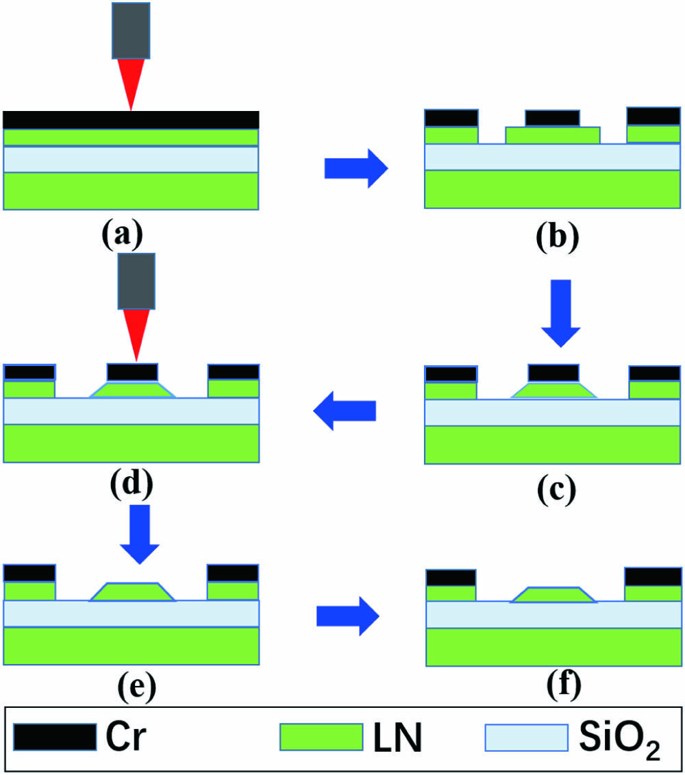
    Fig. 1. Process flow of fabricating an on-chip LN racetrack resonator integrated with Cr microelectrodes. (a), (b) Patterning the Cr thin film into a stripe mask using femtosecond laser microfabrication. (c) Etching of the LNOI layer by chemo-mechanical polishing. (d), (e) Selective removal of the stripe Cr mask on the LN racetrack resonator using femtosecond laser ablation. (f) Reducing the thickness of LN racetrack resonator by a post chemo-mechanical polishing, which leads to the smooth top surface on the LN waveguide.
    (a) Top view optical micrograph of the on-chip LN racetrack resonator integrated with Cr electrodes. Zoom-in optical micrographs of the (b) curved and (c) straight waveguides. (d) Distributions of the optical (TE) field and electrical field overlapping each other simulated using COMSOL. The arrows indicate the direction of the electric field.
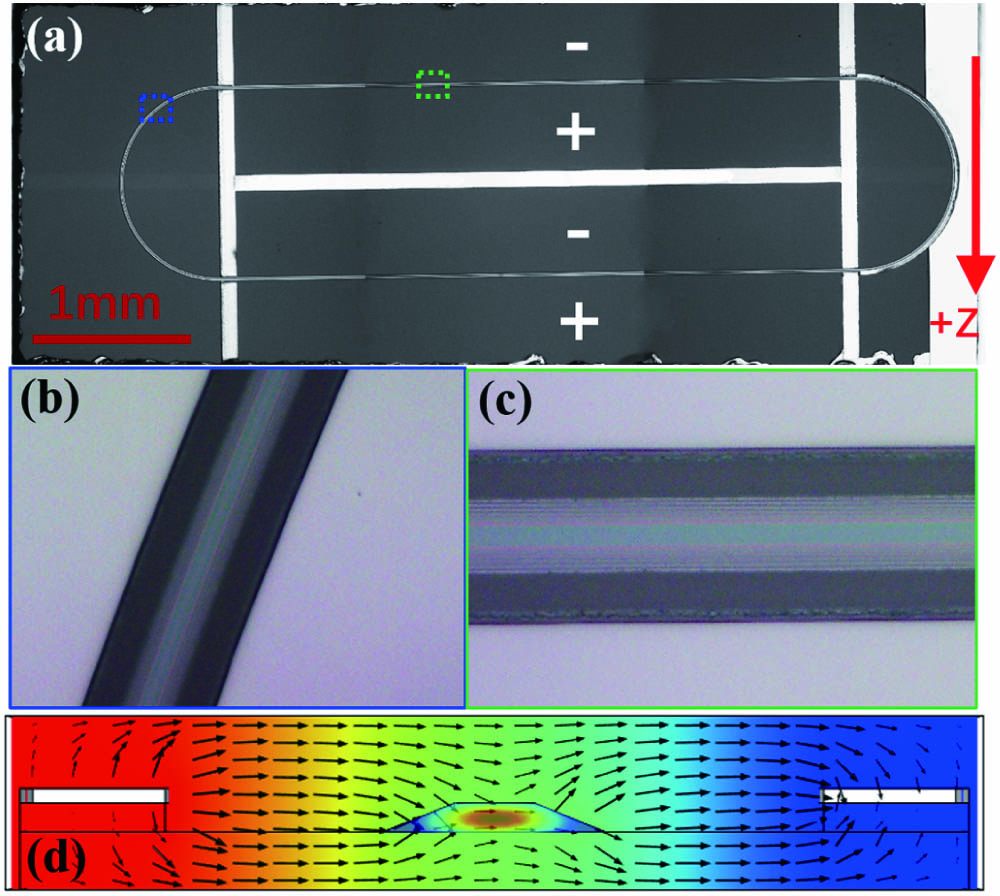
    Fig. 2. (a) Top view optical micrograph of the on-chip LN racetrack resonator integrated with Cr electrodes. Zoom-in optical micrographs of the (b) curved and (c) straight waveguides. (d) Distributions of the optical (TE) field and electrical field overlapping each other simulated using COMSOL. The arrows indicate the direction of the electric field.
    (a) Picture of the LN racetrack resonator integrated with Cr electrodes. (b) Zoom-in image of the LN racetrack resonator integrated with Cr electrodes. (c) Schematic of the experimental setup for characterizing the Q factor and tunability of the device.
    Fig. 3. (a) Picture of the LN racetrack resonator integrated with Cr electrodes. (b) Zoom-in image of the LN racetrack resonator integrated with Cr electrodes. (c) Schematic of the experimental setup for characterizing the Q factor and tunability of the device.
    (a) Transmission spectrum of the LN ractrack resonator. (b) The Lorentz fitting (red curve) reveals a loaded Q factor of 1.4×10⁶, corresponding to an intrinsic Q factor of 2.8×10⁶ as measured at the 1547.93 nm wavelength; the linewidth of 1.1 pm is shown in inset.
    Fig. 4. (a) Transmission spectrum of the LN ractrack resonator. (b) The Lorentz fitting (red curve) reveals a loaded Q factor of 1.4×10⁶, corresponding to an intrinsic Q factor of 2.8×10⁶ as measured at the 1547.93 nm wavelength; the linewidth of 1.1 pm is shown in inset.
    (a) Calculated effective index neff and (b) group index ng of the optical mode in Fig. 2(d) for the wavelength range between 1550 and 1600 nm.
    Fig. 5. (a) Calculated effective index neff and (b) group index ng of the optical mode in Fig. 2(d) for the wavelength range between 1550 and 1600 nm.
    (a) Resonance wavelength continuously red shifts with the increasing voltage. (b) The linear fit reveals an electrical tuning rate of ∼0.46 pm/V and indicates that the tuning range spans over a full FSR.
    Fig. 6. (a) Resonance wavelength continuously red shifts with the increasing voltage. (b) The linear fit reveals an electrical tuning rate of ∼0.46 pm/V and indicates that the tuning range spans over a full FSR.
    Zhe Wang, Chaohua Wu, Zhiwei Fang, Min Wang, Jintian Lin, Rongbo Wu, Jianhao Zhang, Jianping Yu, Miao Wu, Wei Chu, Tao Lu, Gang Chen, Ya Cheng. High-quality-factor optical microresonators fabricated on lithium niobate thin film with an electro-optical tuning range spanning over one free spectral range [Invited][J]. Chinese Optics Letters, 2021, 19(6): 060002
    Download Citation