
Zhe Wang, Chaohua Wu, Zhiwei Fang, Min Wang, Jintian Lin, Rongbo Wu, Jianhao Zhang, Jianping Yu, Miao Wu, Wei Chu, Tao Lu, Gang Chen, Ya Cheng, "High-quality-factor optical microresonators fabricated on lithium niobate thin film with an electro-optical tuning range spanning over one free spectral range [Invited]," Chin. Opt. Lett. 19, 060002 (2021)
- Chinese Optics Letters
- Vol. 19, Issue 6, 060002 (2021)
Abstract
1. Introduction
Whispering gallery mode (WGM) optical microresonators play a crucial role in both photonic research and applications owing to the strong confinement of light fields resulting from the characteristic high quality (Q) factors[
Here, we demonstrate high-Q optical microresonators fabricated on lithium niobate (LN) thin film (900-nm-thick) with an electro-optical (EO) tuning range spanning over one free spectral range (FSR). The advantage of choosing LN as the substrate material is the strong EO property. In particular, our fabrication technique based on photolithography assisted chemo-mechanical etching (PLACE) allows us to define the mask pattern of a racetrack WGM resonator with a footprint size of
2. Materials and Methods
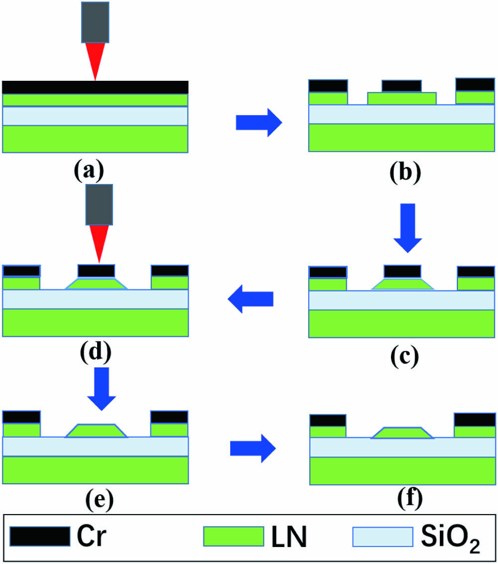
In our experiment, the on-chip LN racetrack resonator integrated with Cr electrodes was fabricated on a commercially available X-cut LN on insulator (LNOI) wafer (NANOLN, Jinan Jingzheng Electronics Co., Ltd.). The LN thin film with a thickness of 900 nm was bonded onto a silica layer with a thickness of ∼2 µm, and the silica layer was grown on a 0.5-mm-thick LN substrate. A 600-nm-thick chromium (Cr) film was further deposited on the top surface of the LNOI by magnetron sputtering. The fabrication process includes four steps, as illustrated in Fig. 1. Firstly, the Cr film on the LNOI sample was patterned into a stripe-shaped mask using a space-selective femtosecond laser (PHAROS, LIGHT CONVERSION Inc.). Subsequently, the chemo-mechanical polishing (CMP) process was performed to fabricate the LN waveguide using a wafer polishing machine (NUIPOL802, Kejing Inc.). The LN thin film protected by the Cr mask was preserved after the CMP process, whereas the remaining LN in the opening area was completely removed. This step allows us to create LN waveguides with extremely smooth sidewalls, ensuring high-Q factors for the fabricated microresonators[
Sign up for Chinese Optics Letters TOC. Get the latest issue of Chinese Optics Letters delivered right to you!Sign up now
![]()
Figure 1.Process flow of fabricating an on-chip LN racetrack resonator integrated with Cr microelectrodes. (a), (b) Patterning the Cr thin film into a stripe mask using femtosecond laser microfabrication. (c) Etching of the LNOI layer by chemo-mechanical polishing. (d), (e) Selective removal of the stripe Cr mask on the LN racetrack resonator using femtosecond laser ablation. (f) Reducing the thickness of LN racetrack resonator by a post chemo-mechanical polishing, which leads to the smooth top surface on the LN waveguide.
![]()
Figure 2.(a) Top view optical micrograph of the on-chip LN racetrack resonator integrated with Cr electrodes. Zoom-in optical micrographs of the (b) curved and (c) straight waveguides. (d) Distributions of the optical (TE) field and electrical field overlapping each other simulated using COMSOL. The arrows indicate the direction of the electric field.
Figure 2(a) presents the top view of the on-chip LN racetrack resonator integrated with the Cr electrodes. The diameter of the two half-circles of the racetrack resonator is 1.2 mm, and the length of the straight arms of the racetrack is 4 mm. Therefore, the perimeter of the microresonator is ∼11.77 mm. Figures 2(b) and 2(c) present the zoom-in images of the curved and straight waveguides of the LN racetrack resonator, respectively. The surface roughness on the waveguides was determined with an atomic force microscope (AFM) to be subnanometer[
3. Results
Figure 3(a) presents the digital-camera-captured picture of the racetrack resonator as compared with a one-yuan Renminbi coin. The zoom-in optical micrograph in Fig. 3(b) further shows the details of the racetrack resonator and the Cr electrodes as well as the aluminum wire (diameter ∼25 µm) connecting the Cr electrodes to the voltage generator. To characterize the tunability of the LN racetrack resonator, we used an experimental setup, as illustrated in Fig. 3(c). Here, a tunable laser (TLB-6728, Newport Inc.) was used as the light source. To enable efficient coupling of the light into the racetrack microresonator, we first fabricated a straight waveguide on another LNOI wafer. The straight waveguide has the same geometric parameters such as the cross sectional shape, thickness, and width as that of the waveguide in the LN racetrack resonator. The light from the tunable laser was coupled into the straight waveguide using a lensed fiber. The straight waveguide was then brought close to the racetrack resonator from the top to allow for evanescent coupling, as shown in Fig. 3(c). Due to the same geometric parameters of the straight waveguide and the racetrack waveguide, phase matching can be ensured to enable efficient coupling between them. The polarization state of the input light was adjusted using an in-line fiber polarization controller. The output of the LN waveguide was connected to a photodetector (New Focus 1811-FC-AC, Newport Inc.) using a lensed fiber for measuring the transmission spectrum and the Q factor of the racetrack resonator. A programmable linear direct current (DC) stabilized power source (IPMP500-0.6L, INTERLOCK Technologies Inc.) was used as the voltage generator, which provided a variable voltage ranging from −100 V to 100 V.
![]()
Figure 3.(a) Picture of the LN racetrack resonator integrated with Cr electrodes. (b) Zoom-in image of the LN racetrack resonator integrated with Cr electrodes. (c) Schematic of the experimental setup for characterizing the Q factor and tunability of the device.
Figure 4(a) shows the measured transmission spectrum in the wavelength range between 1544 and 1552 nm. The resonance lines appeared regularly spaced, indicating that mostly the fundamental mode is excited in the LN racetrack resonator. This should be a result of the same geometric parameters of the upper straight waveguide and the lower racetrack waveguide, as shown in Fig. 3(c). In this case, the spatial mode profiles in the two waveguides can most efficiently overlap. Thus, as the fundamental mode is excited in the upper waveguide with the lensed fiber, the same fundamental mode will be excited in the racetrack resonator as well. As shown in Fig. 4(b), the FSR of the microresonator was determined to be 86 pm. One of the WGMs at the resonant wavelength of 1547.93 nm was chosen for the measurement of the loaded Q factor
![]()
Figure 4.(a) Transmission spectrum of the LN ractrack resonator. (b) The Lorentz fitting (red curve) reveals a loaded Q factor of
Numerical simulations were performed using COMSOL to reveal the optical mode profile in our LN waveguide [see Fig. 2(d)]. In particular, the calculated effective index
![]()
Figure 5.(a) Calculated effective index neff and (b) group index ng of the optical mode in Fig.
Finally, we carried out the real-time tuning of the racetrack microresonator by adding a tunable electric voltage on the Cr microelectrodes. Figure 6(a) shows a group of transmission spectra recorded near the 1550 nm wavelength at various electric voltages in the range from
![]()
Figure 6.(a) Resonance wavelength continuously red shifts with the increasing voltage. (b) The linear fit reveals an electrical tuning rate of ∼0.46 pm/V and indicates that the tuning range spans over a full FSR.
4. Discussions
This is the first attempt of fabricating a large WGM microresonator on an LNOI using the PLACE fabrication technique. Before, we have shown that freestanding microdisks with diameters of ∼100 µm fabricated on the LNOI substrates using the PLACE technique can easily achieve Q factors above 107[
5. Conclusions
To conclude, we have demonstrated high-Q optical microresonators fabricated on LN thin film with an EO tuning range spanning over a full FSR. The EO tunable racetrack resonator of the perimeter above 1 cm features an FSR of ∼86 pm, an intrinsic Q factor of
References
[1] K. J. Vahala. Optical microcavities. Nature, 424, 839(2003).
[2] M. Cai, O. Painter, K. J. Vahala. Observation of critical coupling in a fiber taper to a silica-microsphere whispering-gallery mode system. Phys. Rev. Lett., 85, 74(2000).
[3] M. Soltani, S. Yegnanarayanan, A. Adibi. Ultra-high Q planar silicon microdisk resonators for chip-scale silicon photonics. Opt. Express, 15, 4694(2007).
[4] J. Lin, Y. Xu, Z. Fang, M. Wang, J. Song, N. Wang, L. Qiao, W. Fang, Y. Cheng. Fabrication of high-Q lithium niobate microresonators using femtosecond laser micromachining. Sci. Rep., 5, 8072(2015).
[5] M. Kuwata-Gonokami, R. H. Jordan, A. Dodabalapur, H. E. Katz, M. L. Schilling, R. E. Slusher, S. Ozawa. Polymer microdisk and microring lasers. Opt. Lett., 20, 2093(1995).
[6] J. Ward, O. Benson. WGM microresonators: sensing, lasing and fundamental optics with microspheres. Laser Photon. Rev., 5, 553(2011).
[7] A. L. Gaeta, M. Lipson, T. J. Kippenberg. Photonic-chip-based frequency combs. Nat. Photon., 13, 158(2019).
[8] H. Lee, T. Chen, J. Li, K. Y. Yang, S. Jeon, O. Painter, K. J. Vahala. Chemically etched ultrahigh-Q wedge-resonator on a silicon chip. Nat. Photon., 6, 369(2012).
[9] K. Y. Yang, D. Y. Oh, S. H. Lee, Q. F. Yang, X. Yi, B. Shen, H. Wang, K. Vahala. Bridging ultrahigh-Q devices and photonic circuits. Nat. Photon., 12, 297(2018).
[10] J. Liu, E. Lucas, A. S. Raja, J. He, J. Riemensberger, R. N. Wang, M. Karpov, H. Guo, R. Bouch, T. J. Kippenberg. Photonic microwave generation in the X- and K-band using integrated soliton microcombs. Nat. Photon., 14, 486(2020).
[11] D. T. Spencer, T. Drake, T. C. Briles, J. Stone, L. C. Sinclair, C. Fredrick, Q. Li, D. Westly, B. Robert Ilic, A. Bluestone, N. Volet, T. Komljenovic, L. Chang, S. H. Lee, D. Y. Oh, M.G. Suh, K. Y. Yang, M. H. P. Pfeiffer, T. J. Kippenberg, E. Norberg, L. Theogarajan, K. Vahala, N. R. Newbury, K. Srinivasan, J. E. Bowers, S. A. Diddams, S. B. Papp. An optical-frequency synthesizer using integrated photonics. Nature, 557, 81(2018).
[12] M. G. Suh, Q. F. Yang, K. Y. Yang, X. Yi, K. J. Vahala. Microresonator soliton dual-comb spectroscopy. Science, 354, 600(2016).
[13] J. Li, M. G. Suh, K. Vahala. Microresonator Brillouin gyroscope. Optica, 4, 346(2017).
[14] Z. L. Newman, V. Maurice, T. Drake, J. R. Stone, T. C. Briles, D. T. Spencer, C. Fredrick, Q. Li, D. Westly, B. R. Ilic, B. Shen, M. Suh, K. Y. Yang, C. Johnson, D. M. S. Johnson, L. Hollberg, K. J. Vahala, K. Srinivasan, S. A. Diddams, J. Kitching, S. B. Papp, M. T. Hummon. Architecture for the photonic integration of an optical atomic clock. Optica, 6, 680(2019).
[15] Q. F. Yang, B. Shen, H. Wang, M. Tran, Z. Zhang, K. Y. Yang, L. Wu, C. Bao, J. Bowers, A. Yariv, K. Vahala. Vernier spectrometer using counterpropagating soliton microcombs. Science, 363, 965(2019).
[16] M. Zhang, B. Buscaino, C. Wang, A. Shams-Ansari, C. Reimer, R. Zhu, J. M. Kahn, M. Lončar. Broadband electro-optic frequency comb generation in a lithium niobate microring resonator. Nature, 568, 373(2019).
[17] K. Luke, P. Kharel, C. Reimer, L. He, M. Lončar, M. Zhang. Wafer-scale low-loss lithium niobate photonic integrated circuits. Opt. Express, 28, 24452(2020).
[18] J. Wang, F. Bo, S. Wan, W. Li, F. Gao, J. Li, G. Zhang, J. Xu. High-Q lithium niobate microdisk resonators on a chip for efficient electro-optic modulation. Opt. Express, 23, 23072(2015).
[19] Z. Fang, Y. Xu, M. Wang, L. Qiao, J. Lin, W. Fang, Y. Cheng. Monolithic integration of a lithium niobate microresonator with a free-standing waveguide using femtosecond laser assisted ion beam writing. Sci. Rep., 7, 45610(2017).
[20] R. Wu, J. Zhang, N. Yao, W. Fang, L. Qiao, Z. Chai, J. Lin, Y. Cheng. Lithium niobate micro-disk resonators of quality factors above 107. Opt. Lett., 43, 4116(2018).
[21] R. Wu, M. Wang, J. Xu, J. Qi, W. Chu, Z. Fang, J. Zhang, J. Zhou, L. Qiao, Z. Chai, J. Lin, Y. Cheng. Long low-loss-litium niobate on insulator waveguides with sub-nanometer surface roughness. Nanomaterials, 8, 910(2018).
[22] J. Zhang, Z. Fang, J. Lin, J. Zhou, M. Wang, R. Wu, R. Gao, Y. Cheng. Fabrication of crystalline microresonators of high quality factors with a controllable wedge angle on lithium niobate on insulator. Nanomaterials, 9, 1218(2019).
[23] Z. Fang, H. Luo, J. Lin, M. Wang, J. Zhang, R. Wu, J. Zhou, W. Chu, T. Lu, Y. Cheng. Efficient electro-optical tuning of an optical frequency microcomb on a monolithically integrated high-Q lithium niobate microdisk. Opt. Lett., 44, 5953(2019).
[24] C. Wang, M. Zhang, B. Stern, M. Lipson, M. Lončar. Nanophotonic lithium niobate electro-optic modulators. Opt. Express, 26, 1547(2018).
[25] T. J. Wang, G. L. Peng, M. Y. Chan, C. H. Chen. On-chip optical microresonators with high electro-optic tuning efficiency. J. Lightwave Technol., 38, 1851(2020).


Set citation alerts for the article
Please enter your email address

© Copyright 2018-2021 | Chinese Laser Press. All Rights Reserved 沪ICP备15018463号-20