• Photonics Research
  • Vol. 11, Issue 4, 622 (2023)
Xiao Sun1、*, Song Liang2, Weiqing Cheng1, Shengwei Ye1, Yiming Sun1, Yongguang Huang2, Ruikang Zhang2, Jichuan Xiong3, Xuefeng Liu3, John H. Marsh1, and Lianping Hou1
Author Affiliations
  • 1James Watt School of Engineering, University of Glasgow, Glasgow G12 8QQ, UK
  • 2Institute of Semiconductors, Chinese Academy of Sciences, Beijing 100083, China
  • 3School of Electronic and Optical Engineering, Nanjing University of Science and Technology, Nanjing 210094, China
  • show less
    DOI: 10.1364/PRJ.480676 Cite this Article Set citation alerts
    Xiao Sun, Song Liang, Weiqing Cheng, Shengwei Ye, Yiming Sun, Yongguang Huang, Ruikang Zhang, Jichuan Xiong, Xuefeng Liu, John H. Marsh, Lianping Hou. Regrowth-free AlGaInAs MQW polarization controller integrated with a sidewall grating DFB laser[J]. Photonics Research, 2023, 11(4): 622 Copy Citation Text show less
    (a) Schematic of the monolithic DFB-PMC device (left) and DFB-PMC-DPS device (right); (b) SV propagates inside the DFB-PMC (left) and the DFB-PMC-DPS device (right); (c) cross-section structure of the PMC; (d) cross-section structure of the DPS.
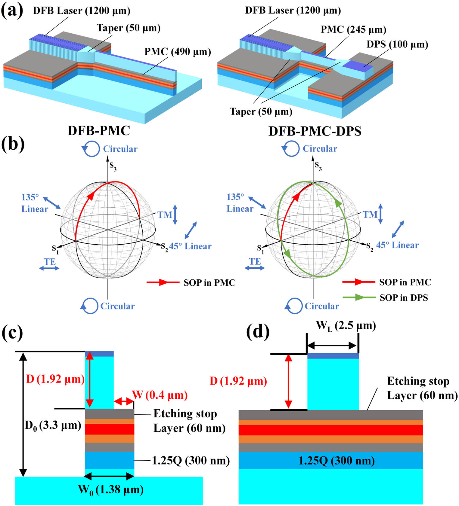
    Fig. 1. (a) Schematic of the monolithic DFB-PMC device (left) and DFB-PMC-DPS device (right); (b) SV propagates inside the DFB-PMC (left) and the DFB-PMC-DPS device (right); (c) cross-section structure of the PMC; (d) cross-section structure of the DPS.
    (a), (b) The fundamental eigenmodes in taper output (a) and PMC stepped-height ridge waveguide (b); (c) and (d) calculated maximum PCE (c), and corresponding Lπ (d) as a function of waveguide width (W0) and corner width (W) at an operating wavelength of 1550 nm.
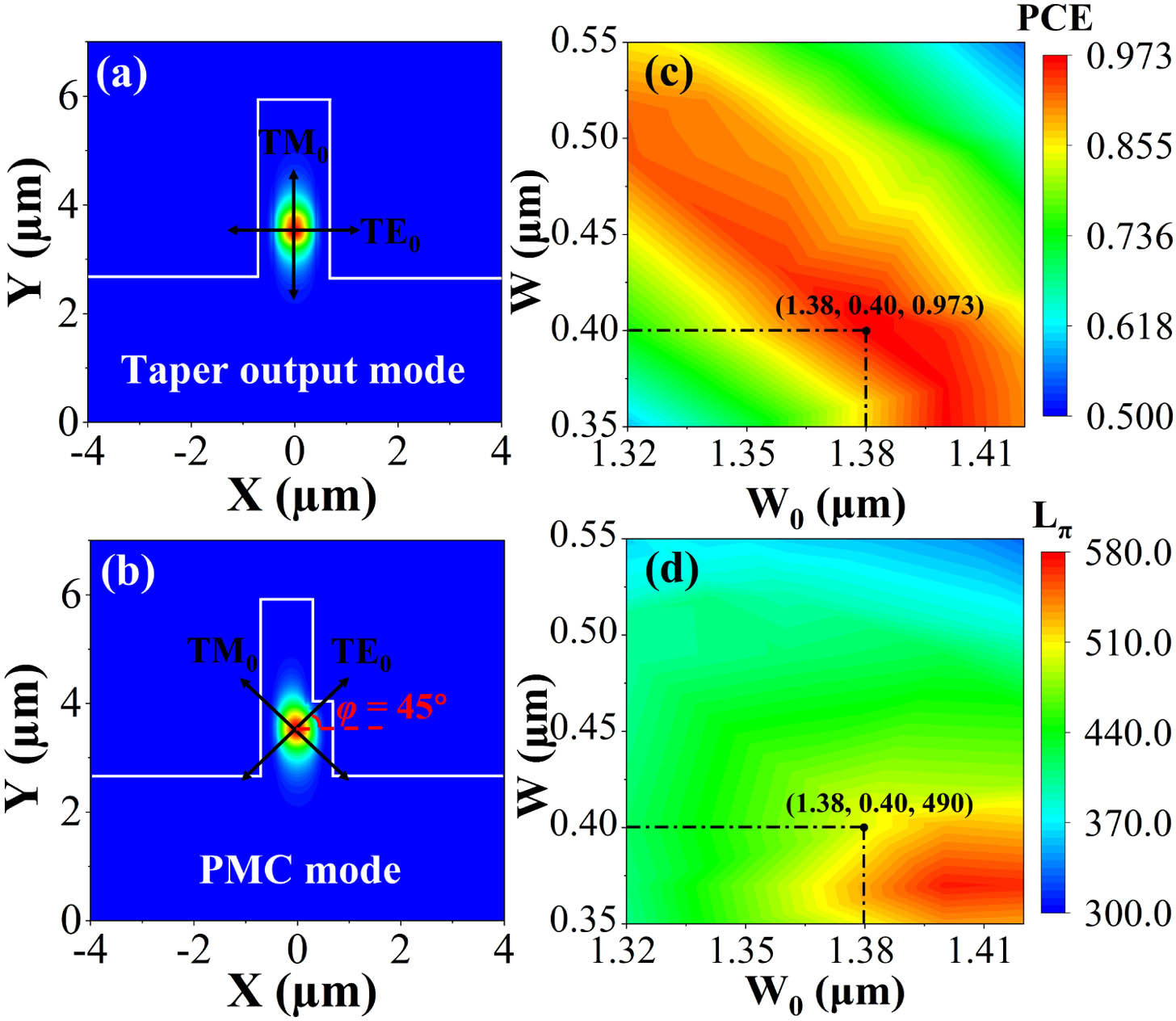
    Fig. 2. (a), (b) The fundamental eigenmodes in taper output (a) and PMC stepped-height ridge waveguide (b); (c) and (d) calculated maximum PCE (c), and corresponding Lπ (d) as a function of waveguide width (W0) and corner width (W) at an operating wavelength of 1550 nm.
    (a) Calculated TE and TM absorption coefficients in the DPS. (b) The difference of the effective refractive index changes between the TE and TM modes at different VDPS. (c) Phase-shifted angle as a function of VDPS at 1.557 μm operation wavelength.
    Fig. 3. (a) Calculated TE and TM absorption coefficients in the DPS. (b) The difference of the effective refractive index changes between the TE and TM modes at different VDPS. (c) Phase-shifted angle as a function of VDPS at 1.557 μm operation wavelength.
    (a)–(f) Fabrication procedures: (a) MOVPE epilayer growth, (b) EBL to define the laser and PMC first step waveguide, (c) ICP shallow etching, (d) EBL to define the second step waveguide of the PMC, (e) ICP deep etching, (f) HSQ elimination. (g) Workflow of monolithic DFB-PMC device fabrication. (h)–(j) SEM images after (h) the first shallow etch, (i) second step EBL using HSQ photoresist, (j) PMC deep etch and HSQ elimination.
    Fig. 4. (a)–(f) Fabrication procedures: (a) MOVPE epilayer growth, (b) EBL to define the laser and PMC first step waveguide, (c) ICP shallow etching, (d) EBL to define the second step waveguide of the PMC, (e) ICP deep etching, (f) HSQ elimination. (g) Workflow of monolithic DFB-PMC device fabrication. (h)–(j) SEM images after (h) the first shallow etch, (i) second step EBL using HSQ photoresist, (j) PMC deep etch and HSQ elimination.
    (a)–(c) SEM images of (a) the DFB laser with sidewall gratings, (b) output facet of the PMC, (c) DFB-PMC device. (d) and (e) Microscope pictures of the (d) DFB-PMC device and (e) DFB-PMC-DPS device.
    Fig. 5. (a)–(c) SEM images of (a) the DFB laser with sidewall gratings, (b) output facet of the PMC, (c) DFB-PMC device. (d) and (e) Microscope pictures of the (d) DFB-PMC device and (e) DFB-PMC-DPS device.
    (a)–(d) Measured optical spectra for the 1543 nm DFB-PMC device measured from DFB (a), (b) and PMC (c), (d) facets. (e)–(h) Optical spectra for the 1555 nm DFB-PMC device from DFB (e), (f) and PMC (g), (h) facets. (i)–(l) Optical spectra for the 1567 nm DFB-PMC device from DFB (i), (j) and PMC (k), (l) facets.
    Fig. 6. (a)–(d) Measured optical spectra for the 1543 nm DFB-PMC device measured from DFB (a), (b) and PMC (c), (d) facets. (e)–(h) Optical spectra for the 1555 nm DFB-PMC device from DFB (e), (f) and PMC (g), (h) facets. (i)–(l) Optical spectra for the 1567 nm DFB-PMC device from DFB (i), (j) and PMC (k), (l) facets.
    (a) Measured net modal gain as a function of the wavelength using the Haki–Paoli method, (b) optical spectrum at threshold current (48 mA) of a 800 μm length DFB LD with a π-phase shift section inserted at the center of the DFB LD cavity.
    Fig. 7. (a) Measured net modal gain as a function of the wavelength using the Haki–Paoli method, (b) optical spectrum at threshold current (48 mA) of a 800 μm length DFB LD with a π-phase shift section inserted at the center of the DFB LD cavity.
    Experimental setup for the SOP measurement for DFB-PMC and DFB-PMC-DPS devices.
    Fig. 8. Experimental setup for the SOP measurement for DFB-PMC and DFB-PMC-DPS devices.
    Measured SV at the PMC side for (a) 1543 nm, (b) 1555 nm, (c) 1568 nm wavelength DFB-PMC devices.
    Fig. 9. Measured SV at the PMC side for (a) 1543 nm, (b) 1555 nm, (c) 1568 nm wavelength DFB-PMC devices.
    Simulated and measured PCE versus DFB lasing wavelength.
    Fig. 10. Simulated and measured PCE versus DFB lasing wavelength.
    Measured optical spectrum from (a), (b) DFB LD rear facet and (c), (d) DPS section output facet.
    Fig. 11. Measured optical spectrum from (a), (b) DFB LD rear facet and (c), (d) DPS section output facet.
    (a) Measurement of SV at the DPS side as a function of IDFB with VDPS=0 V, (b) rotation of SV at the DPS output facet as a function of VDPS for DFB-PMC-DPS devices with IDFB=170 mA.
    Fig. 12. (a) Measurement of SV at the DPS side as a function of IDFB with VDPS=0  V, (b) rotation of SV at the DPS output facet as a function of VDPS for DFB-PMC-DPS devices with IDFB=170  mA.
    Comparison between the measured and simulated phase shift angles as a function of VDPS.
    Fig. 13. Comparison between the measured and simulated phase shift angles as a function of VDPS.
    (a) Calculated TE and TM absorption coefficient at VDPS=0 V and −3 V, respectively, and (b) value of ΔnTE−ΔnTM as a function of wavelength at different bias voltages for a DPS with a 100 nm blueshift using QWI.
    Fig. 14. (a) Calculated TE and TM absorption coefficient at VDPS=0  V and 3  V, respectively, and (b) value of ΔnTEΔnTM as a function of wavelength at different bias voltages for a DPS with a 100 nm blueshift using QWI.
    Calculated phase shift angle Δθ for a 900 μm long DPS with a 100 nm blueshift by QWI at an operating wavelength of 1.55 μm.
    Fig. 15. Calculated phase shift angle Δθ for a 900 μm long DPS with a 100 nm blueshift by QWI at an operating wavelength of 1.55 μm.
    Designed Bragg Grating Wavelength (nm)DFB Facet SMSR (dB)PMC Facet SMSR (dB)Measured Current (mA) and Wavelength Range (nm)ACWRC (nm/mA)
    1540278Current: 118–1700.0250
    Wavelength: 1542.9–1544.2
    15502912Current: 104–2200.0207
    Wavelength: 1554.2–1556.6
    15653820Current: 97–2110.0271
    Wavelength: 1566.3–1569.4
    Table 1. Measured Parameters of the Three DFB-PMC Devices with Different Designed Bragg Wavelengths
    Designed DFB Laser Wavelength (nm)Measured DFB Laser Wavelength (nm)Current Range (mA)Average PCEMAX PCE
    15401543.6–1544.2150–17093.0%94.3%
    15501554.9–1555.9140–19098.4%99.1%
    15651567.4–1568.7140–19089.8%90.5%
    Table 2. Measured PCE from the PMC Side of the DFB-PMC Devices
    Xiao Sun, Song Liang, Weiqing Cheng, Shengwei Ye, Yiming Sun, Yongguang Huang, Ruikang Zhang, Jichuan Xiong, Xuefeng Liu, John H. Marsh, Lianping Hou. Regrowth-free AlGaInAs MQW polarization controller integrated with a sidewall grating DFB laser[J]. Photonics Research, 2023, 11(4): 622
    Download Citation