
Jia-Cheng ZHU, Jian-Kang ZHOU, Wei-Min SHEN. Design of polarization-independent two-dimensional binary blazed grating[J]. Journal of Infrared and Millimeter Waves, 2020, 39(2): 149
- Journal of Infrared and Millimeter Waves
- Vol. 39, Issue 2, 149 (2020)
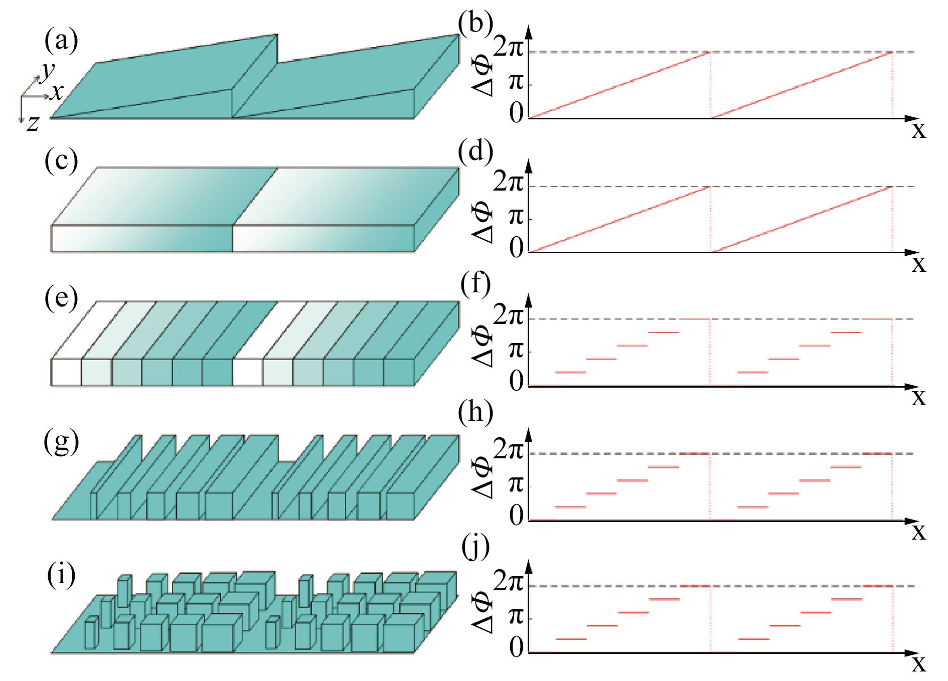
Fig. 1. Transition from a saw-tooth blazed grating to a binary blazed grating with similar optical function (a) Saw-tooth groove shape, (b)pPhase change of normal incident light transmitting through (a), (c) rectangular groove with continuously-changed refractive index, (d) phase change of (c), (e) rectangular groove with discretely-changed refractive index, (f) phase change of (e), (g) 1D binary groove shape, (h) phase change of (g), (i) 2D binary groove shape, (j) Phase change of (i)
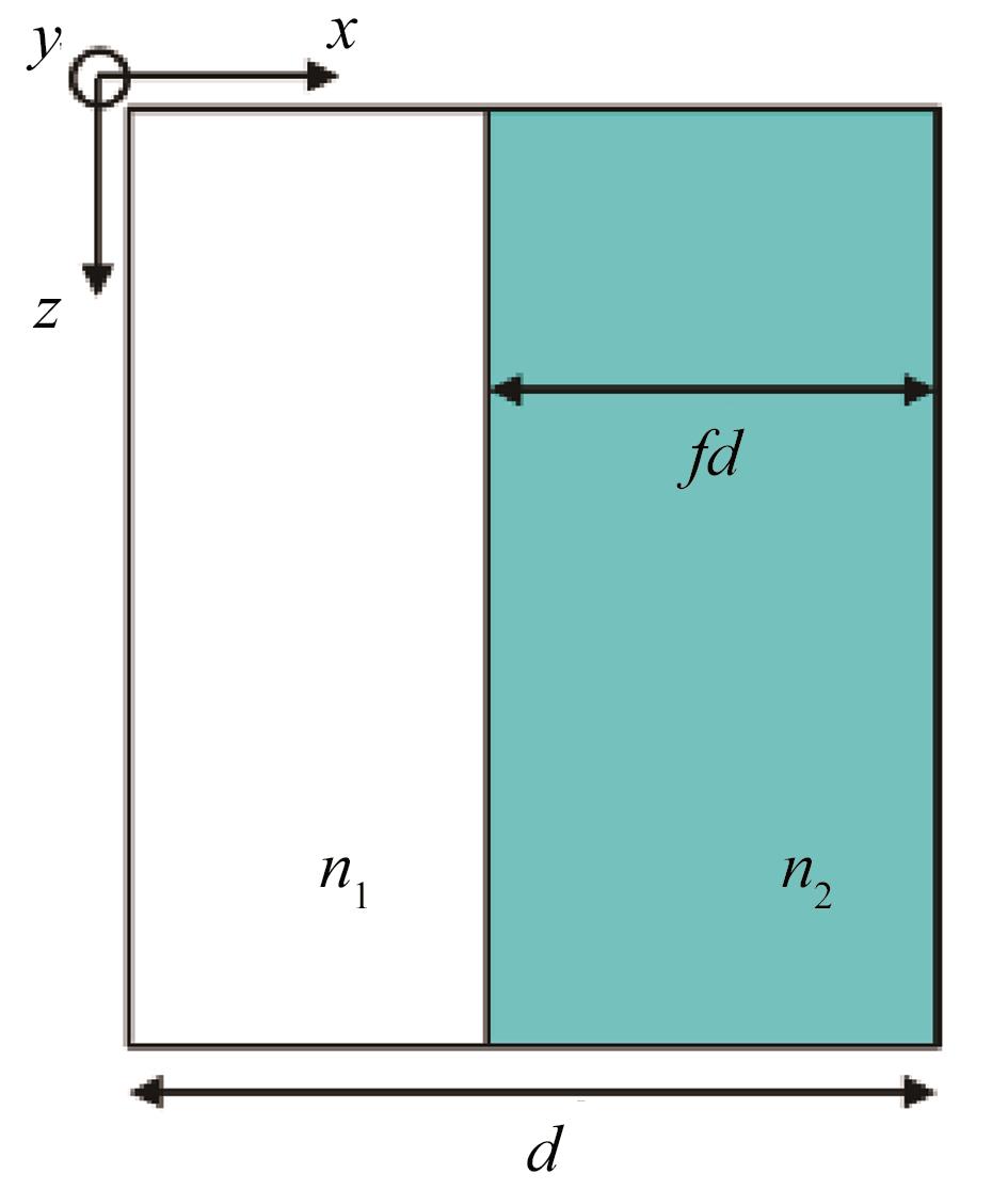
Fig. 2. Lateral view of sub-period in 1D binary blazed grating.
Fig. 3. Peak efficiencies of pure 1D binary blazed grating for different M
Fig. 4. Diffraction efficiency of the designed 1D binary blazed grating
Fig. 5. Top view of 2D binary blazed grating (a) Groove unit, (b) sub-period of grating groove
Fig. 6. Relationship between effective index of a 2D binary structure and its shape-factors, fx and fy , at a reference wavelength of 0.7 μm (a) n eTE, (b) n eTM
Fig. 7. Change of |n eTEn eTM| relative to shape-factors. The zero-value area (curve) corresponds to suitable shape-factors for n eTEn eTM, meaning non-birefringent for the 2D pillars with these shape-factors
Fig. 8. Dependence of diffraction efficiency at 0.7 μm with the groove depth h of the designed 2D binary blazed grating
Fig. 9. Groove structures of the designed 2D binary blazed grating
Fig. 10. Near field distributions of the designed 2D binary blazed grating under (a) TE-polarized, and (b) TM-polarized illuminations.
Fig. 11. Diffraction efficiency of the designed 2D binary blazed grating. The efficiencies of TE and TM polarizations over the wavelength range are both above 70%. The DOP is negligible at 0.7 μm and the maximum DOP is 2.6% at 0.8 μm
Fig. 12. Different locations of 2D pillars in sub-periods of a groove unit (a) at the top, (b) at the bottom, and (c) at random locations in each sub-period along y -axis and in the center along x -axis, (d) on the left side, (e) on the right side, and (f) at random locations in each sub-period along x -axis and in the center along y -axis
Fig. 13. Diffraction efficiencies and DOPs of the 2D binary blazed gratings with different pillar locations. The upper three curves refer to diffraction efficiencies of three gratings with different locations of 2D pillars along x -axis, and the lower three curves refer to their DOPs
|
Table 1. Fill-factor and effective index of each sub-period in the designed 1D binary blazed grating
|
Table 2. Shape-factor and effective index of each sub-period in the designed 2D binary blazed grating
| |||||||||||||||||||||||||||||||||||
Table 3. Main characteristics of six gratings with different pillar locations as shown in Fig. 12.

Set citation alerts for the article
Please enter your email address
© Copyright 2018-2021 | Chinese Laser Press. All Rights Reserved 沪ICP备15018463号-20