Abstract
In order to reduce imaging spectrometer’s polarization sensitivity and improve its quantitative measurement accuracy of target’s spectral radiance, a transmission polarization-independent two-dimensional binary blazed grating was proposed. It consists of periodical groove units in both orthogonal directions and there contains 7 sub-periods within one groove unit. Duty cycles of sub-periods are independent in two orthogonal directions, so that the effective index of both TE and TM polarizations can be modulated simultaneously, and the grating’s polarization property can be optimized. Through extending the effective medium theory to the two-dimensional pattern, a two-dimensional binary blazed grating with polarization-independent high efficiency on fused silica substrate was designed for wavelength range from 0.6 to 0.8 μm. The grating periods in two orthogonal directions are 3.3 1μm and 0.473 μm, respectively. Simulation results show that, for normal incident light, diffraction efficiencies of TE and TM polarizations at reference wavelength 0.7 μm are 78.4% and 78.3%, respectively. Within wavelength range from 0.6 to 0.8 μm, diffraction efficiencies of TE and TM polarizations are both above 70% and the degree of polarization is below 2.6%. Compared with one-dimensional binary blazed grating, the two-dimensional grating has the advantages of high diffraction efficiency, low degree of polarization and easier manufacture. It is expected to be used in grating-type imaging spectrometers.Introduction
Diffraction gratings are key elements of grating-type imaging spectrometers. Their diffraction efficiency and degree of polarization (DOP) directly affects the signal-to-noise ratio (SNR) and radiometric error of imaging spectrometers, respectively. When used in the field of quantitative hyperspectral remote sensing, imaging spectrometers are expected to be polarization-independent to ensure the measurement accuracy of target’s spectral radiance, since the light reflected by ground targets will be significantly polarized after being scattered by atmosphere [4].
Blazed gratings with saw-tooth grooves [5] can achieve high diffraction efficiency at a particular diffraction order, but such gratings are generally polarization-sensitive, and ideal saw-tooth grooves with small periodic structures are difficult to fabricate. Specially, saw-tooth blazed gratings can be imitated by the equivalent binary gratings which can be manufactured with the lithographic technologies such as laser direct writing [6] and electron-beam lithography [8]. A binary blazed grating consisting of one-dimensional (1D) or two-dimensional (2D) subwavelength structures can modulate the effective index within one grating groove to imitate a saw-tooth groove effectively.
Many researches have been done on binary blazed gratings. In the early 1990s, Stork [9] and Babin [10] designed binary subwavelength zero-order gratings used as anti-reflection layers with the effective medium theory. Haidner [11] and Nan [12] designed binary blazed gratings with the form-birefringence theory to decrease the manufacture difficulty of saw-tooth gratings with ideal size and profile, and high diffraction efficiency was achieved. In 2012, Wu et al. [13] presented a binary blazed grating based on silicon substrate, used as a high-reflectivity resonance filter. These works are focused on 1D binary gratings which can achieve high diffraction efficiencies but remain birefringent and polarization sensitive.
Differently, binary gratings with 2D structures can be optimized polarization independent. In 1992, Motamedi et al. [14] proposed a 2D binary grating based on silicon substrate to obtain polarization-independent transmittance. It was used as anti-reflection surface, not diffractive element. In 1998, Lalanne et al. [15] reported a 2D binary blazed grating for He-Ne laser, in which the TiO2 grating layer was deposited upon a glass substrate. Its diffraction efficiency was superior to that of saw-tooth blazed gratings, and the DOP was quite low at the operating wavelength. Recently, Fraunhofer IOF in Jena has reported a binary blazed grating for hyperspectral imagers[17] for the GAIA mission [18]. This grating is composed of 1D bars and 2D pillars, the 2D structures were designed to reduce the difficulty of manufacture. It has high efficiency but only works within a narrow spectral band of 847∼874 nm. Until now, there is no design method and report on polarization-independent binary blazed gratings used for imaging spectrometers. In order to further improve the measuring accuracy of grating-type imaging spectrometers, it is necessary to achieve blazed gratings with high diffraction efficiency and low DOP.
In the design concepts presented here, we are seeking increase in diffraction efficiency and decrease in DOP for a binary blazed grating with 2D structures. We first discuss the general method for designing a binary blazed grating with the effective medium theory [10,20] in Sect. 1. A 1D binary blazed grating is designed and its birefringence and polarization-sensitivity are proved. We then extend the effective medium theory to the 2D case in Sect. 2, and the expression of effective index for 2D subwavelength structure is derived. Method for designing a 2D binary blazed grating without birefringence is presented and its diffraction characteristics are analyzed. Sect. 3 presents comparisons between the designed 1D and 2D binary blazed gratings. Discussions about how pillar locations in sub-periods will influence diffraction characteristics are shown as well. Summary and conclusions are given in Sect. 4.
1 Theory
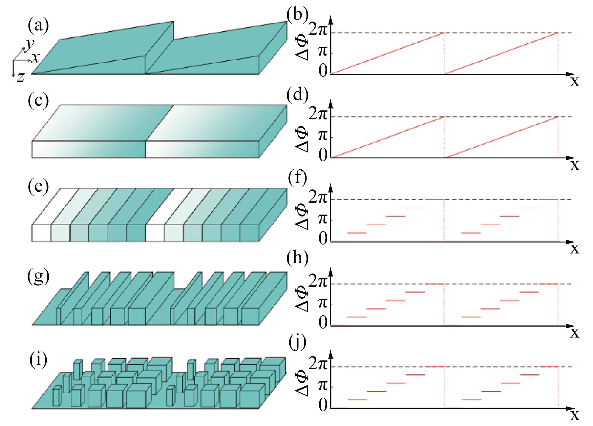
The transition from a saw-tooth blazed grating to a binary blazed grating is sketched in Fig. 1. Fig. 1(a) is the ideal saw-tooth groove shape. The phase change of the normal incident light through the groove is

Figure 1.Transition from a saw-tooth blazed grating to a binary blazed grating with similar optical function (a) Saw-tooth groove shape, (b)pPhase change of normal incident light transmitting through (a), (c) rectangular groove with continuously-changed refractive index, (d) phase change of (c), (e) rectangular groove with discretely-changed refractive index, (f) phase change of (e), (g) 1D binary groove shape, (h) phase change of (g), (i) 2D binary groove shape, (j) Phase change of (i)
where n2 is the refractive index of the grating substrate, n1 is the refractive index of air, h is the height of the grating groove, and λ is the wavelength. The blazed grating has a linear phase modulation for the incident light from 0 to 2π within one grating period, as shown in Fig. 2(b). This can be achieved by a saw-tooth groove in which h changes linearly and can also be realized by a rectangular groove whose refractive index n2 changes linearly, as shown in Fig. 1 (c). Its phase change shown in Fig. 2(d). The periodic arrangement of this structure is hard to achieve in recent manufacturing technology, thus a manufacturable approximate structure is needed. Concretely, as shown in Fig. 1(e), the grating groove is discretized into several sub-periods, and refractive index within each sub-period is uniform, satisfying
where M is the number of sub-periods and m is the ordinal of sub-period. The refractive index of different sub-periods varies linearly from n1 to n2. Such groove shape can provide discrete and linear phase change for the normal incident light from 0 to 2π, as shown in Fig. 1(f), imitating the continuous phase change in Fig. 1(b).Then, by means of the effective medium theory, a 1D binary groove shape approximate to Fig. 1(e) is available, as shown in Fig. 1(g). The effective index of each sub-period is a function of the local fill-factor and also depends on the polarization state of the light. Its phase change can be optimized to the same as Fig. 2(f) within one grating groove, as shown in Fig. 2(h). Through extending the effective medium theory to 2D pattern, the 2D binary blazed grating shown in Fig. 2(i) can be designed, its diffraction characteristics will be determined by materials and shapes of its pillars, detailedly discussed in Section 3.
Figure 2.Lateral view of sub-period in 1D binary blazed grating.
A sub-period of 1D binary blazed grating is sketched in Fig. 2. It has a width of d and a fill-factor of f, and ne is the effective index of this sub-period. According to the effective medium theory [10], to meet the continuous boundary conditions of electromagnetic fields, the effective indexes must obey the following equations,
where neTE and neTM are effective indexes of TE and TM polarization, respectively.
In this paper, a binary blazed grating based on fused silica substrate was designed for a fluorescence imaging spectrometer, which will measure the vegetation fluorescence in the spectral range between 0.6 and 0.8 μm, and its spectral resolution is 2nm. The grating was designed for normal incidence and blazed in the first diffraction order, and its grating constant is 3.31μm. We first considered pure 1D structures to design this grating. Taking manufactural feasibility and equivalent accuracy into consideration, number of sub-periods within a grating period was optimized. We respectively discretized one grating period into 3~11 sub-periods and solved their groove shapes by using Eqs. 2-3. We then simulated the diffraction of these gratings with different numbers of sub-periods and calculated their diffraction efficiencies by finite element method. Their peak efficiencies of TE polarization are shown in Fig. 3.
Figure 3.Peak efficiencies of pure 1D binary blazed grating for different M
As shown in Fig. 3, peak efficiency of the binary blazed grating increases as the number of sub-periods increases. When M is less than 6, the peak efficiency increases rapidly and when M is greater than 8, the peak efficiency increases slowly and tends to be stable. This is because the more sub-periods the grating groove contains, the higher accuracy of the binary blazed grating equivalent to a saw-tooth blazed grating. When M reaches a certain number, the equivalent accuracy is high enough, and more sub-periods will not increase its peak efficiency anymore. On the other hand, the smallest bar width will decrease as M increases, which will result in more difficulty of fabrication process. Having these in mind, we designed a 1D binary blazed grating containing 7 sub-periods within one grating groove. Its target refractive index and the fill-factor of each sub-period were solved by Eqs. 2-3, respectively. Table 1 gives the fill-factors, neTE, neTM, and the target refractive index of the designed 1D grating.
| m | f | neTE | neTM | Target |
|---|
| 1 | 0.000 | 1.000 | 1.000 | 1.000 |
| 2 | 0.126 | 1.083 | 1.040 | 1.077 |
| 3 | 0.248 | 1.169 | 1.091 | 1.153 |
| 4 | 0.386 | 1.251 | 1.164 | 1.230 |
| 5 | 0.558 | 1.324 | 1.255 | 1.307 |
| 6 | 0.775 | 1.391 | 1.349 | 1.383 |
| 7 | 1.000 | 1.460 | 1.460 | 1.460 |
Table 1. Fill-factor and effective index of each sub-period in the designed 1D binary blazed grating
From Table 1, neTE is not equal to neTM in most situations, since shape of the subwavelength 1D structure can be adjusted in only one direction with a single variate f, and neTE is not equal to neTM when the incident light meets the continuous boundary conditions for TE and TM polarization simultaneously, i.e. Eqs. 3-4. This means that the designed 1D binary blazed grating is mightily birefringent. Figure 4 shows its diffraction efficiencies. The average diffraction efficiency is below 70%, and the DOP is above 5% over the spectral range. The DOP is defined as
Figure 4.Diffraction efficiency of the designed 1D binary blazed grating
where ηTE and ηTM are diffraction efficiency of TE and TM polarization, respectively. Depth of the groove has been optimized for higher peak diffraction efficiency in the spectral band, and the optimized depth is h=1.3 µm. As can be calculated from Table 1, the smallest lateral bar width is 59.6 nm. Together with the required depth this leads to an aspect ratio (structure height/width) of approximately 21.8, which is still extremely difficult to realize experimentally.
2 Design of 2D binary blazed grating
Principle of 2D binary blazed grating equivalent to a saw-tooth blazed grating is similar to that of the 1D case as discussed in section 2. Different from the 1D case, it consists of 2D groove units periodically arranged in two orthogonal directions, and its groove unit containing 7 sub-periods is shown in Fig. 5(a). This groove unit can approximate to the structure in Fig. 1(c) through adjusting the shape of 2D pillars in each sub-period and optimizing their effective indexes for linear distribution. To avoid extra energy loss and stray light, the additional periodic structure along y-axis needs to have a subwavelength periodicity to prevent diffraction. In this paper, the grating period along y-axis is dy=0.473 μm, and the width of sub-period along x-axis is dx=0.4729 μm. Sketch of a sub-period is shown in Fig. 5(b). Its dielectric pillar is in the center of the sub-period. Its effective index of TE and TM polarization, neTE and neTM, can be respectively optimized by adjusting shape-factors fx along x-axis and fy along y-axis. This provides the possibility of designing a non-birefringent 2D binary blazed grating, which means neTE = neTM for each sub-period with preferred shape-factors.
Figure 5.Top view of 2D binary blazed grating (a) Groove unit, (b) sub-period of grating groove
For 2D binary structures, whether the incident light is TE or TM polarized, the electric and magnetic field components are respectively perpendicular to its two lateral boundaries. Having this in mind, we extended the effective medium theory to the 2D case by means of the theoretical analysis in Section 2. When the incident light is TE polarized, its electric vector E is parallel to the yoz plane. With the boundary condition for TE polarization, we can first obtain the effective index nxTE of a 1D binary structure with a fill-factor of fx. For the boundary parallel to the xoz plane, this incident light can be seen as TM polarized. We then utilized the boundary condition for TM polarization, obtaining the effective index neTE of this 2D binary structurewith shape-factors of fx and fy.
Similarly, if the incident light is TM polarized, the magnetic vector H is parallel to the yoz plane. With the boundary condition for TM polarization, we can first obtain the effective index nxTM of a 1D binary structure with a fill-factor of fx. Then, utilizing the boundary condition for TE polarization, the effective index neTM of TM polarization can be solved. With the above discussions, we combined Eqs. 3-4 to find out that neTE and neTM of a 2D binary structure should meet
Different from the 1D case, shape of the 2D binary structures can be optimized with the boundary conditions for TE and TM polarizations simultaneously, and the effective indexes of both polarizations will be taken into consideration during the design process. This makes it more flexible in design than the 1D structure. Relationship between the effective index of a 2D binary structure and its shape-factors can be numerically solved by Eqs. 6-7. The relationships at a reference wavelength of 0.7 μm are given in Fig. 6, based on fused silica substrate. As shown in these figures, when fx and fy are both 0, effective indexes of TE and TM polarizations are both 1. When fx and fy are both 1, effective indexes of TE and TM polarizations are both 1.46 (refraction index of fused silica). Any effective index between 1 and 1.46 can be obtained through adjusting fxand fy. Although effective indexes of TE and TM polarizations have the same trend with fx and fy, there is a clear difference between Fig. 6(a) and (b), which means that neTE and neTM are not always equal at the same shape-factors. In order to visually present their difference, we show a map of |neTE- neTM| in Fig. 7. The boundary of fx=1 or fy=1 in this figure corresponds to the 1D case, where |neTE- neTM| changes significantly. This proves the birefringence of 1D binary structure as well. There is an obvious zero-value area (curve) in Fig. 7, which corresponds to suitable shape-factors for neTE= neTM, meaning non-birefringent for the 2D pillars with these shape-factors.
Figure 6.Relationship between effective index of a 2D binary structure and its shape-factors, fx and fy, at a reference wavelength of 0.7 μm (a) neTE, (b) neTM
Figure 7.Change of |neTE- neTM| relative to shape-factors. The zero-value area (curve) corresponds to suitable shape-factors for neTE= neTM, meaning non-birefringent for the 2D pillars with these shape-factors
Based on the above discussions and analyses, we have designed a polarization-independent 2D binary blazed grating for normal incident light with the same specifications as the 1D grating presented in Sec. 1. Table 2 gives its shape-factors and the effective index of each sub-period, calculated by Eqs. 6-7. Its 2D pillars are in the center of each sub-period. Their shape-factors, fx and fy, were optimized for meeting neTE= neTM, and they are different except when m=1 or 7. Effective indexes are consistent well with the target refractive indexes because of the high equivalent precision of the 2D structure with two adjustable variates. Diffraction characteristics of this grating were simulated by the finite element analysis software COMSOL. Its groove depth was optimized for reaching the highest diffraction efficiency. We swept its groove depth in the software to obtain the dependence of average diffraction efficiency at 0.7 μm with its groove depth h. The result is shown in Fig. 8. The optimized groove depth is at about h=1.33 µm, and groove structures of this 2D binary blazed grating are shown in Fig. 9. This grating contains 1D bars and 2D pillars, for the last sub-period of its groove unit is full of dielectric. The lateral width of the smallest structure calculated from Table 2 is 0.142 μm. Thus, the highest aspect ratio is reduced from 21.8 in the 1D case to only 9.4 in the 2D case leading to much easier to fabrication process. Figs. 10(a-b) show the simulated near field distributions in this 2D binary blazed grating. The transmitted TE- and TM-polarized wavefronts are clearly deflected by the same angle, exhibiting the polarization-independent phase control. The simulation results show that, at the reference wavelength 0.7μm, diffraction efficiencies of TE and TM polarizations are 78.4% and 78.3%, respectively. Its DOP is negligible at this wavelength, only 0.1%. As shown in Fig. 11, diffraction efficiencies of TE and TM polarizations over the wavelength range of 0.6∼0.8 μm are both above 70%, and the maximum DOP is 2.6% at 0.8 μm. It has higher efficiency and lower DOP than the designed 1D grating.
| m | fx | fy | neTE | neTM | Target |
|---|
| 1 | 0.000 | 0.000 | 1.000 | 1.000 | 1.000 |
| 2 | 0.502 | 0.301 | 1.077 | 1.077 | 1.077 |
| 3 | 0.595 | 0.497 | 1.153 | 1.152 | 1.153 |
| 4 | 0.712 | 0.651 | 1.230 | 1.231 | 1.230 |
| 5 | 0.822 | 0.795 | 1.307 | 1.307 | 1.307 |
| 6 | 0.921 | 0.918 | 1.383 | 1.383 | 1.383 |
| 7 | 1.000 | 1.000 | 1.460 | 1.460 | 1.460 |
Table 2. Shape-factor and effective index of each sub-period in the designed 2D binary blazed grating
Figure 8.Dependence of diffraction efficiency at 0.7 μm with the groove depth h of the designed 2D binary blazed grating
Figure 9.Groove structures of the designed 2D binary blazed grating
Figure 10.Near field distributions of the designed 2D binary blazed grating under (a) TE-polarized, and (b) TM-polarized illuminations.
Figure 11.Diffraction efficiency of the designed 2D binary blazed grating. The efficiencies of TE and TM polarizations over the wavelength range are both above 70%. The DOP is negligible at 0.7 μm and the maximum DOP is 2.6% at 0.8 μm
In the 2D binary blazed grating designed above, its pillars are in the center of each sub-periods. According to the effective medium theory, there is no relationship between the effective index of a sub-period and the location of its dielectric pillar, but the pillar locations can have influence on diffraction characteristics of this 2D binary grating. Six groove units with different pillar locations are shown in Fig. 12. In these figures, (a) and (b) respectively shows two limiting locations and (c) shows random locations in the y direction. While (d) and (e) respectively shows two limiting locations and (e) shows random locations in the x direction. To demonstrate how pillar locations will influence the diffraction efficiency of 2D binary blazed grating, we simulated the diffraction characteristics of six gratings with the same shape factors in Table 2 but different pillar locations in Fig. 12. By optimization and simulation, main characteristics of these gratings are given in Table 3, including the peak diffraction efficiency, DOP at 0.7 μm, the maximum DOP in the wavelength range of 0.6∼0.8 μm, and the optimized groove depth h.
Figure 12.Different locations of 2D pillars in sub-periods of a groove unit (a) at the top, (b) at the bottom, and (c) at random locations in each sub-period along y-axis and in the center along x-axis, (d) on the left side, (e) on the right side, and (f) at random locations in each sub-period along x-axis and in the center along y-axis
| Locatios | Peak efficieny | DOP@ 0.7 μm | Max DOP | h/μm |
|---|
| (f) | Floating in a range between data of (d) and (e) |
| (a) | 78.4% | 0.1% | 2.6% | 1.33 |
| (b) | 78.4% | 0.1% | 2.6% | 1.33 |
| (c) | 78.3% | 0.1% | 2.5% | 1.33 |
| (d) | 79.5% | 0.1% | 4.2% | 1.45 |
| (e) | 73.2% | 0.2% | 2.2% | 1.19 |
Table 3. Main characteristics of six gratings with different pillar locations as shown in Fig. 12.
From data in Table 3, we found out that pillar locations in the y direction have negligible influence on diffraction characteristics, for diffraction efficiencies and DOP of gratings containing groove units (a), (b) and (c) are almost equal. These data are also equal to those of the designed 2D grating with pillars located in the center of its sub-periods. Conversely, gratings containing groove units (d), (e) and (f) show different characteristics. This means that pillar locations in the x direction have significant influence on diffraction characteristics and groove depth as well. The grating with groove unit (d) shows higher efficiency, higher DOP, and larger h than the designed grating shown in Fig. 9, while (e) shows lower efficiency, lower DOP, and smaller h. The simulation results also show that, if pillars have random locations in each sub-period, the grating’s peak efficiency will vary between 73.2% and 79.5%, and its maximum DOP may be in a range between 2.2% and 4.2%.
Moreover, we compared three 2D gratings with different pillar locations as shown in Fig. 5(a), Fig. 12(d-e), for their average diffraction efficiencies and DOPs. Figure 13 gives their diffraction efficiencies and DOPs for normal incident light. From this figure, the grating with pillar locations on the left side in each sub-period has the highest diffraction efficiency and the highest DOP as well. As pillars move to the right side, its diffraction efficiency decreases as well as its DOP. When pillars are located in the center of sub-periods, its diffraction efficiency remains high, only a small amount lower than the case with pillars on the left side. Its DOP is greatly reduced and arrives at the same level as the case with pillars on the right side. This means that it can reach a balance between high efficiency and low DOP.
Figure 13.Diffraction efficiencies and DOPs of the 2D binary blazed gratings with different pillar locations. The upper three curves refer to diffraction efficiencies of three gratings with different locations of 2D pillars along x-axis, and the lower three curves refer to their DOPs
3 Comparisons and discussions
In this paper, the 1D binary blazed grating designed utilizing the boundary condition for TE polarization is birefringent. Phase change of the incident light with different polarizations transmitting through this grating will be significantly different, which causes polarization-sensitive diffraction. In contrast, the 2D binary blazed grating was designed non-birefringent with the consideration of boundary conditions for TE and TM polarizations, in which case its effective indexes for different polarizations can be modulated simultaneously. Therefore, the 2D binary blazed grating can be optimized polarization-independent at the reference wavelength. Meanwhile, 2D binary blazed grating is more flexible in design than 1D binary blazed grating, which makes that the effective index of 2D binary structure matches the target refractive index much better. Thus, it deserves higher diffraction efficiency. Moreover, the approach of using 2D pillars instead of 1D bars leads to a considerably larger lateral width, which greatly relaxes the demands on the fabrication process.
In the 2D binary blazed grating, locations of dielectric pillars in the y direction have negligible influence on diffraction characteristics. This is because the subwavelength periodic structures in the y direction make the grating layer homogeneous along y-axis no matter where the pillar is in each sub-period in this direction. Differently, pillar locations in the x direction have significant influence on the grating’s diffraction characteristics and groove depth. The 2D grating with pillars on the left side of each sub-period has the highest diffraction efficiency, DOP and groove depth. These characteristics will be decreasing as pillars moving to the right side of each sub-period. Through simulation, when pillars are in the center of each sub-period, the grating will show high diffraction efficiency and low DOP and appropriate groove depth, which is a preferred solution for practical applications.
4 Conclusions
A transmission polarization-independent 2D binary blazed grating for imaging spectrometer was proposed in this paper. We provide detailed information on the design method applying effective medium theory on the 1D and extension on the 2D case. A 2D binary blazed grating with periods of 3.31μm along x-axis and 0.473μm along y-axis was optimized and analyzed. Results show that, this grating is polarization-independent at the reference wavelength, and the DOP remains low over the wavelength range of 0.6∼0.8 μm. We discussed the pillar locations of this 2D grating and pointed that pillar locations in the x direction have influence on its diffraction efficiency and DOP. The 2D binary blazed grating can reach high efficiency and low DOP when its dielectric pillars are located in the center of each sub-period. Compared to the 1D grating, the 2D design has higher diffraction efficiency and lower DOP, and higher feasibility for manufacture. It is a good solution approach for designing polarization-optimized imaging spectrometers, and it has broad application prospects in the field of quantitative hyperspectral remote sensing or in other spectral detection fields requesting high accuracy and sensitivity.
References
[1] Z Sekera. Light scattering in the atmosphere and the polarization of sky light. J. Opt. Soc. Am, 47, 484-490(1957).
[2] V C Vanderbilt, L Grant. Plant canopy specular reflectance model. IEEE Trans. Geosci. Remote Sensing, 23, 722-730(1985).
[3] F M Breon, D Tanre, P Lecomte. Polarized reflectance of bare soils and vegetation measurements and models. IEEE Trans. Geosci. Remote Sensing, 33, 487-499(1995).
[4] F Nadal, F M Breon. Parameterization of surface polarized reflectance derived from POLDER spaceborne measurements. IEEE Trans. Geosci. Remote Sensing, 37, 1709-1718(1999).
[5] P Mouroulis, D W Wilson, P D Maker. Convex grating types for concentric imaging spectrometers. Appl. Opt, 37, 7200-8(1998).
[6] K C Vishnubhatla, S V Rao, R S S Kumar. Femtosecond laser direct writing of gratings and waveguides in high quantum efficiency erbium-doped Baccarat glass. : Appl. Phys, 42, 205106(2009).
[7] T Glaser, S Schroter, R Pohlmann. High-efficiency binary phase-transmission-grating using e-beam lithography. . Mod. Opt, 45, 1487-1494(1998).
[8] U D Zeitner, M Oliva, F Fuchs. High performance diffraction gratings made by e-beam lithography. Appl. Phy. A, 109, 789-796(2012).
[9] W Stork, N Streibl, H Haidner. Artificial distributed-index media fabricated by zero-order gratings. Opt. Lett, 16, 1921-1923(1991).
[10] S V Babin, J T Sheridan. Artificial index surface relief diffraction optical elements. Proc. SPIE, 1751, 202-213(1993).
[11] H Haidner, J T Sheridan, N Streibl. Design of a blazed grating consisting of metallic subwavelength binary grooves. Opt. Commun, 19, 5-10(1993).
[12] N Lu, D Kuang, G Mu. Design of transmission blazed binary gratings for optical limiting with the form-birefringence theory. Appl. Opt, 47, 3743-3750(2008).
[13] D Wu, X Sui, J Yang. Binary blazed grating-based polarization-independent filter on silicon. Front. Opto, 5, 78-81(2012).
[14] M E Motamedi, W H Southwell, W J Gunning. Antireflection surfaces in silicon using binary optics technology. Appl. Opt, 31, 4371-4376(1992).
[15] P Lalanne, S Astilean, P Chavel. Blazed binary subwavelength gratings with efficiencies larger than those of conventional echelette gratings. Opt. Lett, 23, 1081-1083(1998).
[16] U D Zeitner, D Michaelis, E B Kley. High performance gratings for space applications. Proc. SPIE, 2010 7716, 77161K.
[17] U D Zeitner, F Fuchs, E B Kley. Proc. SPIE, 8450, 84502Z(2012).
[18] J. H. J. de Bruijne. Science performance of Gaia, ESA's space-astrometry mission. Astrophys. Space Sci, 341, 31-41(2012).
[19] C C Tuck. Effective medium theory: principles and applications(2016).
[20] 20MariaA V, DomenicoD C, “Effective medium theories,” in Fundamentals and Applications of Nanophotonics[M]. Cambridge: Woodhead Publishing, 2016.