
Chaoqun Xu, Congfu Fang, Zhen Yan. Design and Experimental Study of Double-Pattern Nonuniform Coupling Fixed-Abrasive Pads[J]. Acta Optica Sinica, 2020, 40(8): 0824001
- Acta Optica Sinica
- Vol. 40, Issue 8, 0824001 (2020)
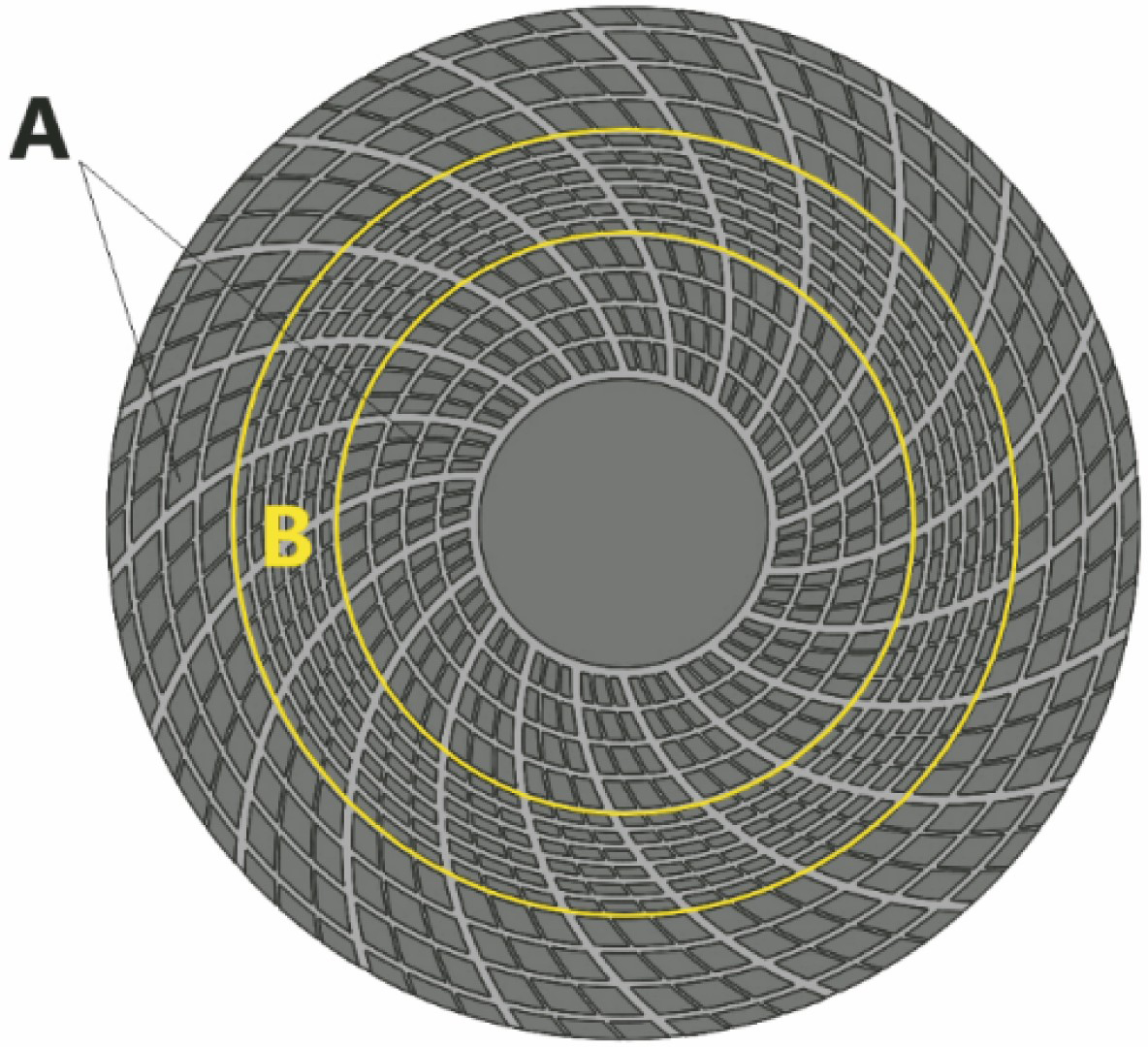
Fig. 1. Schematic diagram of DPP
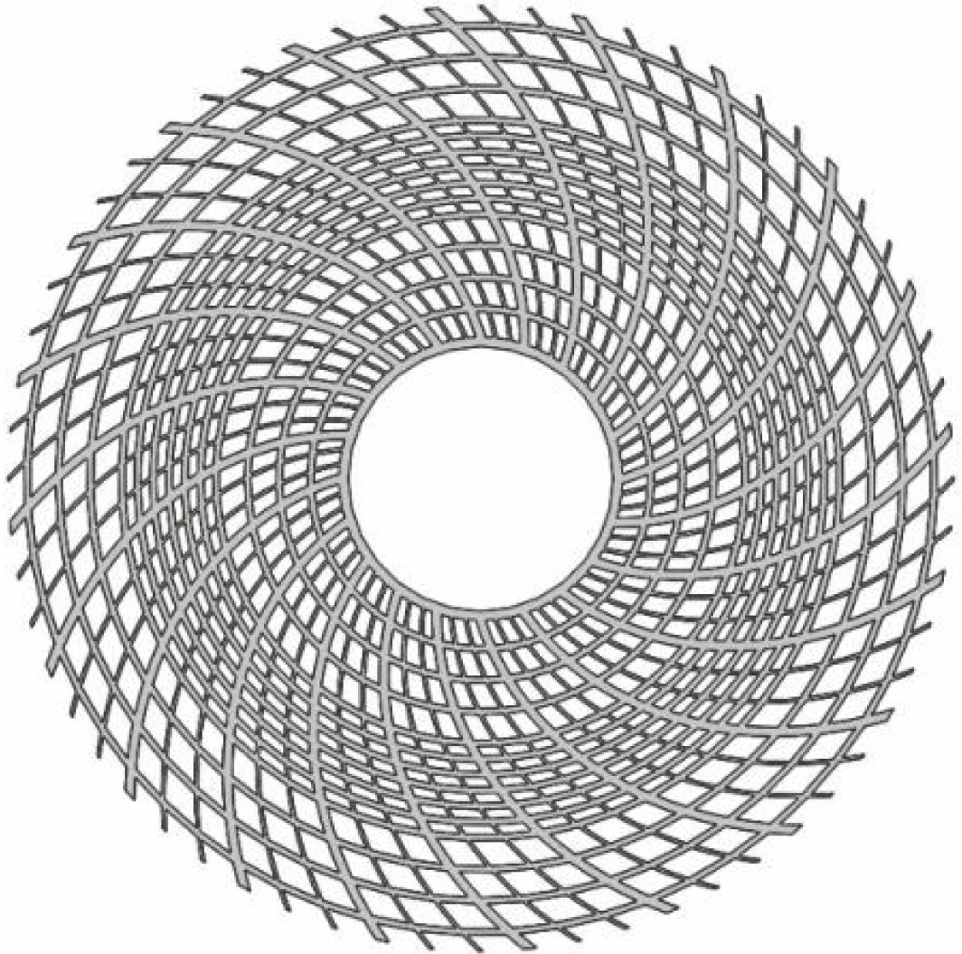
Fig. 2. Mould of DPP
Fig. 3. Preparation process. (a) Basic plate; (b) basic plate with non-abrasive layer; (c) adding abrasive layer and putting it into the mold; (d) demoulding forming
Fig. 4. Two test pads. (a) DPP; (b) GGP
Fig. 5. Morphologies of the workpiece processed by two kinds of pads. (a) Surface morphology of the workpiece processed by GGP; (b) surface morphology of the workpiece processed by GGP
Fig. 6. Extraction of surface defects on the workpiece. (a) Original morphology of workpiece; (b) morphology of workpiece after defect extraction
Fig. 7. Surface roughness of sapphire substrate polished by different pads. (a) Influence of rotational speed ratio on surface roughness; (b) influence of pressure on surface roughness
Fig. 8. PV of sapphire substrate polished by different pads. (a) Effect of rotational speed ratio on PV; (b) effect of pressure on PV
Fig. 9. Material removal under different polishing parameters. (a) Effect of rotational speed ratio on material removal rate; (b) effect of pressure on material removal rate
Fig. 10. Removal thickness distribution of GGP and DPP. (a) Removal thickness distribution of GGP; (b) removal thickness distribution of DPP
Fig. 11. Surface morphologies of the two pads. (a) Surface morphologies of GGP; (b) surface morphologies of DPP
Fig. 12. Morphology of the FAP. (A) Original morphology of the FAP; (b) extraction of debris from the FAP
Fig. 13. Schematic diagram of abrasive debris flow in two kinds of groove plates. (a) Schematic diagram of abrasive debris flow in GPP; (b) schematic diagram of abrasive flow in DPP
| ||||||||||||||||||
Table 1. Experimental parameters

Set citation alerts for the article
Please enter your email address
© Copyright 2018-2021 | Chinese Laser Press. All Rights Reserved 沪ICP备15018463号-20