Abstract
With the recent development of the metasurface, generating an optical vortex in optical far or near fields is realized in various ways. However, to generate vortices in both the near and far fields simultaneously is still a challenge, which has great potential in the future compact and versatile photonic system. Here, a bi-channel optical vortex generator in both the near and far fields is proposed and demonstrated within a single metasurface, where the surface plasmon vortex and the far-field optical vortex can be simultaneously generated under circularly polarized light. The ability of generating vortices with arbitrary topological charges is experimentally demonstrated, which agrees well with simulations. This approach provides great freedom to integrate different vortex generators in a single device, and offers new opportunities for integrated optical communications, trapping, and other related fields.
1. INTRODUCTION
Light beams that have a helical phase front and possess orbital angular momentum (OAM) are called optical vortex beams or OAM light. Different from the ordinary circularly polarized beam with spin angular momentum (the sign represents left or right circular polarization), the vortex beam can carry arbitrary OAM with a value of per photon [1,2], where is the topological charge value. And because of the helical phase front, a phase singularity appears at the center of the beam and causes a point of zero intensity. With these unique properties, vortex beams have revealed potential applications in broadband optical communications [3–5], super-resolution imaging [6,7], optical trapping [8–11], and quantum information technology [12,13]. To fully utilize the outstanding characteristics of vortex beams, it is highly desired to design and fabricate multifunctional vortex generators that have small size for the demand of minimization and integration of modern photonics.
In recent years, flat optics based on the metasurface has attracted great interest because of the flexibility of manipulating the phase, polarization, and amplitude of light at the subwavelength scale [14–18]. With the Pancharatnam–Berry phase principle, which is also known as the geometric phase, the carefully arranged subwavelength artificial structures can tailor the phase distribution pixel by pixel on an ultra-thin metasurface, which has shown the versatile ability to realize a wide range of applications for far-field light and near-field surface plasmon polaritons (SPPs), including unidirectional SPPs launching [15], anomalous refraction [14,19,20], metalens [21–26], and holograms [27–30]. An important application of the metasurface is to generate vortex beams, and different kinds of vortex generators based on metasurfaces have been proposed for far-field scattered light or near-field SPPs [18,31–37], such as generating of multiple vortices [33,34] and surface plasmon (SP) vortex [31,32,38]. However, the bridging role of the plasmonic metasurface between the near field and far field, which results from its unique ability of controlling near-field SPPs as well as far-field scattered light, has barely been exploited. There is an increasing demand for integration of the vortex generator with other photonic systems, such as light emitters and optical fibers [39–42], which is a key requirement for future versatile communication and information technology based on OAM light. Because plasmonic metasurfaces have the ability to support controlling of near-field SPPs and far-field scattered light, the vortex generator based on the plasmonic metasurface that can work at both near and far fields is a promising candidate to OAM source for future integration of plasmonic circuits and other photonic systems.
2. DESIGN AND RESULTS
In this work, we propose a design for a bi-channel optical vortex generator that can generate vortices with arbitrary configuration of topological charges in both the near and far fields using a single metasurface structure. By combining the spatially variant geometric phases of meta-atoms in both the near and far fields, the proposed metasurface can tailor the phase distribution to satisfy the OAM light with a designed topological charge for both near-field SPPs and far-field scattered light. Nanoslits that perforated in Au film were used to constitute this metasurface. Scanning near-field optical microscopy (SNOM) and far-field measurements were implemented to demonstrate this bi-channel near- and far-field vortex generator (NFVG). The proposed vortex generator can be designed to generate vortices with arbitrary topological charges in both near and far fields, which provides great potential for applications of OAM light in future integrated plasmonics and photonics.
Sign up for Photonics Research TOC. Get the latest issue of Photonics Research delivered right to you!Sign up now
A. Bi-Channel Near- and Far-Field Vortex Generator Design
Figure 1(a) shows the schematic of the designed metasurface for an integrated bi-channel near- and far-field optical vortex generator. The building blocks of this NFVG are nanoslits that perforated in Au film, which is shown in Fig. 1(b). The constitutive nanoslit has a width of 80 nm and a length of 250 nm, and the height of 120 nm equals the thickness of the Au film. When the incident light illuminates from the glass side, the nanoslit simultaneously stimulates SPPs in the near field that propagates along the metallic surface, and scatters as the incident light into the far field. Therefore, in this work, the SPP field and scattered light field are also called the near field and far field, respectively. In particular, for circular polarization (CP) incidence, the nanoslit generates SPPs with local geometric phase in the near field [15,43], and simultaneously scatters light with geometric phase of the cross-polarized light in the far field [17,26], where represents the spin state of incident light, for right-circular polarization (RCP) , and left-circular polarization (LCP) . is the orientation angle of the nanoslit relative to the axis as shown in Fig. 1(c).
Here, we first consider a metasurface structure that can generate an SP vortex with OAM . Assuming the incident light is circularly polarized, SPPs excited by different nanoslits interfere constructively with the spiral phase profile of . Then, by using the near-field geometric phase, the phase distribution satisfies the following equation: where is the SPP wave vector given by and is the wavelength of SPPs. and are the distance from a nanoslit to the center point and the azimuthal angle of the nanoslit relative to the axis, respectively. is an antiphase term with value 0 or dependent on the relative position and orientation of the nanoslit located at point to the center point [43]. is an integer and is a constant value. On the other hand, we consider a focused vortex beam in the far field. When the structure can generate a vortex light with OAM in the far field, with the geometric phase of far-field scattered light, the equation of phase distribution can be written as where is the wave vector of light in free space given by and is the wavelength of incident light. is the designed focal length of the far-field focused vortex. is an integer and is a constant value. In order to integrate the near-field SP vortex and far-field optical vortex generators in a single metasurface structure, Eqs. (1) and (2) should be satisfied simultaneously. By combining these two phase distribution equations and eliminating the orientation angle , the position that satisfied both Eqs. (1) and (2) can be obtained as Here, , which is an integer. When the design parameters (mainly including , , , and wavelength) are given, Eq. (3) can determine the position (, ) for eligible nanoslits. Then, the orientation angle of the nanoslits array can be obtained from Eq. (2) with the position (, ), which should also fulfill Eq. (1). As a result, the designed NFVG with near-field OAM topological charge and far-field OAM topological charge can be determined by the geometrical parameters of eligible nanoslits. It is worth noting that the orbital angular momentum conservation law is not required between the near- and far-field vortices, which is because the far-field vortex is not a result of the near to far propagation of the near-field vortex. In fact, the near-field vortex is an evanescent field, which is bound electromagnetic waves propagating at the metal surface with exponential field decay normal to the surface and cannot propagate to the far field. Therefore, the near- and far-field vortices are independent, so that our method can be applied flexibly for different topological charge configurations of both vortices.
To examine the feasibility of our proposed idea, an NFVG for the near-field vortex with the topological charge and far-field focused vortex with the topological charge under an LCP incident beam at 671 nm was designed. The focal length for the far-field focused vortex is 20 μm. Figure 2(a) shows the profile of the designed metasurface that satisfies Eqs. (1) and (2) when the incidence is LCP light (). The distance between two adjacent nanoslits is set to 450 nm, which can ensure the phase modulation at the subwavelength scale and reduce the influence of coupling between nanoslits. The inner and outer radii , are the distance from the center to the nearest and farthest nanoslits, which are chosen to be 3.5 and 9 μm for this metasurface, respectively. It is noteworthy that when the number of nanoslits is small the metasurface shows poor performance for vortex generating because of low symmetry of nanoslits distribution. It is important to optimize the value of and when the distance is chosen, which affects the number of nanoslits directly. In our design, we chose as 3.5 μm, and simulated the vortex generator with different (). The performance is expected to be better when there are more nanoslits. From the simulations, the selected of 9 μm is large enough for generating vortices of high quality and also keeps the NFVG a small size, which is also proper for our practical fabrication. Therefore, we choose 3.5 and 9 μm as the optimized values of and from the numerical simulation results. In this work, for the simulations and experiments, we choose LCP light as incidence, and the far-field vortex is simulated and measured in cross-polarization (i.e., RCP).
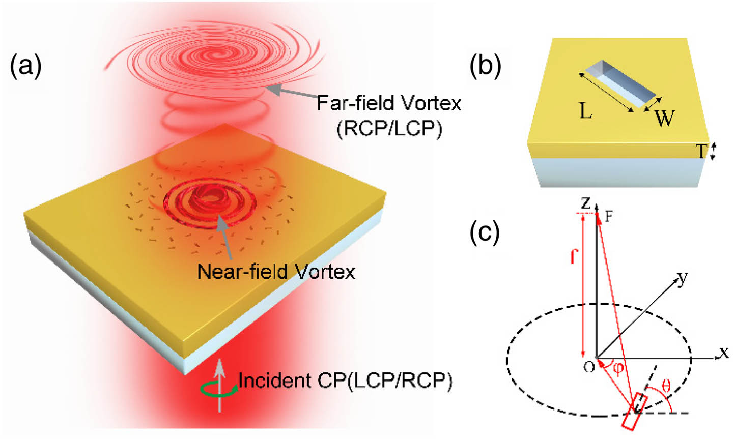
Figure 1.Bi-channel optical vortex generated in both the near and far fields. (a) Schematic of NFVG that is based on a plasmonic metasurface which consists of a nanoslit array. (b) The nanoslit on an Au film works as the building block of NFVG with width , length , and depth . The depth is also the thickness of the Au film. (c) Schematic diagram that illustrates the design principle of the bi-channel metasurface using geometric phase of the nanoslit in both the near and far fields. Under illumination of CP light with a specific spin state (LCP/RCP), the proposed metasurface can simultaneously generate focused SP vortex at the center (point ) of the metasurface and focused far-field vortex (cross-polarization, RCP/LCP) of scattered light at point with a designed focal length .
B. Simulation of a Designed NFVG
Three-dimensional finite-difference time-domain (FDTD) method simulation was used to confirm the performance of the designed NFVG in both near and far fields. Figure 2(b) shows the simulated far-field intensity distribution of the plane and the focal plane (), where a zero intensity at the center resulting from the phase singularity of the helical phase indicates the successful generation of the optical vortex. In Fig. 2(d), the four field petals of instantaneous vortex field distribution are associated with a topological charge of 2. This is consistent with Fig. 2(e), where the spatial phase distribution with two evident abrupt phase jumps from to within a azimuthal range further confirms that the generated far-field optical vortex has an integer topological charge of 2. Similarly, in Fig. 2(c), the zero intensity at the center of the metasurface indicates the generation of the SP vortex. The instantaneous intensity distribution with six field petals shown in Fig. 2(f) indicates the topological charge of the SP vortex is 3, which agrees with the three evident abrupt phase jumps of phase distribution around the center point as shown in Fig. 2(g).
C. Experimental Results
As shown in Fig. 3(a), the designed NFVG was fabricated in a 120 nm thick Au film using focused ion beam (FIB) milling. The initial Au film was deposited on a glass substrate with electron-beam vapor deposition technology. All the parameters, including the size of the nanoslit and , of the metasurface, are chosen to be the same as the FDTD simulations of Fig. 2. To experimentally demonstrate the ability of generating vortices in both the near and far fields simultaneously by this single metasurface, the near- and far-field optical measurements were implemented (see Appendix B for more details). As for the near-field characterization, SNOM was used to measure the propagation behavior of SPPs on the designed metasurface. Figure 3(d) shows the measured near-field distribution of SPPs when the metasurface is illuminated with an LCP incident beam of 671 nm, where the dark intensity spot at the center provides a direct evidence that an SP vortex (i.e., the near-field vortex) is successfully generated. Because the size of the primary ring of the SP vortex is a function of the vortex topological charge, that is, the size of the primary ring increases with topological charge, it is a practical method to judge the topological charge by comparing the primary ring size of the measured results with simulations, which has been proved as a practical method by previous studies [31,32]. To indicate that the topological charge of the generated SP vortex is consistent with the design, in Fig. 3(e), the intensity profiles of the experimental result along the and directions [corresponding to the blue and green dashed lines in Fig. 3(d), respectively] and the FDTD simulation result are plotted together and compared. The sizes of the primary ring for the experimental results are 0.956 and 0.929 μm in the and directions, respectively, which are close to the simulation result 0.880 μm. This further confirms that the near-field vortex carries a topological charge of 3 as designed. The minor size deviation of the measured result from the simulation could come from the experimental tolerance in the sample fabrication and measurements.

Figure 2.NFVG design and the simulation results. (a) The nanoslit array of a designed NFVG that can generate SP vortex and far-field vortex with topological charge of and under illumination of LCP light at 671 nm, respectively. The inner radius and outer radius are set to be 3.5 and 9 μm, and the distance between two adjacent nanoslits is . (b) Simulated optical far-field intensity of cross-polarized light (i.e., RCP light) at the plane. The inset shows the intensity distribution at the focal plane (). (c) Simulated intensity distribution of SPPs in the near field on the surface of Au film. Simulated results of (d) instantaneous vortex field distribution and (e) spatial phase profile at in the far field, respectively. Simulated results of (f) instantaneous intensity distribution and (g) spatial phase profile for SPPs in the near field, respectively.
Figure 3(b) shows the far-field intensity distribution at the plane and the focal plane (shown by the white dashed line in the plane) which was measured by a home-made far-field optical microscope. Similar to the near-field experimental result, the far-field distribution shows a dark spot at the center, which agrees well with the simulation results, and the measured focal length is consistent with the designed value . To further verify the far field is vortex, we measured the x-component intensity at [Fig. 2(c)], which shows a pair of spirals. The spirals result from the interference of LCP and RCP components in the scattered field. Because the NFVG is designed for LCP incidence, according to the Pancharatnam–Berry phase principle, the RCP component formed the focused vortex but the LCP component is unchanged. To observe obvious interference effect, the x-component intensity needs to be measured at a proper defocused plane (), where the intensity of the vortex field decreases to the level matched with the LCP light [35,36]. As shown in Fig. 2(c), the spirals indicate a helical phase distribution of the far-field optical vortex and demonstrate the vortex with a topological charge of 2 as anticipated. The excellent agreement between the experimental measurements and simulation results confirms that the proposed metasurface performs well for generating vortices in the near and far fields.
Because the proposed method is unlimited for the topological charges of near- and far-field vortices in Eqs. (1) and (2), it is quite flexible for arbitrary configuration of near- and far-field vortex generation for the CP incident light with specific spin state ( or , i.e., RCP or LCP light). To demonstrate the flexibility for different configurations of topological charges, another two samples with , (Sample A) and , (Sample B) were designed and fabricated. Other parameters of these two metasurfaces, including the geometric size of the nanoslit, , , and the far-field focal length , are the same as the former one shown in Fig. 3 (labeled as Sample C).
Figures 4(a1), 4(a3), and 4(a4) show the experimentally measured intensity distribution of both the near and far fields for Sample A, and the results of the other two samples are shown in corresponding figures in B and C. It can be observed that the focused vortex is successfully generated at the expected position in both the near and far fields for each sample and the primary ring size of the vortex increases with the rise of topological charge. In Figs. 4(a2), 4(b2), and 4(c2), the -component intensity profiles give a clear demonstration of topological charges of 3, 2, and 2 for the far-field optical vortex of Samples A, B, and C. For the near field, by comparing the size of the primary ring of the SP vortex in Figs. 4(a4), 4(b4), and 4(c4) with the simulation results (see Fig. 8 in Appendix C), the topological charges of the SP vortex generated by Samples A, B, and C are 2, 2, and 3 as designed, which coincides with the simulated instantaneous distribution of SPPs as shown in Figs. 4(a5), 4(b5), and 4(c5) (see Figs. 6 and 7 in Appendix C). Moreover, although this NFVG is proposed to generate vortices in near- and far-field channels, it can also be configured to a bi-channel metalens that can focus light in both the near and far fields when the topological charges and are set to 0 (see Appendix D), which further indicates the flexibility and versatility of this method for various applications. It is worth noting that the topological charges are not limited for our proposed NFVG, and simulations of more topological charge configurations are presented in Fig. 10 in Appendix E.
Figure 3.Experimental results of optical performances for the NFVG in the near and far fields with LCP incidence. (a) Scanning electron microscopy (SEM) images of the fabricated NFVG sample. The magnified SEM image shows the appearance of a single nanoslit. The scale bar is 5 μm. (b) Experimentally measured far-field intensity of cross-polarized light (RCP light) at the plane. The inset shows the intensity distribution at the focal plane () marked with a white dashed line in profile. (c) Measured x-component of transmitted light at . (d) SNOM measured optical near-field intensity distribution. Inset shows the zoom-in image of SPPs distribution at the center of the metasurface. (e) Comparison of the intensity profiles between measurement and simulation. The black dashed line corresponds to the simulation result. The blue and green solid lines show the field intensity along the blue and green dashed lines (i.e., and directions) in the SNOM result (d), respectively.
Figure 4.Flexibility of the proposed NFVG for different topological charge configurations. Results of the sample designed for near- and far-field topological charges of (a) , (Sample A), (b) , (Sample B), and (c) , (Sample C). Experimentally measured optical far-field intensity distributions on the transmission side of the metasurface for (a1), (b1), (c1) focal plane (); (a3), (b3), (c3) cross-sectional planes; and (a2), (b2), (c2) -component at . The left of (a3)–(c3) shows the SEM images of these three samples. (a4), (b4), (c4) SNOM measured optical near-field intensity distributions for Samples A, B, and C. (a5), (b5), (c5) Simulated instantaneous intensity distributions of SPPs in the near field for Samples A, B, and C. For all simulations and experimental measurements in (a)–(c), the incident beam is LCP light of 671 nm, and the results in (a1)–(c1) and (a3)–(c3) have filtered out the component of initial polarization to measure the cross-polarized light.
Figure 5.Schematic of the experimental setup for far-field measurement. The incident CP light is generated by a polarizer and a QWP. With an actuator, the far-field intensity distribution at different distances can be collected by the CMOS camera. In this work, the incidence is LCP light, and the cross-polarized light (RCP) is measured in the far field.
Figure 6.SEM images and far-field simulated results of Samples A and B. SEM images of fabricated (a) Sample A and (b) Sample B with FIB milling process. (c)–(h) Simulated far-field intensity distribution of RCP at the plane and corresponding intensity and phase distribution at the plane () for Sample A [(c), (e), and (f)] and Sample B [(d), (g), and (h)].
Figure 7.Simulated near-field results of Samples A and B. Simulated near-field intensity distributions of (a), (b) Sample A and (d), (e) Sample B. The simulated phase distribution of near-field SPPs of (c) Sample A and (f) Sample B. The similarity of the near-field intensity and phase distribution of these two samples confirmed the generating of near-field vortex with the same topological charge of as designed.
Figure 8.Comparison of experimental results and simulations. (a) The intensity profile of experimental results (along the white dashed line in the inset) and simulations (along the direction of intensity distribution shown in Fig. 7) of Sample A (, ). (b) The intensity profile of experimental results (along the white dashed line in the inset) and simulations of Sample B (, ). Blue dashed lines represent simulated results and the orange ones represent experimentally measured results. The measured profiles are 0.596 μm (Sample A) and 0.656 μm (Sample B), and are close to the simulation results 0.640 μm, which confirms that the generated near-field vortex has a topological charge of 2 as designed.
3. CONCLUSION
In summary, we proposed and experimentally demonstrated an integrated bi-channel vortex generator of near- and far-field vortices within a single metasurface. With the designed circular polarization incidence, the NFVG can generate vortices with specific topological charges for both near-field SPPs and far-field scattered light simultaneously. Moreover, as the topological charges of near- and far-field vortices are independent in this strategy, arbitrary configuration of OAM topological charges can be integrated into this device, which makes it quite extensible for future photonic applications. Due to the simplicity and flexibility of this design, our work provides a great potential for the application of OAM light in future high-density and multifunctional integrated optical devices. For example, it can be used in layered metadevices in which the far-field vortex can couple to another metasurface layer for other functions. Another possible application is to manipulate particles or cells at the chip surface (near field) and a distance from the surface (far field) simultaneously, which may be of value in future biotechnology.
APPENDIX A: SAMPLE FABRICATION
To fabricate the designed metasurface, a standard electron beam evaporating and an FIB milling processes were used. First, the 120?nm thick Au film was deposited onto a glass substrate with a layer of 5?nm Ti used as adhesion layers at the glass–Au interface. Then nanoslit patterns of three designed NFVGs with topological charges , (2, 2), and (2, 3) were fabricated on the Au film by using FIB milling. The scanning electron microscopy image of the fabricated NFVG with topological charges (3, 2) is shown in Fig.?3(a), and the other two are provided in Figs.?6(a) and 6(b) in Appendix?C.
APPENDIX B: EXPERIMENTAL MEASUREMENTS
A commercial SNOM (Nanonics, Multiview 2000) and a home-made microscope were used for near-field and far-field measurements, respectively. For both two field measurements, the initial incident laser beam at 671?nm was converted into LCP light by a cascaded polarizer and quarter-wave plate before illuminating onto the metasurface. For the near-field measurement, SPPs were measured by an SNOM probe which can collect SPP signals and couple them into propagating modes in the optical fiber. For the far field, the sample was mounted on a stage with an actuator, which is used to accurately control the movement of the sample along the optical axis ( axis). The transmitted light through metasurface was collected with an objective () and then passed through a cascaded quarter-wave plate and polarizer to filter out the LCP component. Subsequently, the filtered transmitted light of the cross-polarized component (i.e., the RCP light) passed through a tube lens and was imaged on a complementary metal-oxide semiconductor (CMOS) camera. To get the intensity distribution of the plane, a series of images of light intensity distribution on the plane were taken by moving the sample along the direction with a fixed step, and then the intensity at in each image was extracted to form the intensity distribution as shown in Figs.?3 and 4. A schematic of the optical setup of far-field measurement is shown in Fig.?5.
Figure 9.Simulated results of the bi-channel metalens under LCP incidence. (a) Designed patterns of the bi-channel metalens. (b) Simulated near-field intensity distribution. (c) Simulated far-field intensity distribution of RCP at the plane. (d) Simulated far-field intensity distribution at the plane [green dashed line in (c)].
Figure 10.Simulated near- and far-field distributions of NFVG with different configurations of and under LCP incidence. (a) Designed patterns with different topological charges (0 to 6) and (6 to 0). (b) Simulated intensity (upper row) and instantaneous field (lower row) distributions of near-field vortices with different topological charges. (c) Simulated intensity (upper row) and instantaneous field (lower row) distributions of far-field vortices (RCP) with different topological charges.
APPENDIX C: SIMULATION RESULTS OF SAMPLES A AND B
Figures?6 and 7 show the far-field and near-field simulations of Samples A and B, which indicate the generating of vortices in both fields. As shown in Fig.?8, the comparison of experimental results and simulations of these two samples shows that the measured profiles are 0.596?μm (Sample A) and 0.656?μm (Sample B), which are close to the simulation result (0.640?μm), and confirms that the generated near-field vortex has a topological charge of 2 as designed.
APPENDIX D: BI-CHANNEL METALENS
As a special case, when the topological charges are zero, the NFVG degrades into a bi-channel metalens, which can focus light in both the near and far fields. To simulate this case, we set and as 0, and the other parameters are the same as the designed bi-channel vortex generator in Fig.?2. As shown in Fig.?9, it is observed that this bi-channel metalens performs well in both fields.
APPENDIX E: MORE CONFIGURATIONS OF l1 AND l2
As shown in Fig.?10, more simulations are performed to demonstrate the flexibility of the proposed NFVG for different configurations of topological charges. For near-field vortices, topological charges are set as , 1, 2, 3, 4, 5, and 6. And the corresponding topological charges of far-field vortices are set as , 5, 4, 3, 2, 1, and 0. The other parameters are the same as the designed NFVG in Fig.?2. It can be observed that vortices are successfully generated in both near and far fields, and the instantaneous field distributions indicate the topological charges of generated vortices are consistent with the design.
References
[1] L. Allen, M. W. Beijersbergen, R. J. Spreeuw, J. P. Woerdman. Orbital angular momentum of light and the transformation of Laguerre-Gaussian laser modes. Phys. Rev. A, 45, 8185-8189(1992).
[2] J. Leach, M. J. Padgett, S. M. Barnett, S. Franke-Arnold, J. Courtial. Measuring the orbital angular momentum of a single photon. Phys. Rev. Lett., 88, 257901(2002).
[3] H. Huang, G. Xie, Y. Yan, N. Ahmed, Y. Ren, Y. Yue, D. Rogawski, M. J. Willner, B. I. Erkmen, K. M. Birnbaum, S. J. Dolinar, M. P. Lavery, M. J. Padgett, M. Tur, A. E. Willner. 100 Tbit/s free-space data link enabled by three-dimensional multiplexing of orbital angular momentum, polarization, and wavelength. Opt. Lett., 39, 197-200(2014).
[4] J. Wang, J. Y. Yang, I. M. Fazal, N. Ahmed, Y. Yan, H. Huang, Y. X. Ren, Y. Yue, S. Dolinar, M. Tur, A. E. Willner. Terabit free-space data transmission employing orbital angular momentum multiplexing. Nat. Photonics, 6, 488-496(2012).
[5] Y. Yan, G. Xie, M. P. Lavery, H. Huang, N. Ahmed, C. Bao, Y. Ren, Y. Cao, L. Li, Z. Zhao, A. F. Molisch, M. Tur, M. J. Padgett, A. E. Willner. High-capacity millimetre-wave communications with orbital angular momentum multiplexing. Nat. Commun., 5, 4876(2014).
[6] F. Tamburini, G. Anzolin, G. Umbriaco, A. Bianchini, C. Barbieri. Overcoming the Rayleigh criterion limit with optical vortices. Phys. Rev. Lett., 97, 163903(2006).
[7] Z. Tong, O. Korotkova. Beyond the classical Rayleigh limit with twisted light. Opt. Lett., 37, 2595-2597(2012).
[8] L. Paterson, M. P. MacDonald, J. Arlt, W. Sibbett, P. E. Bryant, K. Dholakia. Controlled rotation of optically trapped microscopic particles. Science, 292, 912-914(2001).
[9] Y. Roichman, B. Sun, Y. Roichman, J. Amato-Grill, D. G. Grier. Optical forces arising from phase gradients. Phys. Rev. Lett., 100, 013602(2008).
[10] V. Garces-Chavez, D. McGloin, M. J. Padgett, W. Dultz, H. Schmitzer, K. Dholakia. Observation of the transfer of the local angular momentum density of a multiringed light beam to an optically trapped particle. Phys. Rev. Lett., 91, 093602(2003).
[11] W. Y. Tsai, J. S. Huang, C. B. Huang. Selective trapping or rotation of isotropic dielectric microparticles by optical near field in a plasmonic Archimedes spiral. Nano Lett., 14, 547-552(2014).
[12] A. Nicolas, L. Veissier, L. Giner, E. Giacobino, D. Maxein, J. Laurat. A quantum memory for orbital angular momentum photonic qubits. Nat. Photonics, 8, 234-238(2014).
[13] M. Erhard, R. Fickler, M. Krenn, A. Zeilinger. Twisted photons: new quantum perspectives in high dimensions. Light Sci. Appl., 7, 17146(2018).
[14] N. Yu, P. Genevet, M. A. Kats, F. Aieta, J. P. Tetienne, F. Capasso, Z. Gaburro. Light propagation with phase discontinuities: generalized laws of reflection and refraction. Science, 334, 333-337(2011).
[15] J. Lin, J. P. Mueller, Q. Wang, G. Yuan, N. Antoniou, X. C. Yuan, F. Capasso. Polarization-controlled tunable directional coupling of surface plasmon polaritons. Science, 340, 331-334(2013).
[16] A. V. Kildishev, A. Boltasseva, V. M. Shalaev. Planar photonics with metasurfaces. Science, 339, 1232009(2013).
[17] N. Yu, F. Capasso. Flat optics with designer metasurfaces. Nat. Mater., 13, 139-150(2014).
[18] E. Karimi, S. A. Schulz, I. De Leon, H. Qassim, J. Upham, R. W. Boyd. Generating optical orbital angular momentum at visible wavelengths using a plasmonic metasurface. Light Sci. Appl., 3, e167(2014).
[19] F. Qin, L. Ding, L. Zhang, F. Monticone, C. C. Chum, J. Deng, S. Mei, Y. Li, J. Teng, M. Hong, S. Zhang, A. Alu, C. W. Qiu. Hybrid bilayer plasmonic metasurface efficiently manipulates visible light. Sci. Adv., 2, e1501168(2016).
[20] A. Arbabi, E. Arbabi, Y. Horie, S. M. Kamali, A. Faraon. Planar metasurface retroreflector. Nat. Photonics, 11, 415-420(2017).
[21] M. Khorasaninejad, W. T. Chen, R. C. Devlin, J. Oh, A. Y. Zhu, F. Capasso. Metalenses at visible wavelengths: diffraction-limited focusing and subwavelength resolution imaging. Science, 352, 1190-1194(2016).
[22] B. H. Chen, P. C. Wu, V. C. Su, Y. C. Lai, C. H. Chu, I. C. Lee, J. W. Chen, Y. H. Chen, Y. C. Lan, C. H. Kuan, D. P. Tsai. GaN metalens for pixel-level full-color routing at visible light. Nano Lett., 17, 6345-6352(2017).
[23] X. J. Ni, S. Ishii, A. V. Kildishev, V. M. Shalaev. Ultra-thin, planar, Babinet-inverted plasmonic metalenses. Light Sci. Appl., 2, e72(2013).
[24] Y. Bao, Q. Jiang, Y. Kang, X. Zhu, Z. Fang. Enhanced optical performance of multifocal metalens with conic shapes. Light Sci. Appl., 6, e17071(2017).
[25] S. Wang, P. C. Wu, V. C. Su, Y. C. Lai, C. Hung Chu, J. W. Chen, S. H. Lu, J. Chen, B. Xu, C. H. Kuan, T. Li, S. Zhu, D. P. Tsai. Broadband achromatic optical metasurface devices. Nat. Commun., 8, 187(2017).
[26] X. Chen, L. Huang, H. Muhlenbernd, G. Li, B. Bai, Q. Tan, G. Jin, C. W. Qiu, S. Zhang, T. Zentgraf. Dual-polarity plasmonic metalens for visible light. Nat. Commun., 3, 1198(2012).
[27] X. Li, L. Chen, Y. Li, X. Zhang, M. Pu, Z. Zhao, X. Ma, Y. Wang, M. Hong, X. Luo. Multicolor 3D meta-holography by broadband plasmonic modulation. Sci. Adv., 2, e1601102(2016).
[28] L. L. Huang, X. Z. Chen, H. Muhlenbernd, H. Zhang, S. M. Chen, B. F. Bai, Q. F. Tan, G. F. Jin, K. W. Cheah, C. W. Qiu, J. S. Li, T. Zentgraf, S. Zhang. Three-dimensional optical holography using a plasmonic metasurface. Nat. Commun., 4, 2808(2013).
[29] D. Wen, F. Yue, G. Li, G. Zheng, K. Chan, S. Chen, M. Chen, K. F. Li, P. W. Wong, K. W. Cheah, E. Y. Pun, S. Zhang, X. Chen. Helicity multiplexed broadband metasurface holograms. Nat. Commun., 6, 8241(2015).
[30] B. Desiatov, N. Mazurski, Y. Fainman, U. Levy. Polarization selective beam shaping using nanoscale dielectric metasurfaces. Opt. Express, 23, 22611-22618(2015).
[31] H. Kim, J. Park, S. W. Cho, S. Y. Lee, M. Kang, B. Lee. Synthesis and dynamic switching of surface plasmon vortices with plasmonic vortex lens. Nano Lett., 10, 529-536(2010).
[32] C. F. Chen, C. T. Ku, Y. H. Tai, P. K. Wei, H. N. Lin, C. B. Huang. Creating optical near-field orbital angular momentum in a gold metasurface. Nano Lett., 15, 2746-2750(2015).
[33] F. Yue, D. Wen, C. Zhang, B. D. Gerardot, W. Wang, S. Zhang, X. Chen. Multichannel polarization-controllable superpositions of orbital angular momentum states. Adv. Mater., 29, 1603838(2017).
[34] M. Q. Mehmood, S. Mei, S. Hussain, K. Huang, S. Y. Siew, L. Zhang, T. Zhang, X. Ling, H. Liu, J. Teng, A. Danner, S. Zhang, C. W. Qiu. Visible-frequency metasurface for structuring and spatially multiplexing optical vortices. Adv. Mater., 28, 2533-2539(2016).
[35] X. Ma, M. Pu, X. Li, C. Huang, Y. Wang, W. Pan, B. Zhao, J. Cui, C. Wang, Z. Zhao, X. Luo. A planar chiral meta-surface for optical vortex generation and focusing. Sci. Rep., 5, 10365(2015).
[36] J. Jin, J. Luo, X. Zhang, H. Gao, X. Li, M. Pu, P. Gao, Z. Zhao, X. Luo. Generation and detection of orbital angular momentum via metasurface. Sci. Rep., 6, 24286(2016).
[37] L. Marrucci, C. Manzo, D. Paparo. Optical spin-to-orbital angular momentum conversion in inhomogeneous anisotropic media. Phys. Rev. Lett., 96, 163905(2006).
[38] S. Pidishety, V. Kumar, N. K. Viswanathan. Plasmon-mediated vectorial topological dipole: formation and annihilation. Opt. Lett., 37, 4233-4235(2012).
[39] X. Cai, J. Wang, M. J. Strain, B. Johnson-Morris, J. Zhu, M. Sorel, J. L. O’Brien, M. G. Thompson, S. Yu. Integrated compact optical vortex beam emitters. Science, 338, 363-366(2012).
[40] J. Liu, S. M. Li, L. Zhu, A. D. Wang, S. Chen, C. Klitis, C. Du, Q. Mo, M. Sorel, S. Y. Yu, X. L. Cai, J. Wang. Direct fiber vector eigenmode multiplexing transmission seeded by integrated optical vortex emitters. Light Sci. Appl., 7, 17148(2018).
[41] S. Pidishety, S. Pachava, P. Gregg, S. Ramachandran, G. Brambilla, B. Srinivasan. Orbital angular momentum beam excitation using an all-fiber weakly fused mode selective coupler. Opt. Lett., 42, 4347-4350(2017).
[42] P. Vayalamkuzhi, S. Bhattacharya, U. Eigenthaler, K. Keskinbora, C. T. Samlan, M. Hirscher, J. P. Spatz, N. K. Viswanathan. Direct patterning of vortex generators on a fiber tip using a focused ion beam. Opt. Lett., 41, 2133-2136(2016).
[43] Y. J. Bao, S. Zu, W. Liu, L. Zhou, X. Zhu, Z. Y. Fang. Revealing the spin optics in conic-shaped metasurfaces. Phys. Rev. B, 95, 081406(2017).


