• Infrared and Laser Engineering
  • Vol. 51, Issue 3, 20210276 (2022)
Jun Ma
Author Affiliations
  • Beijing Institute of Space Mechanics & Electricity, Beijing 100094, China
  • show less
    DOI: 10.3788/IRLA20210276 Cite this Article
    Jun Ma. Coplanarity evaluation model of long linear LWIR detector[J]. Infrared and Laser Engineering, 2022, 51(3): 20210276 Copy Citation Text show less
    External configuration of FPA
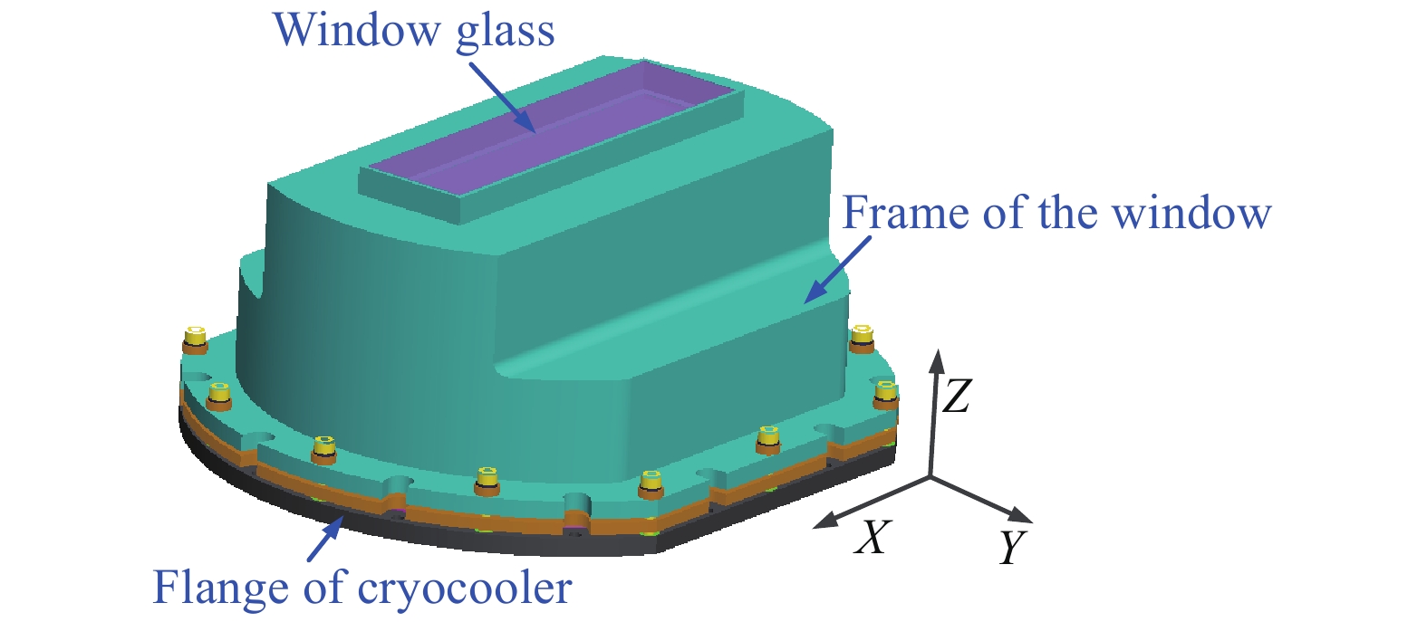
    Fig. 1. External configuration of FPA
    Section of FPA
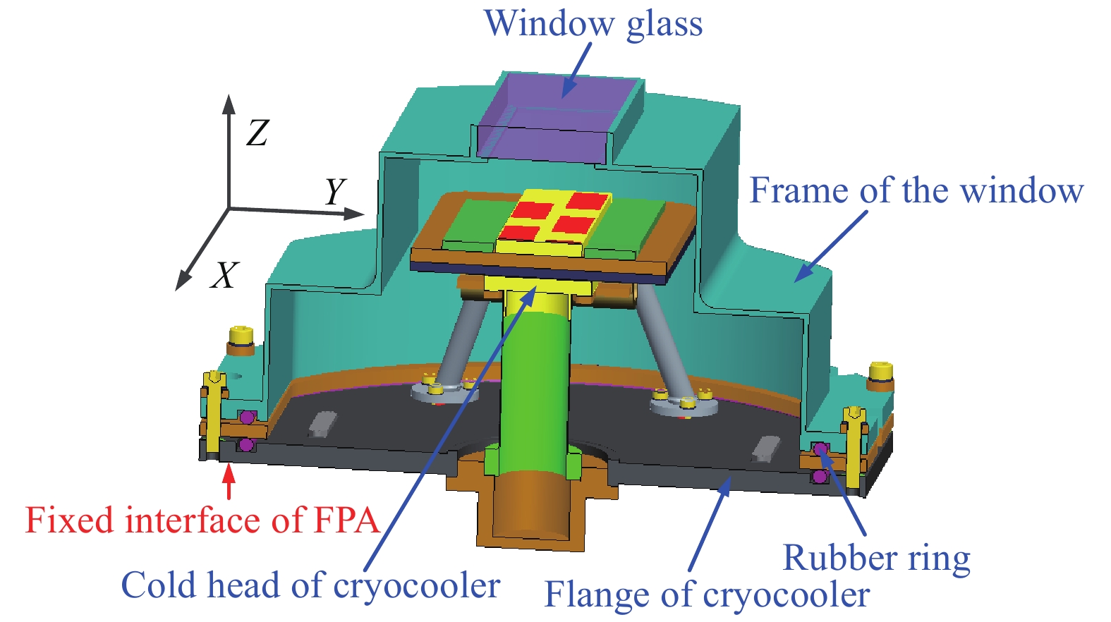
    Fig. 2. Section of FPA
    Internal configuration of FPA
    Fig. 3. Internal configuration of FPA
    FEM of FPA
    Fig. 4. FEM of FPA
    Internal force of laminates
    Fig. 5. Internal force of laminates
    Structure of isotropic laminates
    Fig. 6. Structure of isotropic laminates
    Curves of laminates flatness with the CTE of laminate 1
    Fig. 7. Curves of laminates flatness with the CTE of laminate 1
    Schematic of the division of detector area
    Fig. 8. Schematic of the division of detector area
    Curves of the flatness of butting base with the thickness of cold plate
    Fig. 9. Curves of the flatness of butting base with the thickness of cold plate
    Curves of the flatness of butting base with the CTE of cold plate
    Fig. 10. Curves of the flatness of butting base with the CTE of cold plate
    Schematic of the design improvement of laminated structure
    Fig. 11. Schematic of the design improvement of laminated structure
    Curves of the flatness of butting base with the thickness of cold plate after design improvement
    Fig. 12. Curves of the flatness of butting base with the thickness of cold plate after design improvement
    Curves of the flatness of butting base with the CTE of cold plate after design improvement
    Fig. 13. Curves of the flatness of butting base with the CTE of cold plate after design improvement
    Deformation of FPA in ground test (Unit: mm)
    Fig. 14. Deformation of FPA in ground test (Unit: mm)
    Schematic of detector flatness test
    Fig. 15. Schematic of detector flatness test
    Location of sample point in the flatness test of detector
    Fig. 16. Location of sample point in the flatness test of detector
    Case No.LoadInfluencing factor which is analyzedChanged conditions relative to basic settingsFlatness/μm
    1Packaging stressPackaging stressBasic settings−1.68
    2Packaging stress and atmospheric pressure Atmospheric pressure1 atmospheric pressure6.73
    30.5 atmospheric pressure2.53
    4Packaging stress and assembly stressFlatness of fixed interfaceForced displacement is 0.05 mm−2.47
    5Forced displacement is 0.03 mm−2.14
    6Packaging stress and temperature load Thermal stressThe temperature load is applied176.41
    7Packaging stress and temperature load Stiffness of cold chainYoung's modulus of cold chain is 14400 GPa280.44
    8Young's modulus of cold chain is 1.44 GPa154.45
    9Packaging stress and temperature load Stiffness of support poleYoung's modulus of support pole is 11000 GPa70.65
    10Young's modulus of support pole is 1.1 GPa192.61
    11Packaging stress and temperature load Coefficient of thermal expansion of cold plateCTE of cold plate is 8.0×10⁻⁶/K 349.13
    12CTE of cold plate is 1.0×10⁻⁶/K −75.85
    13Packaging stress and temperature load Thickness of cold plateThickness of cold plate is 5 mm157.93
    14Thickness of cold plate is 6.5 mm133.54
    Table 1. Flatness of butting base under different cases
    Name of monolayer Young's modulus/GPa Poisson's ratio Thickness/ mm CTE/ K−1
    Layer 11230.33.5Variable
    Layer 22020.355.80×10−6
    Layer 33350.353.26×10−6
    Table 2. Material parameters for verifying analysis
    Jun Ma. Coplanarity evaluation model of long linear LWIR detector[J]. Infrared and Laser Engineering, 2022, 51(3): 20210276
    Download Citation