
Jinlong Xiang, Yujia Zhang, Yaotian Zhao, Xuhan Guo, Yikai Su. All-optical silicon microring spiking neuron[J]. Photonics Research, 2022, 10(4): 939
- Photonics Research
- Vol. 10, Issue 4, 939 (2022)
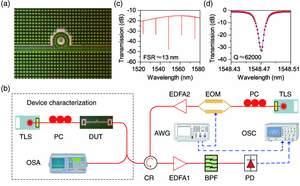
Fig. 1. (a) Microscope image of the silicon microring used in the experiment. (b) Schematic figure of the measurement setup for both characterization of the microring and investigation of its spiking dynamics. TLS, tunable laser source; PC, polarization controller; DUT, device under test; OSA, optical spectrum analyzer; CR, circulator; EDFA, erbium-doped fiber amplifier; BPF, bandpass filter; PD, photodetector; AWG, arbitrary waveform generator; OSC, oscilloscope; EOM, electro-optical modulator. (c) Non-normalized transmission of the microring. (d) Transmission of one single resonance and its Lorentz curve.
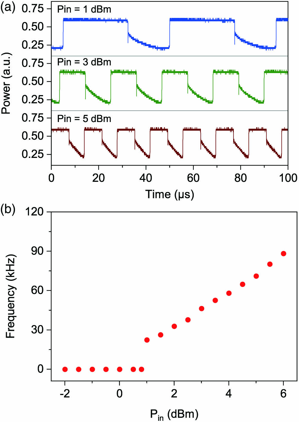
Fig. 2. (a) Measured real-time output waveform of self-pulsation for different input powers. (b) Frequency of self-pulsation in relation to pump power.
Fig. 3. (a) Measured real-time output waveform of excitability in response to perturbation pulses of increasing power. (b) Normalized strength of the “negative” spike as a function of perturbation power. The threshold area is indicated by the shaded region.
Fig. 4. (a) Simulated and (b) measured microring neuron spikes for different wavelength detuning values of the pump and perturbation light.
Fig. 5. (a) Distribution of the excitability threshold for the microring neuron over different pump powers and wavelength detuning. (b) For P in = 1 mW δ r = − 20 pm P tr = 0.6 mW P tr = 2 mW P in = 0.5 mW δ r = − 40 pm P tr = 0.5 mW P tr = 3 mW
Fig. 6. Measured real-time output waveform of refractory period with varying time intervals between two perturbation pulses. Each pulse is strong enough to excite the silicon microring neuron to emit a complete spike.
Fig. 7. Measured real-time output waveform of temporal integration with varying time intervals between two perturbation pulses. Only a subthreshold spike can be triggered by each single pulse.
Fig. 8. Measured real-time output waveform of inhibitory dynamics with varying time intervals between the excitatory and inhibitory pattens.
| ||||||||||||||||||||||||||||||||||||||||
Table 1. Summary of Major Neurocomputational Properties [4]

Set citation alerts for the article
Please enter your email address
© Copyright 2018-2021 | Chinese Laser Press. All Rights Reserved 沪ICP备15018463号-20