
Wenjie Jiang, Yongkai Yin, Junpeng Jiao, Xian Zhao, Baoqing Sun, "2,000,000 fps 2D and 3D imaging of periodic or reproducible scenes with single-pixel detectors," Photonics Res. 10, 2157 (2022)
- Photonics Research
- Vol. 10, Issue 9, 2157 (2022)
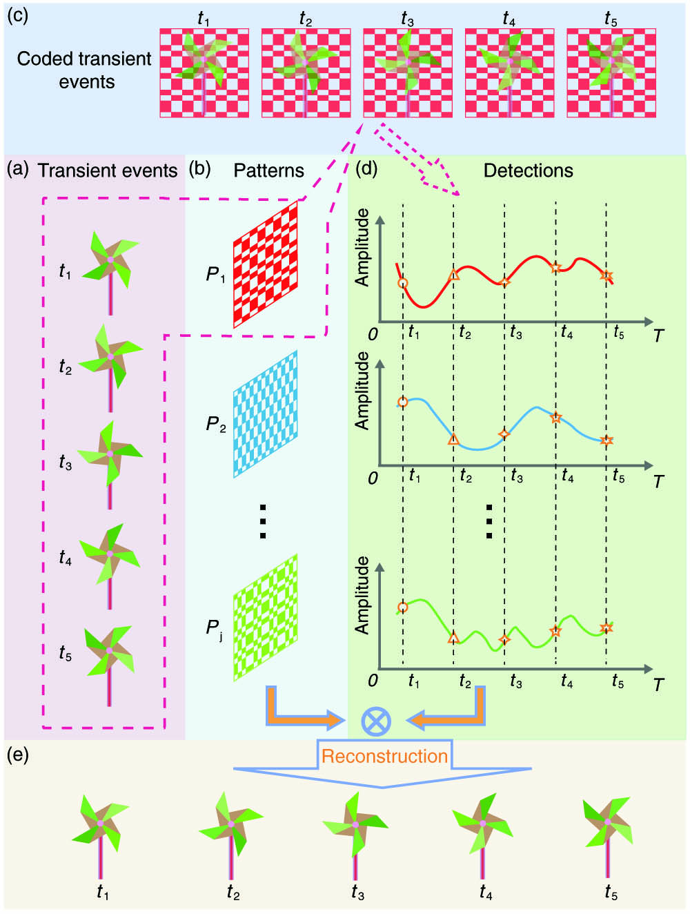
Fig. 1. Schematic diagram of TRSPI. (a) Transient events at different instants are indicated as t i P j t i
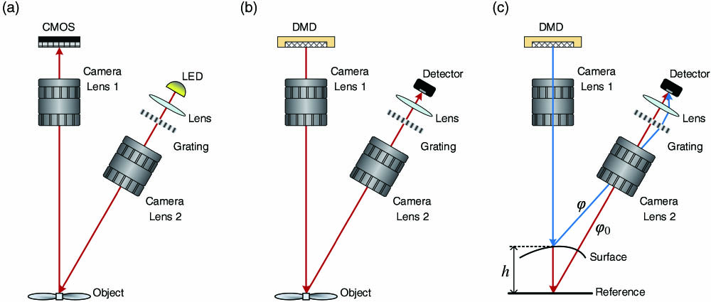
Fig. 2. Classic and reciprocal SPI configurations of FTP. (a) Classic configuration of the conventional FTP; (b) according to the Helmholtz reciprocity, a grating is added into SPI configuration for 3D imaging based on FTP theory. (c) The principle of height calculation with the phase difference between the surface of the object and the reference plane.
Fig. 3. Experimental setup of TRSPI for 2D and 3D imaging. (a) Complete TRSPI experimental configuration for 2D imaging; (b) detection module of TRSPI for 3D imaging.
Fig. 4. Measure period of a dynamic scene and digital calibration. (a) Regular checkerboard pattern loaded on the DMD when measuring the period of the dynamic scene; (b) continuous signal recorded by a single-pixel detector when the scene is illuminated by pattern (a), whose length exceeds a period of the dynamic scene. The red dashed box represents the time length of one period of the dynamic scene. (c) Digital calibration scheme when there is a slight mismatch between the period of the dynamic scene and exposure time of each illumination pattern.
Fig. 5. Selected 12 instantaneous frames from 2D TRSPI results (see Visualization 1 for more details).
Fig. 6. 3D TRSPI process based on FTP. (a) One reconstructed frame from detector 1; (b) reconstructed frame from detector 2 at the same time as in (a); (c) Fourier spectrum of (a) after background normalization; (d) positive first-order component of (c), selected with a Hann window; (e) wrapped phase obtained by inverse Fourier transform of (d); (f) reconstructed 3D shape corresponding to current frame (see Visualization 2 for more details). (g) Evaluation of the measurement uncertainty.


Set citation alerts for the article
Please enter your email address

© Copyright 2018-2021 | Chinese Laser Press. All Rights Reserved 沪ICP备15018463号-20