• Photonics Research
  • Vol. 10, Issue 2, 610 (2022)
Huabing Wu1, Xiang Xi1, Ximing Li1, Yin Poo1, Shiyang Liu2, and Rui-Xin Wu1、*
Author Affiliations
  • 1School of Electronic Science and Engineering, Nanjing University, Nanjing 200023, China
  • 2Key Laboratory of Optical Information Detecting and Display Technology, Zhejiang Normal University, Jinhua 321004, China
  • show less
    DOI: 10.1364/PRJ.437552 Cite this Article Set citation alerts
    Huabing Wu, Xiang Xi, Ximing Li, Yin Poo, Shiyang Liu, Rui-Xin Wu. Manipulating electromagnetic radiation of one-way edge states by magnetic plasmonic gradient metasurfaces[J]. Photonics Research, 2022, 10(2): 610 Copy Citation Text show less
    Electric-field patterns for a transverse magnetic (TM) Gaussian beam incident normally on the surface of a five-layer slab composed of an array of ferrite rods in (a) a square lattice and with the upmost two layers of the slab in the illuminated region replaced by a magnetic plasmonic GMS with the unit cell containing (b), (e), (f) five pairs of rod dimers. The field intensity profiles close to the interface are shown in (c), (d), (g), (h), corresponding to (a), (b), (e), (f). (i) Schematic of the unit cell, in which the structure size and the direction of the magnetic field are marked. (j) Amplified view of the near-field map of the connection area between the excitation region and propagation region of the edge modes, in which the electric-field direction of the incident wave is marked. (k)–(n) Unit cells for the corresponding slabs, among which (l)–(n) are the same. The operating frequency is 4.72 GHz, and the bias magnetic field is applied such that H0=530 Oe.
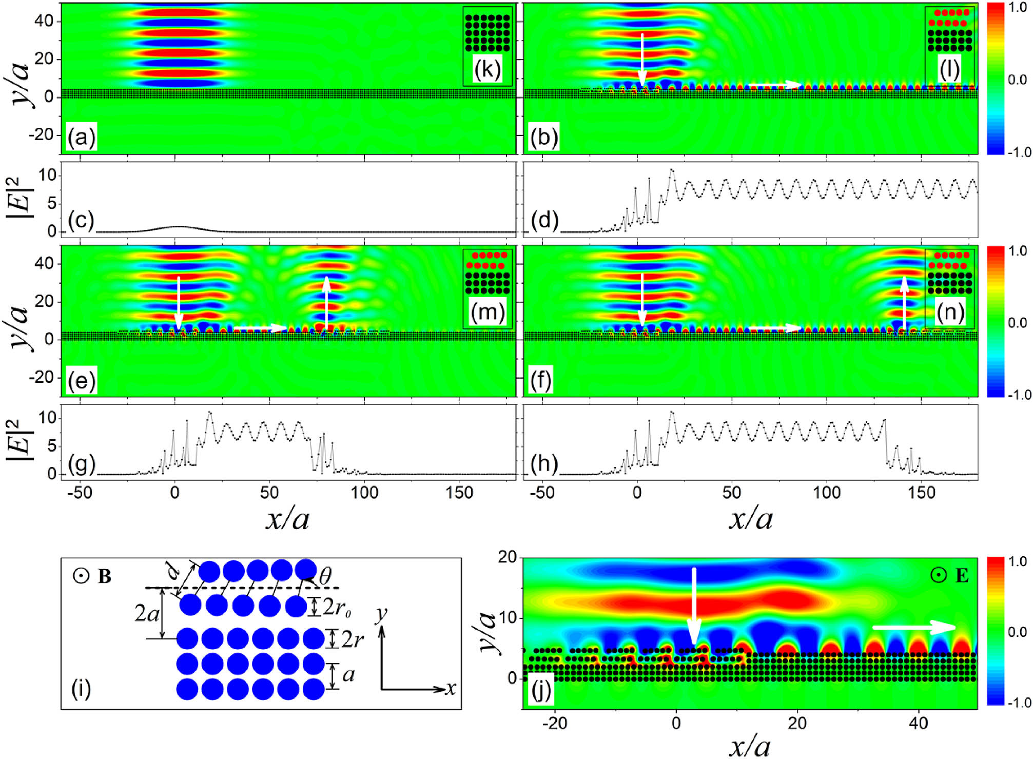
    Fig. 1. Electric-field patterns for a transverse magnetic (TM) Gaussian beam incident normally on the surface of a five-layer slab composed of an array of ferrite rods in (a) a square lattice and with the upmost two layers of the slab in the illuminated region replaced by a magnetic plasmonic GMS with the unit cell containing (b), (e), (f) five pairs of rod dimers. The field intensity profiles close to the interface are shown in (c), (d), (g), (h), corresponding to (a), (b), (e), (f). (i) Schematic of the unit cell, in which the structure size and the direction of the magnetic field are marked. (j) Amplified view of the near-field map of the connection area between the excitation region and propagation region of the edge modes, in which the electric-field direction of the incident wave is marked. (k)–(n) Unit cells for the corresponding slabs, among which (l)–(n) are the same. The operating frequency is 4.72 GHz, and the bias magnetic field is applied such that H0=530  Oe.
    Conversion efficiency is plotted as a function of incident angle θinc for the ordinary periodic surface (black diamond line) and GMSs with the rotational angle uniformly varying from 45° to 60° (red circles), 60° to 75° (blue triangles), and 75° to 90° (magenta triangles). The working frequency is 4.72 GHz, and the other parameters are the same as those in Fig. 1.
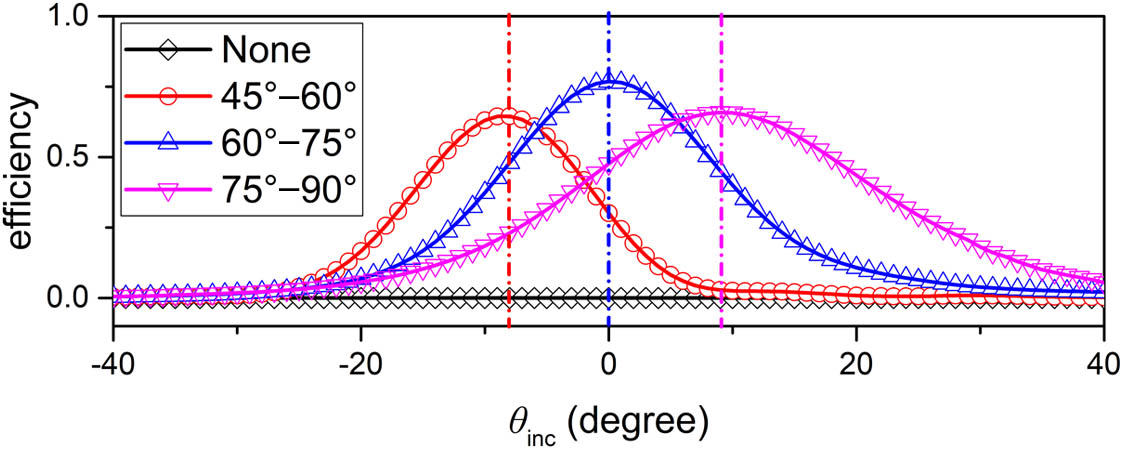
    Fig. 2. Conversion efficiency is plotted as a function of incident angle θinc for the ordinary periodic surface (black diamond line) and GMSs with the rotational angle uniformly varying from 45° to 60° (red circles), 60° to 75° (blue triangles), and 75° to 90° (magenta triangles). The working frequency is 4.72 GHz, and the other parameters are the same as those in Fig. 1.
    (a) Photonic dispersion curves for the bulk magnetic metamaterial of the square lattice, showing a photonic bandgap (PBG) on top of the flat bands. (b) Photonic dispersion curves of edge modes along the Γ−x direction for the five-layer slab cutting out from the magnetic metamaterial with the unit cell shown in Fig. 1(k) (black squares) and that with the upmost two layers replaced by the GMS, whose unit cell contains five pairs of rod dimers with the rotational angle θ uniformly varying from 45° to 60° (red circles), 60° to 75° as shown in Fig. 1(l) (blue triangles), and 75° to 90° (magenta triangles), and the bias magnetic field is applied such that H0=530 Oe. (c) Photonic dispersion curves of edge modes for a fixed magnetic GMS with the rotational angle ranging from 75° to 90°; rod dimers under three different bias magnetic fields such that H0 is equal to 530, 550, and 570 Oe, and the substrate has the same H0 equal to 530 Oe. The green dashed line marks the working frequency at 4.72 GHz in Figs. 1, 2, 4, and 5, and the solid yellow lines mark the light lines. The other parameters are the same as those in Fig. 1.
    Fig. 3. (a) Photonic dispersion curves for the bulk magnetic metamaterial of the square lattice, showing a photonic bandgap (PBG) on top of the flat bands. (b) Photonic dispersion curves of edge modes along the Γx direction for the five-layer slab cutting out from the magnetic metamaterial with the unit cell shown in Fig. 1(k) (black squares) and that with the upmost two layers replaced by the GMS, whose unit cell contains five pairs of rod dimers with the rotational angle θ uniformly varying from 45° to 60° (red circles), 60° to 75° as shown in Fig. 1(l) (blue triangles), and 75° to 90° (magenta triangles), and the bias magnetic field is applied such that H0=530  Oe. (c) Photonic dispersion curves of edge modes for a fixed magnetic GMS with the rotational angle ranging from 75° to 90°; rod dimers under three different bias magnetic fields such that H0 is equal to 530, 550, and 570 Oe, and the substrate has the same H0 equal to 530 Oe. The green dashed line marks the working frequency at 4.72 GHz in Figs. 1, 2, 4, and 5, and the solid yellow lines mark the light lines. The other parameters are the same as those in Fig. 1.
    Manipulating the radiation characteristics of the edge modes intrinsically by tuning the gradients of magnetic GMSs outside the illuminated region with rotational angles ranging from (a) 45° to 60°; (b), (f) 60° to 75°; and (e) 75° to 90°, and a fixed magnetic GMS in the region subject to illumination of the Gaussian beam with the rotational angle ranging from 60° to 75°. The radiation angles corresponding to (a), (b), (e), and (f) are −8°, 0°, 9°, and 0°, respectively. The field intensity profiles close to the interface are shown in (c), (d), (g), and (h), corresponding to (a), (b), (e), and (f), respectively. (i)–(l) Unit cells for the corresponding slabs, among which (j) and (l) are the same. (m) Amplified view of the near-field map near the defect in (f). The working frequency is 4.72 GHz, and the other parameters are the same as those in Fig. 1.
    Fig. 4. Manipulating the radiation characteristics of the edge modes intrinsically by tuning the gradients of magnetic GMSs outside the illuminated region with rotational angles ranging from (a) 45° to 60°; (b), (f) 60° to 75°; and (e) 75° to 90°, and a fixed magnetic GMS in the region subject to illumination of the Gaussian beam with the rotational angle ranging from 60° to 75°. The radiation angles corresponding to (a), (b), (e), and (f) are 8°, 0°, 9°, and 0°, respectively. The field intensity profiles close to the interface are shown in (c), (d), (g), and (h), corresponding to (a), (b), (e), and (f), respectively. (i)–(l) Unit cells for the corresponding slabs, among which (j) and (l) are the same. (m) Amplified view of the near-field map near the defect in (f). The working frequency is 4.72 GHz, and the other parameters are the same as those in Fig. 1.
    Manipulating the radiation characteristics of edge modes extrinsically by tuning the bias magnetic field of the rod dimers outside the illuminated region with (a) H0=530 Oe, (b) H0=550 Oe, and (c) H0=570 Oe, and the other ferrite rods have the same H0=530 Oe. The radiation angles are (a) 9°, (b) 0°, and (c) −8°. The magnetic GMS has a rotational angle ranging from 75° to 90°, as in Fig. 4(e), the working frequency is 4.72 GHz, and the other parameters are the same as those in Fig. 1.
    Fig. 5. Manipulating the radiation characteristics of edge modes extrinsically by tuning the bias magnetic field of the rod dimers outside the illuminated region with (a) H0=530  Oe, (b) H0=550  Oe, and (c) H0=570  Oe, and the other ferrite rods have the same H0=530  Oe. The radiation angles are (a) 9°, (b) 0°, and (c) 8°. The magnetic GMS has a rotational angle ranging from 75° to 90°, as in Fig. 4(e), the working frequency is 4.72 GHz, and the other parameters are the same as those in Fig. 1.
    (a) Electric-field pattern for a TM Gaussian beam incident normally on the ordinary periodic surface. (b) Upmost two layers of the slab in the illuminated region replaced by a magnetic plasmonic GMS. (e) Image of the experimental sample with the top plate removed. The magenta star marks the position of the line source. (f) Electric-field pattern for the conditions of the experimental setup in (e). The field intensity profiles for the theoretical results (black line) and experimental results (red line) are shown in (c) and (d), corresponding to (a) and (b), respectively. (g) Field intensity profiles for the radiation field of a one-way edge state. The working frequency is 4.72 GHz for experiments and simulations, and the bias magnetic field is applied such that H0=530 Oe. The beam-waist radius of the Gaussian beam is w0=0.5λ.
    Fig. 6. (a) Electric-field pattern for a TM Gaussian beam incident normally on the ordinary periodic surface. (b) Upmost two layers of the slab in the illuminated region replaced by a magnetic plasmonic GMS. (e) Image of the experimental sample with the top plate removed. The magenta star marks the position of the line source. (f) Electric-field pattern for the conditions of the experimental setup in (e). The field intensity profiles for the theoretical results (black line) and experimental results (red line) are shown in (c) and (d), corresponding to (a) and (b), respectively. (g) Field intensity profiles for the radiation field of a one-way edge state. The working frequency is 4.72 GHz for experiments and simulations, and the bias magnetic field is applied such that H0=530  Oe. The beam-waist radius of the Gaussian beam is w0=0.5λ.
    Huabing Wu, Xiang Xi, Ximing Li, Yin Poo, Shiyang Liu, Rui-Xin Wu. Manipulating electromagnetic radiation of one-way edge states by magnetic plasmonic gradient metasurfaces[J]. Photonics Research, 2022, 10(2): 610
    Download Citation