
Huabing Wu, Xiang Xi, Ximing Li, Yin Poo, Shiyang Liu, Rui-Xin Wu. Manipulating electromagnetic radiation of one-way edge states by magnetic plasmonic gradient metasurfaces[J]. Photonics Research, 2022, 10(2): 610
- Photonics Research
- Vol. 10, Issue 2, 610 (2022)
Abstract
1. INTRODUCTION
Over the last few decades, one-way edge states [1–24] have flourished as an exciting field and captured considerable attention in both fundamental research and applied science. The quantized Hall effect for electrons in heterostructures comes from the Hall current, which is believed to be carried by an edge state [10] with macroscopic circulation. Inspired by these fascinating discoveries in electronic systems, there has been interest in exploring this effect in photonic systems, where the electronic current is replaced by currents of electromagnetic radiation [11–16]. The one-way propagation effect has been proved theoretically and experimentally based on photonic crystals [17–19], which has opened the way for research on topological photonics. The topological edge state has set off a research boom due to its excellent topological properties, such as robustness, defect immunity, and backscattering suppression [20–24]. Also, another type of one-way edge state associated with a magnetic surface-plasmon (MSP) has been proposed [25]. Compared with the electromagnetic edge state based on analogy of the quantum Hall effect, the MSP [15,16,26–34] based edge state does not need to rely on the periodicity of photonic crystals and can work even on homogeneous bulk systems. As a result, such edge states exhibit surface-morphology-independent characteristics, adding considerable flexibility to wave manipulation. However, one-way edge states are localized modes that cannot be excited by spatial waves. This limitation causes difficulties in applications.
Metasurfaces are types of two-dimensional planar metamaterials [35,36] that enable simultaneous control over amplitude, phase, and even polarization of photons by rectifying their interactions with gradient metasurfaces (GMSs), giving rise to a variety of novel functionalities with high performance. Furthermore, GMSs exhibit superior properties, such as low cost, low loss, easy fabrication, and, most importantly, integration compatibility for photonics and electronics [35]. Quite many striking physical phenomena ranging from wavefront shaping [37,38] and anomalous reflection and refraction [39,40] to polarization conversion [41,42] and the photonic spin Hall effect [43,44] were implemented theoretically and experimentally, resulting in a great deal of promising applications from ultrathin wave plates [45,46] and metalenses [47,48] to hologram design [49,50] and dynamic color display [51,52]. In addition, GMSs can also be employed to excite and guide a surface wave and realize phase control [53,54]. Therefore, GMSs can serve to bridge spatially propagating waves and one-way edge states. However, the performance and related features have been rarely considered so far.
In this paper, we aim to design a kind of GMS with ferrite materials, termed magnetic plasmonic GMSs due to the excitation of MSP resonance [31]. Different from the conventional GMSs made of dielectric or metallic materials, magnetic plasmonic GMSs possess nonreciprocity in virtue of the time-reversal-symmetry-breaking nature of ferrite materials under a bias magnetic field, and are further enhanced by MSP resonance [15]. The spatial propagating wave coupled into and excited by the one-way edge state is observed. The coupling and excitation are shown to be tuned either intrinsically by the gradient of the GMSs or extrinsically by the bias magnetic field. As a result, GMSs can serve as high-efficiency transformers of spatial propagating waves and one-way edge states, and the transformation can be controlled. The physical mechanism and nonreciprocal behavior can be clearly identified by examining the photonic dispersion curves. The experimental results are in good agreement with the numerical results. The results can be further extended to design nonreciprocal metasurfaces with more exquisite configurations so that novel physics and potential applications can be expected.
Sign up for Photonics Research TOC. Get the latest issue of Photonics Research delivered right to you!Sign up now
2. EXCITATION AND RADIATION OF ONE-WAY EDGE STATE
To be specific, the magnetic plasmonic GMS is composed of an array of ferrite rod dimers with a rotational gradient introduced in the unit cell as illustrated in the insets of Fig. 1. The single-crystal yttrium iron garnet is used for ferrite rods due to the extremely low loss. The electric permittivity of the ferrite rods is , and the magnetic permeability of the fully magnetized ferrite rods along rod axes, namely, the direction, is given by [55]
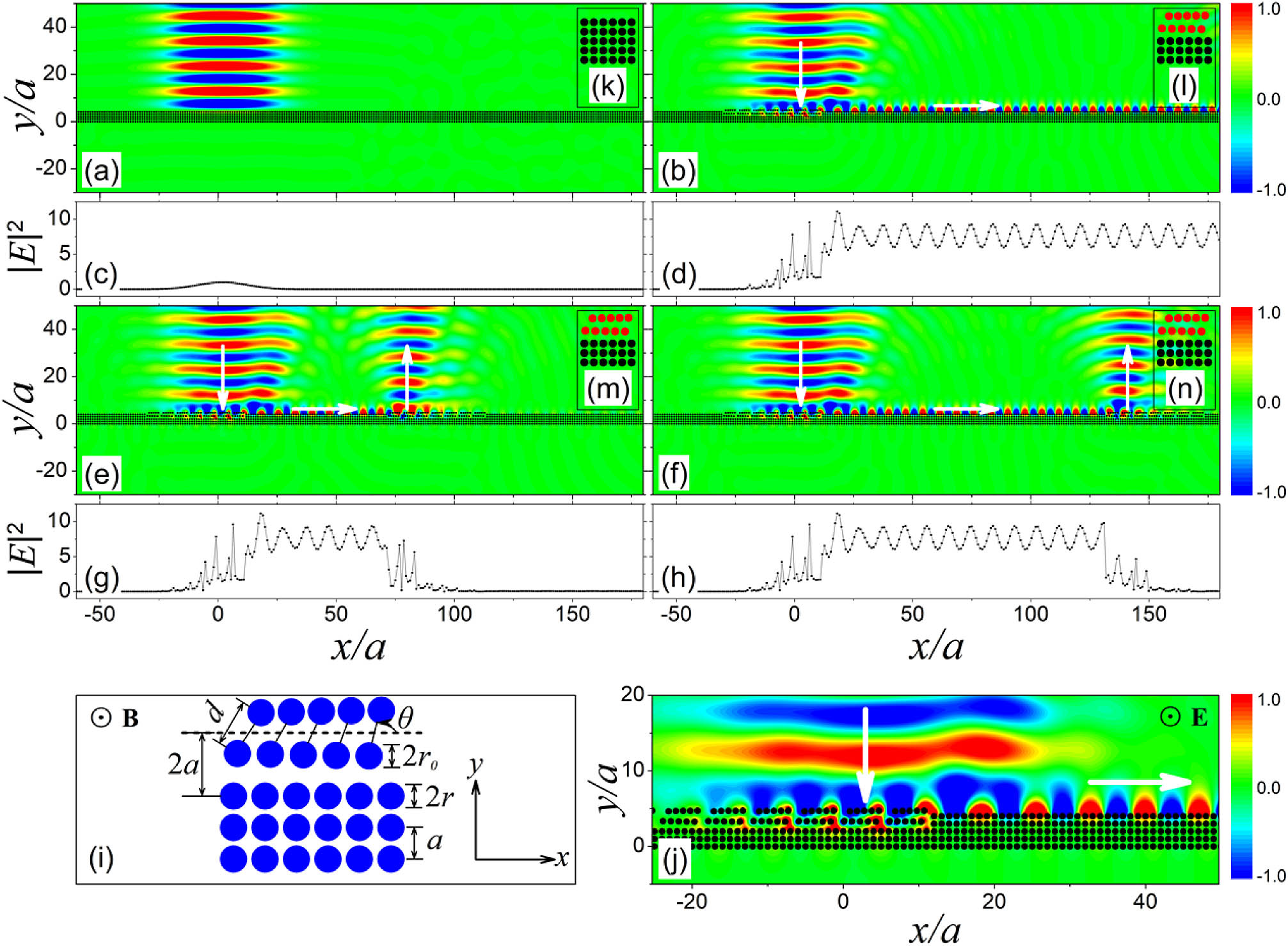
Figure 1.Electric-field patterns for a transverse magnetic (TM) Gaussian beam incident normally on the surface of a five-layer slab composed of an array of ferrite rods in (a) a square lattice and with the upmost two layers of the slab in the illuminated region replaced by a magnetic plasmonic GMS with the unit cell containing (b), (e), (f) five pairs of rod dimers. The field intensity profiles close to the interface are shown in (c), (d), (g), (h), corresponding to (a), (b), (e), (f). (i) Schematic of the unit cell, in which the structure size and the direction of the magnetic field are marked. (j) Amplified view of the near-field map of the connection area between the excitation region and propagation region of the edge modes, in which the electric-field direction of the incident wave is marked. (k)–(n) Unit cells for the corresponding slabs, among which (l)–(n) are the same. The operating frequency is 4.72 GHz, and the bias magnetic field is applied such that
As a paradigm, we first consider an ordinary periodic surface of a five-layer slab consisting of an array of ferrite rods arranged as a square lattice in air. The lattice separation is , the rod radius is , and the bias magnetic field is applied such that . The total reflection of a normally incident Gaussian beam is observed as shown in Fig. 1(a), and there appears no one-way edge state along the surface from the field intensity profile close to the interface in Fig. 1(c). The scenario is similar to the case of a dielectric or metallic surface for a normally incident Gaussian beam. Then, we examine the performance for the upmost two layers replaced by the GMSs with the unit cell consisting of an array of rod dimers. The schematic of the structure is shown in Fig. 1(i). The size of the unit cell is , the interparticle separation of the rod dimer is with a rod radius of , and an appropriate rotational gradient is introduced into the unit cell. In this case, the rest of the three-layer slab beneath serves as the substrate. GMSs are introduced into the region subject to illumination of the Gaussian beam. Outside the illuminated region, the surface layer has the same period as the substrate. For the unit cell containing five pairs of equally separated rod dimers with the rotational angle uniformly varying from 60° to 75°, the configuration is shown in the inset Fig. 1(l). Differently, the results are shown in Figs. 1(b) and 1(d), where we can find explicitly the excitation of the one-way edge state, coincident with the mechanism in other systems [53]. To more clearly observe the excitation of the one-way edge state on the magnetic plasmonic GMSs, we simulated the electric-field patterns of the connection area between the excitation region and the propagation region, as shown in Fig. 1(j). It should be pointed out that there exists offset between the centers of the incident Gaussian beam and the boundary of the excitation region, which can realize a higher conversion efficiency. To quantitatively characterize the conversion efficiency, we defined a rightward transmitted power ratio as follows:
![]()
Figure 2.Conversion efficiency is plotted as a function of incident angle
In addition to the excitation of one-way edge states, magnetic GMSs can also control and radiate electromagnetic waves. For convenience, we consider only the case of a Gaussian beam incident normally on the surface. As shown in Figs. 1(e) and 1(g), GMSs are reintroduced into the region at a distance of away from the illumination of the Gaussian beam, and evident radiation of a one-way edge state can be observed. The unit cell containing five pairs of rod dimers with the same range of rotational angles is shown in the inset Fig. 1(m), and the other parameters are the same as those in Fig. 1(b). It is remarkable that the region of the radiation of electromagnetic waves depends only on the position of the reintroduced GMSs. To verify this phenomenon, we introduced GMSs at a distance of from the illumination of the Gaussian beam as demonstrated in Figs. 1(f) and 1(h), and evident radiation of a one-way edge state can also be observed. With the extremely low loss of ferrite rods, the one-way edge state can be transmitted and radiated almost lossless on GMSs, which can be seen from the field intensity profile shown in Figs. 1(d), 1(g), and 1(h). Therefore, such a system is the desired bridge between spatially propagating waves and one-way edge states. Our findings may pave the way for many applications, including surface plasmon couplers, microwave radiation antennas, light absorbers, and so on.
3. PHOTONIC DISPERSION CURVES OF ONE-WAY EDGE STATE
To gain a deeper understanding of the phenomenon, we calculate the photonic dispersion curves as shown in Fig. 3 where a photonic bandgap (PBG) can be observed for the magnetic metamaterials due to MSP resonance [31], indicated by a dense set of flat bands, so that the Gaussian beam can be totally reflected as shown in Fig. 1(a). Then, we also calculate the dispersion curves of edge modes for different interfaces as plotted in Fig. 3(b) to illustrate the excitation of the one-way edge state shown in Fig. 1. For the five-layer slab considered in Fig. 1(a), the dispersion curves are two symmetric branches inside the PBG as marked by the black squares in Fig. 3(b). The branches on the left half (right half) correspond to the edge states confined on the upper (lower) surface. But they actually lie outside the light cone since the periodicity along the direction is , not , resulting in the band folding. The usage of the unit cell in Fig. 1(k) is just for the convenience of comparison. As a result, the incident Gaussian beam cannot be coupled to the edge mode so that no one-way edge state can be excited, explaining the total reflection of the Gaussian beam in Fig. 1(a). Differently, for the four-layer slab in Figs. 1(b), 1(e), and 1(f) with the unit cell containing five pairs of rod dimers in Figs. 1(l), 1(m), and 1(n), the dispersion curves lie inside the light cone as shown in Fig. 3(b), denoted by blue triangles, where the high density of states and a match of the parallel component of the wave vector at a working frequency of 4.72 GHz for normal incidence ensure strong coupling of the incident Gaussian beam with the edge modes as shown in Figs. 1(b), 1(e), and 1(f), resulting in excitation of the one-way edge state. It is worthwhile to point out that the one-way edge state on the ordinary periodic surface cannot decouple back into a spatially propagating wave due to the dispersion curves lying outside the light cone. However, for the edge modes of GMSs, the dispersion curves lie inside the light cone. Therefore, the one-way edge state can decouple back into a spatially propagating wave, and the GMSs can serve to manipulate the radiation of one-way edge states. By tuning the range of rotational angles in the unit cells, the dispersion curves can be flexibly controlled, adding additional degrees of freedom in manipulating the radiation of electromagnetic waves.
![]()
Figure 3.(a) Photonic dispersion curves for the bulk magnetic metamaterial of the square lattice, showing a photonic bandgap (PBG) on top of the flat bands. (b) Photonic dispersion curves of edge modes along the
From the photonic dispersion curves in Fig. 3(b), it can be found that the magnetic GMS with different rotational gradients radiated the edge modes to different directions, and the radiation angle can be calculated analytically as follows:
4. TUNABILITY BY THE ROTATIONAL GRADIENT AND BIAS MAGNETIC FIELD
From the aforementioned analysis, it can be found that the radiation characteristics of edge modes depend on the rotational gradient of magnetic GMS as illustrated from both the photonic dispersion curves and electric-field patterns. To present an even clearer picture, we simulated the field patterns for magnetic GMSs with different rotational gradients. When the rotational angle in the unit cell is decreased to a smaller range from 45° to 60°, the photonic dispersion curves of the edge mode are shown in Fig. 3(b), denoted by the red circles, where the parallel wave vector at the working frequency of 4.72 GHz. Based on Eq. (4), we can calculate the radiation angle , and the associated field pattern is shown in Fig. 4(a). On the contrary, for the magnetic GMS with a rotational angle in the unit cell increased to the range from 75° to 90°, the photonic dispersion curves of the edge mode are shown in Fig. 3(b), denoted by the magenta triangles, where the parallel wave vector at the working frequency of 4.72 GHz. Based on Eq. (4), we can also calculate the radiation angle , and the associated field pattern is shown in Fig. 4(e). Figures 4(b) and 4(d) are the same as Figs. 1(f) and 1(h), given here just for the convenience of comparison. To verify the defect immunity of wave propagation on the edge of the magnetic GMS, we removed one ferrite rod from the ordinary periodic surface, and the associated field pattern is shown in Fig. 4(f). From the inset of Fig. 4(f), we see that the electromagnetic wave automatically circumvents the defect and keeps propagating instead of being backscattered, illustrating the robust feature of the wave propagation.
![]()
Figure 4.Manipulating the radiation characteristics of the edge modes intrinsically by tuning the gradients of magnetic GMSs outside the illuminated region with rotational angles ranging from (a) 45° to 60°; (b), (f) 60° to 75°; and (e) 75° to 90°, and a fixed magnetic GMS in the region subject to illumination of the Gaussian beam with the rotational angle ranging from 60° to 75°. The radiation angles corresponding to (a), (b), (e), and (f) are
By tuning the configuration of the magnetic GMS, we intrinsically change the morphology of GMSs. It can be used to control the electromagnetic properties of the magnetic GMS, offering tunability on the radiation characteristics of edge modes. However, it is not convenient in experiment or in exploring possible applications. To implement the controllability with more degrees of freedom, extrinsic manipulation is preferred. Concretely, for a specific magnetic GMS with a rotational angle ranging from 75° to 90°, we can tune the bias magnetic field so that the electromagnetic properties can be freely adjusted. As typical examples, the photonic dispersion curves of edge modes for rod dimers under three different bias magnetic fields are shown in Fig. 3(c) where the parallel component of the wave vector is altered from to at the operating frequency, similar to the intrinsic control in Fig. 3(b). For both intrinsic and extrinsic cases, we note that the radiation angle is changed from negative to positive. To be specific, in Fig. 3(c), by tuning from 530 to 570 Oe, the radiation angle is altered from 9° to . However, we should point out that for the magnetic GMS considered here, the controllable range of the radiation angle is still not large enough. Fortunately, the one-way edge state can be switched to the opposite direction by reversing the magnetization, which cannot be observed in a nonmagnetic system, offering an additional degree of freedom in manipulating electromagnetic waves.
To present an even clearer illustration of how the radiation characteristics of edge modes are controlled by the bias magnetic field, we simulated electric-field patterns under three different bias magnetic fields. The results are shown in Fig. 5 where we can find that the radiation angles of the edge modes are 9°, 0°, and under , 550, and 570 Oe, respectively, as shown in Figs. 5(a)–5(c). This variation indicates that the edge mode can be modulated by the bias magnetic field so that the radiation angle is changed, in agreement with the above analysis. The field pattern in Fig. 5(a) is actually the same as in Fig. 4(e), given here just for the convenience of comparison. Following this concept, we can expect even more nonreciprocal functionalities implemented by magnetic GMSs.
![]()
Figure 5.Manipulating the radiation characteristics of edge modes extrinsically by tuning the bias magnetic field of the rod dimers outside the illuminated region with (a)
5. EXPERIMENTAL RESULTS AND DISCUSSION
We conducted microwave experiments to demonstrate the coupling and radiation of electromagnetic waves based on MSP. It should be noted that in our previous work [34], the rod radii of the substrate and rod dimers are different, which will not cause any problems in the simulation, because we assume that all the ferrite rods have the same magnetization. However, in the experiment, the demagnetization factors of ferrite rods with different radii are different, so the magnetization of the rods is also different under the same magnetic field. In this work, we redesigned the geometrical parameters of the GMS; all ferrite rods have the same radius. The magnetic GMS samples were fabricated with commercial single-crystal yttrium iron garnet ferrite rods, whose material parameters were the same as those used in the dispersion curve calculations, except that the rods had finite height .
The experimental setup for the radiation of a one-way edge state is shown in Fig. 6(e). The sample is surrounded by absorbers with only one edge exposed to air. The sample was sandwiched between two parallel metallic plates with a gap of 10 mm, which supports TEM mode waves of up to 15 GHz. The incident wave beam was formed in the waveguide, which was excited by a line source. In the waveguide, the field was polarized perpendicularly to the metallic plates. The wave beam was perpendicularly projected on the sample away from the waveguide port about . A probe was used to measure the field intensity profiles close to the interface. The measurements were made with the Agilent PNA-X N5247A vector network analyzer. A uniform bias magnetic field along the axis was provided by a big Helmholtz coil with an inner diameter of 260 mm, which was large enough to guarantee a spatial uniform bias magnetic field.
![]()
Figure 6.(a) Electric-field pattern for a TM Gaussian beam incident normally on the ordinary periodic surface. (b) Upmost two layers of the slab in the illuminated region replaced by a magnetic plasmonic GMS. (e) Image of the experimental sample with the top plate removed. The magenta star marks the position of the line source. (f) Electric-field pattern for the conditions of the experimental setup in (e). The field intensity profiles for the theoretical results (black line) and experimental results (red line) are shown in (c) and (d), corresponding to (a) and (b), respectively. (g) Field intensity profiles for the radiation field of a one-way edge state. The working frequency is 4.72 GHz for experiments and simulations, and the bias magnetic field is applied such that
For an ordinary periodic surface of a five-layer slab, theoretically, the total reflection to the normally incident Gaussian beam is observed, as shown in Fig. 6(a). The surface field intensity profile shows the field is localized in the region where the incident beam width is covered. Out of the region, the field tends to zero, indicating no one-way edge state is excited. The experimental results (red line) are in good agreement with the numerical results (black line), as shown in Fig. 6(c). Then, we examine the performance of magnetic GMSs; the simulation result is shown in Fig. 6(b), and the measured field intensity profiles along the surface are shown in Fig. 6(d), where we can find that the field is not only localized near the incident wave beam center but also present at a surface away from the center, which shows explicitly the excitation of the one-way edge state. The measured results (red line) well fit the numerical simulation (black line). However, it should be pointed out that the field intensity in Fig. 6(d) is much weaker than in Fig. 1(d) due to the relatively smaller amount of incident energy illuminating the sample.
Under the conditions of the experimental setup in Fig. 6(e), we simulated the field pattern of the real experimental setup by COMSOL Multiphysics, as shown in Fig. 6(f). The measured results (red line) are in good agreement with the numerical results (black line) shown in Fig. 6(g). The experiments demonstrate that magnetic GMSs can convert a spatially propagating wave to a one-way edge state, and the excited one-way edge state can also be radiated to free space.
6. CONCLUSION
In conclusion, we have designed a kind of magnetic plasmonic GMS to bridge spatial propagating waves and one-way edge states. The one-way edge state can be radiated to or excited from different angles by either intrinsically tuning the gradient of the GMSs or extrinsically tuning the bias magnetic field for a specified magnetic GMS. The physical mechanism can be discovered by examining the dispersion curve of the edge mode where a single branch of the dispersion curve signifies the nonreciprocal characteristic of magnetic GMSs, and the variation of dispersion curves with respect to the rotational gradient and the bias magnetic field explains the controllability of the radiation angle. In particular, the extrinsic manipulation with a bias magnetic field can flexibly control the radiation angle, operating frequency, and direction of the one-way edge state. Our findings provide an efficient way to couple and radiate electromagnetic waves based on GMSs. It is anticipated that our results on magnetic GMSs can also be generalized to topological physics.
Acknowledgment
Acknowledgment. The authors acknowledge assistance from the project funded by Priority Academic Program Development of Jiangsu Higher Education Institutions and Jiangsu Provincial Key Laboratory of Advanced Manipulating Technique of Electromagnetic Wave.
References
[1] M. Rechtsman, J. Zeuner, Y. Plotnik, Y. Lumer, D. Podolsky, F. Dreisow, S. Nolte, M. Segev, A. Szameit. Photonic Floquet topological insulators. Nature, 496, 196-200(2013).
[2] R. Süsstrunk, S. Huber. Observation of phononic helical edge states in a mechanical topological insulator. Science, 349, 47-50(2015).
[3] P. H. Zhou, G. G. Liu, Y. H. Yang, Y. H. Hu, S. L. Ma, H. R. Xue, Q. Wang, L. J. Deng, B. L. Zhang. Observation of photonic antichiral edge states. Phys. Rev. Lett., 125, 263603(2020).
[4] G. Harari, M. A. Bandres, Y. Lumer, M. C. Rechtsman, Y. D. Chong, M. Khajavikhan, D. N. Christodoulides, M. Segev. Topological insulator laser: theory. Science, 359, eaar4003(2018).
[5] M. A. Bandres, S. Wittek, G. Harari, M. Parto, J. Ren, M. Segev, D. N. Christodoulides, M. Khajavikhan. Topological insulator laser: experiments. Science, 359, eaar4005(2018).
[6] M. Parto, S. Wittek, H. Hodaei, G. Harari, M. A. Bandres, J. Ren, M. C. Rechtsman, M. Segev, D. N. Christodoulides, M. Khajavikhan. Edge-mode lasing in 1D topological active arrays. Phys. Rev. Lett., 120, 113901(2018).
[7] K. V. Klitzing, G. Dorda, M. Pepper. New method for high-accuracy determination of the fine-structure constant based on quantized Hall resistance. Phys. Rev. Lett., 45, 494-497(1980).
[8] X. Xi, J. W. Ma, S. Wan, C. H. Dong, X. K. Sun. Observation of chiral edge states in gapped nanomechanical graphene. Sci. Adv., 7, eabe1398(2021).
[9] K. V. Klitzing. The quantized Hall effect. Rev. Mod. Phys., 58, 519-531(1986).
[10] B. I. Halperin. Quantized Hall conductance, current-carrying edge states, and the existence of extended states in a two-dimensional disordered potential. Phys. Rev. B, 25, 2185-2190(1982).
[11] Z. Wang, Y. D. Chong, J. D. Joannopoulos, M. Soljačić. Reflection-free one-way edge modes in a gyromagnetic photonic crystal. Phys. Rev. Lett., 100, 013905(2008).
[12] J. X. Fu, R. J. Liu, Z. Y. Li. Robust one-way modes in gyromagnetic photonic crystal waveguides with different interfaces. Appl. Phys. Lett., 97, 041112(2010).
[13] J. Shen, S. Y. Liu, H. W. Zhang, S. T. Chui, Z. F. Lin, X. Fan, X. M. Kou, Q. Lu, J. Q. Xiao. Robust and tunable one-way magnetic surface plasmon waveguide: an experimental demonstration. Plasmonics, 7, 287-291(2012).
[14] S. T. Chui, Z. F. Lin. Probing states with macroscopic circulations in magnetic photonic crystals. J. Phys. Condens. Matter, 19, 406233(2007).
[15] S. Y. Liu, W. L. Lu, Z. F. Lin, S. T. Chui. Magnetically controllable unidirectional electromagnetic waveguiding devices designed with metamaterials. Appl. Phys. Lett., 97, 201113(2010).
[16] S. Y. Liu, W. L. Lu, Z. F. Lin, S. T. Chui. Molding reflection from metamaterials based on magnetic surface plasmons. Phys. Rev. B, 84, 045425(2011).
[17] S. Raghu, F. D. M. Haldane. Analogs of quantum-Hall-effect edge states in photonic crystals. Phys. Rev. A, 78, 033834(2008).
[18] F. D. M. Haldane, S. Raghu. Possible realization of directional optical waveguides in photonic crystals with broken time-reversal symmetry. Phys. Rev. Lett., 100, 013904(2008).
[19] Y. Poo, R. X. Wu, Z. F. Lin, Y. Yang, C. T. Chan. Experimental realization of self-guiding unidirectional electromagnetic edge states. Phys. Rev. Lett., 106, 093903(2011).
[20] L. Lu, J. D. Joannopoulos, M. Soljačić. Topological photonics. Nat. Photonics, 8, 821-829(2014).
[21] X. C. Sun, C. He, X. P. Liu, M. H. Lu, S. N. Zhu, Y. F. Chen. Two-dimensional topological photonic systems. Prog. Quant. Electron., 55, 52-73(2017).
[22] Y. Wu, C. Li, X. Hu, Y. Ao, Y. Zhao, Q. Gong. Applications of topological photonics in integrated photonic devices. Adv. Opt. Mater., 5, 1700357(2017).
[23] A. B. Khanikaev, G. Shvets. Two-dimensional topological photonics. Nat. Photonics, 11, 763-773(2017).
[24] T. Ozawa, H. M. Price, A. Amo, N. Goldman, M. Hafezi, L. Lu, M. C. Rechtsman, D. Schuster, J. Simon, O. Zilberberg, I. Carusotto. Topological photonics. Rev. Mod. Phys., 91, 015006(2019).
[25] Z. F. Yu, G. Veronis, Z. Wang, S. H. Fan. One-way electromagnetic waveguide formed at the interface between a plasmonic metal under a static magnetic field and a photonic crystal. Phys. Rev. Lett., 100, 023902(2008).
[26] W. L. Barnes, A. Dereux, T. W. Ebbesen. Surface plasmon subwavelength optics. Nature, 424, 824-830(2003).
[27] A. V. Zayats, I. I. Smolyaninov, A. A. Maradudin. Nano-optics of surface plasmon polaritons. Phys. Rep., 408, 131-314(2005).
[28] S. A. Maier. Plasmonics: Fundamentals and Applications(2007).
[29] F. J. G. de Abajo. Colloquium: light scattering by particle and hole arrays. Rev. Mod. Phys., 79, 1267-1290(2007).
[30] J. N. Gollub, D. R. Smith, D. C. Vier, T. Perram, J. J. Mock. Experimental characterization of magnetic surface plasmons on metamaterials with negative permeability. Phys. Rev. B, 71, 195402(2005).
[31] S. Y. Liu, J. J. Du, Z. F. Lin, R. X. Wu, S. T. Chui. Formation of robust and completely tunable resonant photonic band gaps. Phys. Rev. B, 78, 155101(2008).
[32] A. Ishikawa, S. Zhang, D. A. Genov, G. Bartal, X. Zhang. Deep subwavelength terahertz waveguides using gap magnetic plasmon. Phys. Rev. Lett., 102, 043904(2009).
[33] Y. Poo, R. X. Wu, S. Y. Liu, Y. Yang, Z. F. Lin, S. T. Chui. Experimental demonstration of surface morphology independent electromagnetic chiral edge states originated from magnetic plasmon resonance. Appl. Phys. Lett., 101, 081912(2012).
[34] H. B. Wu, Q. L. Luo, H. J. Chen, Y. Han, X. N. Yu, S. Y. Liu. Magnetically controllable nonreciprocal Goos-Hänchen shift supported by a magnetic plasmonic gradient metasurface. Phys. Rev. A, 99, 033820(2019).
[35] A. V. Kildishev, A. Boltasseva, V. M. Shalaev. Planar photonics with metasurfaces. Science, 339, 1232009(2013).
[36] N. F. Yu, F. Capasso. Flat optics with designer metasurfaces. Nat. Mater., 13, 139-150(2014).
[37] B. Walther, C. Helgert, C. Rockstuhl, F. Setzpfandt, F. Eilenberger, E. B. Kley, F. Lederer, A. Tünnermann, T. Pertsch. Spatial and spectral light shaping with metamaterials. Adv. Mater., 24, 6300-6304(2012).
[38] Y. B. Xie, W. Q. Wang, H. Y. Chen, A. Konneker, B. I. Popa, S. A. Cummer. Wavefront modulation and subwavelength diffractive acoustics with an acoustic metasurface. Nat. Commun., 5, 5553(2014).
[39] N. F. Yu, P. Genevet, M. A. Kats, F. Aieta, J. P. Tetienne, F. Capasso, Z. Gaburro. Light propagation with phase discontinuities: generalized laws of reflection and refraction. Science, 334, 333-337(2011).
[40] X. J. Ni, N. K. Emani, A. V. Kildishev, A. Boltasseva, V. M. Shalaev. Broadband light bending with plasmonic nanoantennas. Science, 335, 427(2012).
[41] J. P. Balthasar Mueller, N. A. Rubin, R. C. Devlin, B. Groever, F. Capasso. Metasurface polarization optics: independent phase control of arbitrary orthogonal states of polarization. Phys. Rev. Lett., 118, 113901(2017).
[42] Z. Y. Li, M. H. Kim, C. Wang, Z. H. Han, S. Shrestha, A. C. Overvig, M. Lu, A. Stein, A. M. Agarwal, M. Lončar, N. F. Yu. Controlling propagation and coupling of waveguide modes using phase-gradient metasurfaces. Nat. Nanotechnol., 12, 675-683(2017).
[43] X. B. Yin, Z. L. Ye, J. Rho, Y. Wang, X. Zhang. Photonic spin Hall effect at metasurfaces. Science, 339, 1405-1407(2013).
[44] W. J. Luo, S. L. Sun, H. X. Xu, Q. He, L. Zhou. Transmissive ultrathin Pancharatnam-Berry metasurfaces with nearly 100% efficiency. Phys. Rev. Appl., 7, 044033(2017).
[45] N. F. Yu, F. Aieta, P. Genevet, M. A. Kats, Z. Gaburro, F. Capasso. A broadband, background-free quarter-wave plate based on plasmonic metasurfaces. Nano Lett., 12, 6328-6333(2012).
[46] A. Pors, S. I. Bozhevolnyi. Efficient and broadband quarter-wave plates by gap-plasmon resonators. Opt. Express, 21, 2942-2952(2013).
[47] M. Khorasaninejad, Z. Shi, A. Y. Zhu, W. T. Chen, V. Sanjeev, A. Zaidi, F. Capasso. Achromatic metalens over 60 nm bandwidth in the visible and metalens with reverse chromatic dispersion. Nano Lett., 17, 1819-1824(2017).
[48] O. Avayu, E. Almeida, Y. Prior, T. Ellenbogen. Composite functional metasurfaces for multispectral achromatic optics. Nat. Commun., 8, 14992(2017).
[49] G. X. Zheng, H. Mühlenbernd, M. Kenney, G. X. Li, T. Zentgraf, S. Zhang. Metasurface holograms reaching 80% efficiency. Nat. Nanotechnol., 10, 308-312(2015).
[50] W. W. Wan, J. Gao, X. D. Yang. Metasurface holograms for holographic imaging. Adv. Opt. Mater., 5, 1700541(2017).
[51] X. H. Zhang, J. J. Jin, M. B. Pu, X. L. Li, X. L. Ma, P. Gao, Z. Y. Zhao, Y. Q. Wang, C. T. Wang, X. G. Luo. Ultrahigh-capacity dynamic holographic displays via anisotropic nanoholes. Nanoscale, 9, 1409-1415(2017).
[52] X. Y. Duan, S. Kamin, N. Liu. Dynamic plasmonic colour display. Nat. Commun., 8, 14606(2017).
[53] S. L. Sun, Q. He, S. Y. Xiao, Q. Xu, X. Li, L. Zhou. Gradient-index meta-surfaces as a bridge linking propagating waves and surface waves. Nat. Mater., 11, 426-431(2012).
[54] O. Y. Yermakov, A. I. Ovcharenko, A. A. Bogdanov, I. V. Iorsh, K. Y. Bliokh, Y. S. Kivshar. Spin control of light with hyperbolic metasurfaces. Phys. Rev. B, 94, 075446(2016).
[55] D. M. Pozar. Microwave Engineering(2012).
[56] W. H. Eggimann. Scattering of a plane wave on a ferrite cylinder at normal incidence. IRE Trans. Microwave Theory Tech., 8, 440-445(1960).
[57] D. Felbacq, G. Tayeb, D. Maystre. Scattering by a random set of parallel cylinders. J. Opt. Soc. Am. A, 11, 2526-2538(1994).
[58] K. M. Leung, Y. Qin. Multiple-scattering calculation of the two-dimensional photonic band structure. Phys. Rev. B, 48, 7767-7771(1993).
[59] L. M. Li, Z. Q. Zhang. Multiple-scattering approach to finite-sized photonic band-gap materials. Phys. Rev. B, 58, 9587-9590(1998).
[60] S. Y. Liu, Z. F. Lin. Opening up complete photonic bandgaps in three-dimensional photonic crystals consisting of biaxial dielectric spheres. Phys. Rev. E, 73, 066609(2006).

Set citation alerts for the article
Please enter your email address
© Copyright 2018-2021 | Chinese Laser Press. All Rights Reserved 沪ICP备15018463号-20