• High Power Laser Science and Engineering
  • Vol. 9, Issue 2, 02000e27 (2021)
Francisco Suzuki-Vidal1、*, Thomas Clayson2、10, Chantal Stehlé3, Uddhab Chaulagain4, Jack W. D. Halliday1, Mingying Sun5, Lei Ren5, Ning Kang5, Huiya Liu5, Baoqiang Zhu5, Jianqiang Zhu5, Carolina De Almeida Rossi1, Teodora Mihailescu1, Pedro Velarde6, Manuel Cotelo6, John M. Foster7, Colin N. Danson7, Christopher Spindloe8, Jeremy P. Chittenden1, and Carolyn Kuranz9
Author Affiliations
  • 1Blackett Laboratory, Imperial College London, London, UK
  • 2First Light Fusion Ltd, Yarnton, UK
  • 3LERMA, Sorbonne-Université, Observatoire de Paris, CNRS, France
  • 4ELI Beamlines Center, Institute of Physics, Czech Academy of Sciences, Dolni Brezany, Czech Republic
  • 5Shanghai Institute of Optics and Fine Mechanics, Chinese Academy of Sciences, Shanghai, China
  • 6Instituto de Fusión Nuclear Guillermo Velarde, Universidad Politécnica de Madrid, Madrid, Spain
  • 7AWE plc., Aldermaston, Reading, UK
  • 8Science and Technology Facilities Council, Rutherford Appleton Laboratory, Harwell Campus, Chilton, Didcot, UK
  • 9University of Michigan, Ann Arbor, MI, USA
  • 10Current affiliation: Magdrive Ltd, Harwell, UK
  • show less
    DOI: 10.1017/hpl.2021.17 Cite this Article Set citation alerts
    Francisco Suzuki-Vidal, Thomas Clayson, Chantal Stehlé, Uddhab Chaulagain, Jack W. D. Halliday, Mingying Sun, Lei Ren, Ning Kang, Huiya Liu, Baoqiang Zhu, Jianqiang Zhu, Carolina De Almeida Rossi, Teodora Mihailescu, Pedro Velarde, Manuel Cotelo, John M. Foster, Colin N. Danson, Christopher Spindloe, Jeremy P. Chittenden, Carolyn Kuranz. First radiative shock experiments on the SG-II laser[J]. High Power Laser Science and Engineering, 2021, 9(2): 02000e27 Copy Citation Text show less
    (a) Schematic diagram of the experimental setup for a single shock target on the SG-II laser, with a similar configuration used for counter-propagating shocks. (b), (c) Cross-sections of single and counter-propagating shock targets.
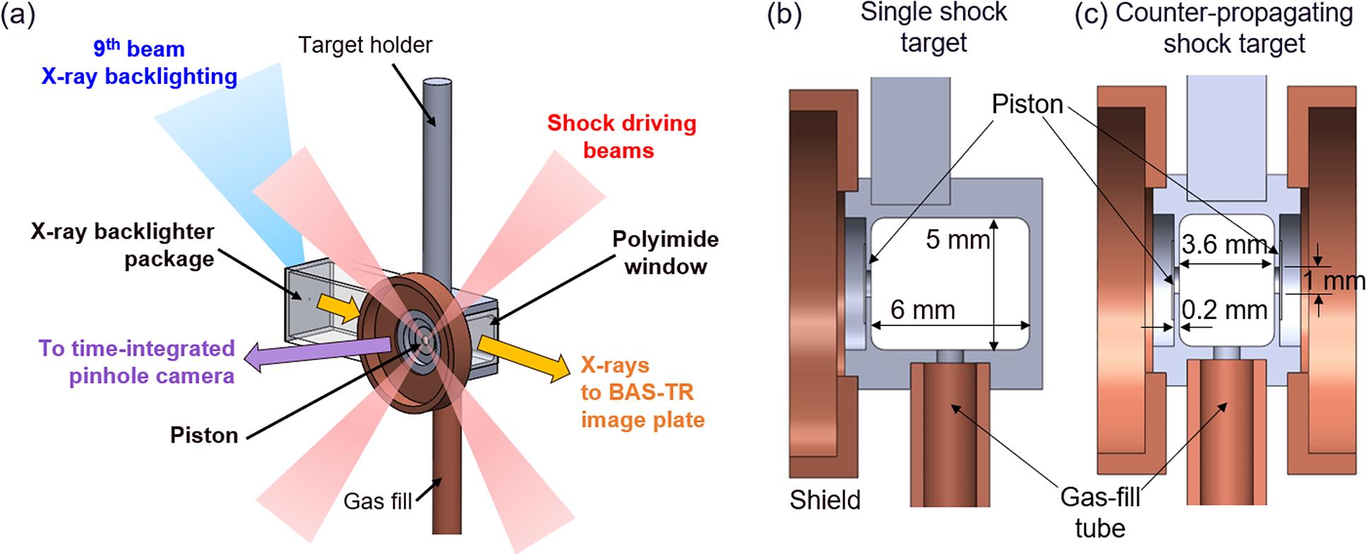
    Fig. 1. (a) Schematic diagram of the experimental setup for a single shock target on the SG-II laser, with a similar configuration used for counter-propagating shocks. (b), (c) Cross-sections of single and counter-propagating shock targets.
    (a)–(c) View of the piston: (a) X-ray emission from the laser–piston interaction from a time-integrated pinhole camera diagnostic; (b) microscope image of the 1 mm diameter shock aperture and CH–Br/CH pistons; (c) lineout of (a) and Gaussian fit to estimate the laser spot size. (d), (e) Target view: field of view of the X-ray backlighting diagnostic of a single shock target and example of raw X-ray image result, respectively.
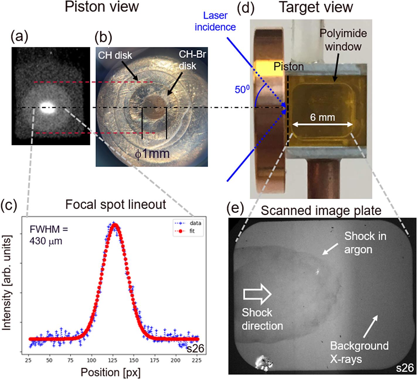
    Fig. 2. (a)–(c) View of the piston: (a) X-ray emission from the laser–piston interaction from a time-integrated pinhole camera diagnostic; (b) microscope image of the 1 mm diameter shock aperture and CH–Br/CH pistons; (c) lineout of (a) and Gaussian fit to estimate the laser spot size. (d), (e) Target view: field of view of the X-ray backlighting diagnostic of a single shock target and example of raw X-ray image result, respectively.
    XRBL results for (a) single and (b) colliding shocks. Artefacts from hard X-ray background (see Figure 2(e)) have been removed for visual purposes. For colliding shocks, the position is taken relative to the left-hand side piston and the vertical arrows mark the approximate position of the shock fronts in each frame. The arrows suggest that the shocks interpenetrate; however, in reality the experiments are in a collisional regime where no interpenetration occurs.
    Fig. 3. XRBL results for (a) single and (b) colliding shocks. Artefacts from hard X-ray background (see Figure 2(e)) have been removed for visual purposes. For colliding shocks, the position is taken relative to the left-hand side piston and the vertical arrows mark the approximate position of the shock fronts in each frame. The arrows suggest that the shocks interpenetrate; however, in reality the experiments are in a collisional regime where no interpenetration occurs.
    Shock front position as a function of time measured from the results in Figure 3 for single and colliding shocks. For the latter, the positions of the shock fronts are marked in Figure 3(b) with matching colours.
    Fig. 4. Shock front position as a function of time measured from the results in Figure 3 for single and colliding shocks. For the latter, the positions of the shock fronts are marked in Figure 3(b) with matching colours.
    Numerical simulations of the experiments with the 2D radiation hydrodynamics code ARWEN at 20 ns. (a) Maps of mass density and temperature. (b) Axial lineouts (at a radius of 0 mm) of mass density, temperature, materials and ionization from (a).
    Fig. 5. Numerical simulations of the experiments with the 2D radiation hydrodynamics code ARWEN at 20 ns. (a) Maps of mass density and temperature. (b) Axial lineouts (at a radius of 0 mm) of mass density, temperature, materials and ionization from (a).
    Francisco Suzuki-Vidal, Thomas Clayson, Chantal Stehlé, Uddhab Chaulagain, Jack W. D. Halliday, Mingying Sun, Lei Ren, Ning Kang, Huiya Liu, Baoqiang Zhu, Jianqiang Zhu, Carolina De Almeida Rossi, Teodora Mihailescu, Pedro Velarde, Manuel Cotelo, John M. Foster, Colin N. Danson, Christopher Spindloe, Jeremy P. Chittenden, Carolyn Kuranz. First radiative shock experiments on the SG-II laser[J]. High Power Laser Science and Engineering, 2021, 9(2): 02000e27
    Download Citation