
Francisco Suzuki-Vidal, Thomas Clayson, Chantal Stehlé, Uddhab Chaulagain, Jack W. D. Halliday, Mingying Sun, Lei Ren, Ning Kang, Huiya Liu, Baoqiang Zhu, Jianqiang Zhu, Carolina De Almeida Rossi, Teodora Mihailescu, Pedro Velarde, Manuel Cotelo, John M. Foster, Colin N. Danson, Christopher Spindloe, Jeremy P. Chittenden, Carolyn Kuranz. First radiative shock experiments on the SG-II laser[J]. High Power Laser Science and Engineering, 2021, 9(2): 02000e27
- High Power Laser Science and Engineering
- Vol. 9, Issue 2, 02000e27 (2021)
Abstract
Keywords
1 Introduction
Radiative shocks are formed when radiative losses from the shock can modify its structure. This occurs when the radiative energy flux is comparable to the kinetic energy flux at the shock front. In this regime, radiation can modify both the pre- and post-shock regions. Radiative effects increase with the shock speed due to stronger post-shock heating and, in a first approximation for typical experimental conditions, radiative effects start playing a role at shock velocities of tens to hundreds of kilometres per second and gas pressures of
Recent works have looked at bridging the gap between experiments and theory/numerical simulations of radiative shocks[3] and applications to astrophysics[4]. In particular, recent experiments have looked at the interaction of a piston-driven shock with an obstacle[5,6]. However, several issues have led to difficulties making a complete bridge between simulations and experiments, for instance, the question of opacity for heavy gases (e.g., xenon) or the nature of the rise of instabilities and the role played by radiation. In addition, at higher velocity, temperature increases strongly and non-local thermodynamic equilibrium (non-LTE) effects start to play a role[7]. It is, therefore, of key importance to continue experimental efforts to obtain more experimental data to be compared with theoretical works.
The experiments presented here use the Shenguang-II (SG-II) laser to drive shocks via piston action from a foil attached to one of the ends of a gas-cell target. Although the SG-II laser has been operational for many years, future improvements planned for this facility in the coming years make these first experiments critical for planning and testing future experimental campaigns.
Sign up for High Power Laser Science and Engineering TOC. Get the latest issue of High Power Laser Science and Engineering delivered right to you!Sign up now
The targets are characterized by a large internal volume and field of view to probe the dynamics of the shock as a function of time without any shock–wall interactions. This configuration is similar to the first experiments performed on the Orion laser, where shocks were driven in xenon[8] and neon[
2 Experimental setup
The SG-II laser[10] can drive up to eight beams with a pulse duration of 1 ns in two opposite directed groups of four beams. Thus, 4–8 beams were used depending on whether the experiment was aimed at producing single or counter-propagating shocks. The overall experimental setup is shown schematically in Figure 1(a) for a single shock target. The targets are similar for the case of counter-propagating shocks, where four additional beams are focused on a second piston placed opposite to the first. Detailed dimensions for both types of targets are shown in Figures 1(b) and 1(c).
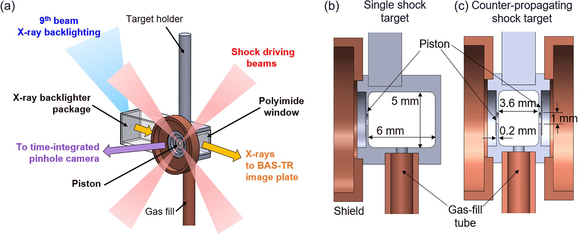
Figure 1.(a) Schematic diagram of the experimental setup for a single shock target on the SG-II laser, with a similar configuration used for counter-propagating shocks. (b), (c) Cross-sections of single and counter-propagating shock targets.
The lasers driving each shock had a total energy of
![]()
Figure 2.(a)–(c) View of the piston: (a) X-ray emission from the laser–piston interaction from a time-integrated pinhole camera diagnostic; (b) microscope image of the 1 mm diameter shock aperture and CH–Br/CH pistons; (c) lineout of (a) and Gaussian fit to estimate the laser spot size. (d), (e) Target view: field of view of the X-ray backlighting diagnostic of a single shock target and example of raw X-ray image result, respectively.
2.1 Target design
Gas-cell targets were designed for SG-II with two main purposes: (1) to provide a large ambient gas volume to allow the shocks to propagate without being subject to radiative or hydrodynamic interactions with the gas-cell walls; and (2) to maximize the XRBL diagnostic field of view in order to follow the evolution of the shocks for times up to 100 ns.
Two target designs (Figure 1(b)) were fielded on SG-II: a single shock target with a diagnostic window size (width
The targets for SG-II were designed based on previous experiments on the Orion laser[11], with several improvements implemented for SG-II: (1) a thinner, 0.2 mm thick frame between the piston and the edge of the diagnostic window to probe the early-time behaviour of the shock (cf. 1 mm for Orion). A drawback of decreasing the frame thickness was that this reduced the shielding that the target provided to prevent hard X-ray emission from the laser–piston interaction from contaminating the signal on the XRBL diagnostic. This meant the level of background noise in diagnostic images from these experiments was higher than the level observed previously on Orion. (2) A smaller, 1 mm diameter aperture for the piston was in contact with the gas (cf. 3–5 mm in Orion) to reduce the ‘swelling’ of the piston with gas-fill pressure inside the vacuum chamber. This helps to achieve a more consistent laser focal spot size during each shot. (3) Lastly, the SG-II targets were gas-filled in situ while inside the vacuum chamber, allowing for a faster shot turnaround and accurate gas-pressure measurement right before each shot. This gas-fill system was also used in previous experiments on the PALS laser[12,13]. For the experiments presented here, argon with an initial gas pressure of
The pistons for SG-II were made with a layer of 30 μm thick CH (on the laser-drive side,
2.2 XRBL diagnostic
A point-projection XRBL package was attached to the side of each target. It consisted of a 5 μm thick, 500 μm diameter scandium foil (a microdot) that was supported on a 100 μm thick tantalum substrate, glued to a 3D-printed acrylic frame that was aligned to the centre of the gas-cell window. The X-ray source size was constrained by a
The backlighter beam average laser parameters were an energy of
The spatial resolution of the XRBL was estimated by illuminating a vanadium grid attached to a target and fitting the resulting spatial profile to the convolution of the ideal point projection from the grid with a Gaussian function. This results in a resolution of
3 Results
Results from single and colliding radiative shock experiments are presented in Figures 3(a) and 3(b), respectively. Each image was obtained from a different shot with similar initial conditions for the laser drive and gas-fill pressure. Overall, the results showed good shot-to-shot reproducibility for the shock dynamics. Average laser-drive parameters in these experiments were an energy of
![]()
Figure 3.XRBL results for (a) single and (b) colliding shocks. Artefacts from hard X-ray background (see Figure 2(e)) have been removed for visual purposes. For colliding shocks, the position is taken relative to the left-hand side piston and the vertical arrows mark the approximate position of the shock fronts in each frame. The arrows suggest that the shocks interpenetrate; however, in reality the experiments are in a collisional regime where no interpenetration occurs.
Dark spots in the images are due to debris reaching the image plate, which appears to be more pronounced in the case of colliding shocks. The XRBL results were characterized by vertical bands with abrupt changes in X-ray intensity that are attributed to background X-ray emission coming from the laser–piston interaction (see the right-hand side of Figure 2(e)). These artefacts were removed from the images in Figure 3 by subtracting the average intensity distribution from regions where the shock was not present. Future experiments will look at reducing debris and background emission on the image plate by adding extra shielding on the targets.
Figure 3(a) shows the results for a single shock for times between 20 and 100 ns, with each image corresponding to a separate experiment with nominally identical initial conditions. The shocks show a semi-hemispherical shape with a good degree of axial symmetry (i.e., with respect to a height of 0 mm in the window). In the earliest image, at 20 ns, the shock front is seen as a fairly smooth feature; however, from 40 ns onwards the shock develops spatial nonuniformities that grow in size as time increases. Rough wavelengths of these features are
Figure 3(b) shows the results for two colliding shocks in a counter-propagating configuration. Before and after the collision, the two shocks show a good degree of left–right symmetry and thus demonstrate a well-controlled laser drive and a consistent target fabrication procedure. These results show similar dynamics to previous experiments on the Orion laser using xenon at the same initial gas mass density (
Figure 4 shows the position of the tip of the shock fronts with respect to the initial position of the piston for single and colliding shocks, measured from the data shown in Figure 3. For visual purposes, the position of the shocks is marked at 40, 50 and 60 ns, as if the shocks interpenetrated; however, the argon plasma in the shocks is expected to be in the collisional regime as the ion mean free path of argon is
![]()
Figure 4.Shock front position as a function of time measured from the results in
To complement the experimental results, preliminary numerical simulations of the experiments are presented in Figure 3 for a single shock at 20 ns. The simulations were performed with the 2D radiative hydrodynamics code ARWEN[19,20]. A full comparison with the experimental data requires further testing of these simulations with several initial conditions; thus, this single output is used to infer characteristic plasma conditions and make first estimates, and further work will look at presenting a detailed simulation study. These first simulations were obtained using the initial conditions in the experiments, that is, an initial argon pressure of
Figure 5 shows 2D maps of mass density and temperature together with axial (at a radius of r = 0 mm) lineouts of these quantities and materials and ionization. The profiles of density, temperature and ionization are representative of the typical structure of a radiative shock: a sharp jump in temperature and density at the shock front position (shown as a vertical dashed line at
![]()
Figure 5.Numerical simulations of the experiments with the 2D radiation hydrodynamics code ARWEN at 20 ns. (a) Maps of mass density and temperature. (b) Axial lineouts (at a radius of 0 mm) of mass density, temperature, materials and ionization from (a).
4 Discussion and conclusions
We have presented the first results from experiments looking at the formation of radiative shocks in argon with piston-driven gas cells on the SG-II laser. The main diagnostic fielded was point-projection XRBL which, combined with a new gas-cell design, allowed the study of shock evolution for single and counter-propagating colliding shocks. In the case of colliding shocks, the results are similar to previous experiments using the Orion laser, demonstrating the feasibility of this platform on SG-II to carry out future experiments of this type. The study of the post-shock region in single shocks had not been looked at in detail in previous experiments (e.g., on Orion and other similar laser facilities). For instance, work in Ref. [5] and references therein have mostly focused on the radiative precursor region ahead of the shock and rarely studied the dense post-shock region.
One of the main results of these experiments on SG-II was to study the morphology of a single shock up to 100 ns to understand its evolution. The shock is characterized by the growth of spatial nonuniformities, with typical wavelengths
We can estimate characteristic time scales for the growth of hydrodynamic instabilities from a shocked-clump model presented in Ref. [21]. For a strong shock, the Rayleigh–Taylor instability is expected to grow in a time scale given by
The role of radiative cooling in the shock can be estimated using the plasma parameters from the simulations of
The use of argon at a relatively high initial pressure (1 bar) and the resulting shock velocity of
Future work on SG-II will aim at providing more statistics of single shocks in argon and assess the role of radiative losses in the formation of these features. This will be complemented by a more detailed simulation work with the ARWEN code.
References
[1] R. P. Drake. High Energy Density Laboratory Astrophysics(2005).
[2] R. P. Drake. Nucl. Fusion, 59, 035001(2019).
[3] P. Mabey, T. Michel, B. Albertazzi, E. Falize, N. Charpentier, M. Koenig. Phys. Plasmas, 27, 083302(2020).
[4] P. Mabey, B. Albertazzi, G. Rigon, J. R. Marqués, C. A. J. Palmer, J. Topp-Mugglestone, P. Perez-Martin, F. Kroll, F. E. Brack, T. E. Cowan, U. Schramm, K. Falk, G. Gregori, E. Falize, M. Koenig. Astrophys. J, 896, 167(2020).
[5] T. Michel, E. Falize, B. Albertazzi, G. Rigon, Y. Sakawa, T. Sano, H. Shimogawara, R. Kumar, T. Morita, C. Michaut, A. Casner, P. Barroso, P. Mabey, Y. Kuramitsu, S. Laffite, L. Van Box Som, G. Gregori, R. Kodama, N. Ozaki, P. Tzeferacos, D. Lamb, M. Koenig. High Power Laser Sci. Eng., 6, e30(2018).
[6] T. Michel, B. Albertazzi, P. Mabey, G. Rigon, F. Lefevre, L. V. B. Som, P. Barroso, S. Egashira, R. Kumar, C. Michaut, M. Ota, N. Ozaki, Y. Sakawa, T. Sano, E. Falize, M. Koenig. Astrophys. J, 888, 25(2019).
[7] R. Rodríguez, G. Espinosa, J. M. Gil, C. Stehlé, F. Suzuki-Vidal, J. G. Rubiano, P. Martel, E. Mínguez. Phys. Rev. E, 91, 053106(2015).
[8] F. Suzuki-Vidal, T. Clayson, C. Stehlé, G. F. Swadling, J. M. Foster, J. Skidmore, P. Graham, G. C. Burdiak, S. V. Lebedev, U. Chaulagain, R. L. Singh, E. T. Gumbrell, S. Patankar, C. Spindloe, J. Larour, M. Kozlová, R. Rodriguez, J. M. Gil, G. Espinosa, P. Velarde, C. Danson. Phys. Rev. Lett., 119, 055001(2017).
[9] T. Clayson, F. Suzuki-Vidal, S. V. Lebedev, G. F. Swadling, C. Stehlé, G. C. Burdiak, J. M. Foster, J. Skidmore, P. Graham, E. Gumbrell, S. Patankar, C. Spindloe, U. Chaulagain, M. Kozlová, J. Larour, R. L. Singh, R. Rodriguez, J. M. Gil, G. Espinosa, P. Velarde, C. Danson. High Energy Density Phys., 23, 60(2017).
[10] J. Zhu, J. Zhu, X. Li, B. Zhu, W. Ma, X. Lu, W. Fan, Z. Liu, S. Zhou, G. Xu, G. Zhang, X. Xie, L. Yang, J. Wang, X. Ouyang, L. Wang, D. Li, P. Yang, Q. Fan, M. Sun, C. Liu, D. Liu, Y. Zhang, H. Tao, M. Sun, P. Zhu, B. Wang, Z. Jiao, L. Ren, D. Liu, X. Jiao, H. Huang, Z. Lin. High Power Laser Sci. Eng., 6, e55(2018).
[11] C. Spindloe, D. Wyatt, S. Astbury, G. F. Swadling, T. Clayson, C. Stehlé, J. M. Foster, E. Gumbrell, R. Charles, C. N. Danson, P. Brummitt, F. Suzuki-Vidal. High Power Laser Sci. Eng., 5, e22(2017).
[12] U. Chaulagain, C. Stehl, J. Larour, M. Kozlov, F. Suzuki-Vidal, P. Barroso, M. Cotelo, P. Velarde, R. Rodriguez, J. Gil, A. Ciardi, O. Acef, J. Nejdl, L. de S, R. Singh, L. Ibgui, N. Champion. High Energy Density Phys., 17, 106(2015).
[13] R. Singh, C. Stehl, F. Suzuki-Vidal, M. Kozlová, J. Larour, U. Chaulagain, T. Clayson, R. Rodriguez, J. Gil, J. Nejdl, M. Krus, J. Dostal, R. Dudzak, P. Barroso, O. Acef, M. Cotelo, P. Velarde. High Energy Density Phys., 23, 20(2017).
[14] C. C. Kuranz, B. E. Blue, R. P. Drake, H. F. Robey, J. F. Hansen, J. P. Knauer, M. J. Grosskopf, C. Krauland, D. C. Marion. Rev. Sci. Instrum., 77, 10E327(2006).
[15] L. E. Ruggles, J. L. Porter, P. K. Rambo, W. W. Simpson, M. F. Vargas, G. R. Bennett, I. C. Smith. Rev. Sci. Instrum., 74, 2206(2003).
[16] D. Sinars, L. Gregorian, D. Hammer, Y. Maron. Proc. IEEE, 92, 1110(2004).
[17] H.-S. Park, D. Ryutov, J. Ross, N. Kugland, S. Glenzer, C. Plechaty, S. Pollaine, B. Remington, A. Spitkovsky, L. Gargate, G. Gregori, A. Bell, C. Murphy, Y. Sakawa, Y. Kuramitsu, T. Morita, H. Takabe, D. Froula, G. Fiksel, F. Miniati, M. Koenig, A. Ravasio, A. Pelka, E. Liang, N. Woolsey, C. Kuranz, R. Drake, M. Grosskopf. High Energy Density Phys., 8, 38(2012).
[18] G. Espinosa, R. R. dríguez, J. M. Gil, F. Suzuki-Vidal, S. V. Lebedev, A. Ciardi, J. G. Rubiano, P. Martel. Phys. Rev. E, 95, 033201(2017).
[19] F. Ogando, P. Velarde, J. Quant. Spectrosc. Radiat. Transf., 71, 541(2001).
[20] D. García-Senz, P. Velarde, F. Suzuki-Vidal, C. Stehlé, M. Cotelo, D. Portillo, T. Plewa, A. Pak. Astrophys. J, 871, 177(2019).
[21] E. C. Hansen, A. Frank, P. Hartigan, S. V. Lebedev. Astrophys. J, 837, 143(2017).
[22] B. Loupias, C. D. Gregory, E. Falize, J. Waugh, D. Seiichi, S. Pikuz, Y. Kuramitsu, A. Ravasio, S. Bouquet, C. Michaut, P. Barroso, M. Rabec le Gloahec, W. Nazarov, H. Takabe, Y. Sakawa, N. Woolsey, M. Koenig. Astrophys. Space Sci., 322, 25(2009).
[23] A. J. Visco, R. P. Drake, S. H. Glenzer, T. Döppner, G. Gregori, D. H. Froula, M. J. Grosskopf. Phys. Rev. Lett., 108, 145001(2012).
[24] A. B. Reighard, R. P. Drake, T. Donajkowski, M. Grosskopf, K. K. Dannenberg, D. Froula, S. Glenzer, J. S. Ross, J. Edwards. Rev. Sci. Instrum, 77, 10E504(2006).
[25] É. Falize, C. Michaut, S. Bouquet. Astrophys. J., 730, 96(2011).
[26] A. Dizière, C. Michaut, M. Koenig, C. D. Gregory, A. Ravasio, Y. Sakawa, Y. Kuramitsu, T. Morita, T. Ide, H. Tanji, H. Takabe, P. Barroso, J. M. Boudenne. Astrophys. Space Sci., 336, 213(2011).

Set citation alerts for the article
Please enter your email address
© Copyright 2018-2021 | Chinese Laser Press. All Rights Reserved 沪ICP备15018463号-20