• Journal of Infrared and Millimeter Waves
  • Vol. 39, Issue 2, 228 (2020)
Qin-Qin WU1, Xi-Cai LI1, Yuan-Qing WANG1、2、*, and Shu-Ping REN3
Author Affiliations
  • 1School of Electronic Science and Engineering, Nanjing University, Nanjing20023, China
  • 2Key Laboratory of Intelligent Optical Sensing and Manipulation, Ministry of Education,Nanjing University, Nanjing1003, China
  • 3JiangXi Academy of Sciences, Nanchang0000, China.
  • show less
    DOI: 10.11972/j.issn.1001-9014.2020.02.010 Cite this Article
    Qin-Qin WU, Xi-Cai LI, Yuan-Qing WANG, Shu-Ping REN. Human localization technology based on the pyroelectric infrared sensors[J]. Journal of Infrared and Millimeter Waves, 2020, 39(2): 228 Copy Citation Text show less

    Abstract

    A field of views of pyroelectric infrared sensors modulation strategy is proposed. The strategy can improve the human localization resolution, and it will not reduce the detection distance of pyroelectric infrared sensor. For the strategy, the field of views of pyroelectric infrared sensors are modulated by a mask. And the modulated field of views overlap and interleave with each other to form some sampling areas. In order to verify the proposed field of views modulation strategy, the human localization node which includes nine pyroelectric infrared sensors is fabricated. The modulated degree of the field of views of each pyroelectric infrared sensor is 36°. The degree of each sampling area is 4°. If the human moves in a sampling area, the corresponding pyroelectric infrared sensors will be triggered. The human position can be localized by using at least two nodes. According to the states of the pyroelectric infrared sensors, the human position can be estimated. In the experiment, two nodes are set in a 600 cm × 600 cm square area, the theoretical error is analyzed by using least square estimation. The theoretical maximum error of the two nodes human localization equipment in a 600 cm×600 cm square area is about 70 cm. Eight human positions are estimated in experiments, and the estimation route is formed by connecting all the estimated positions. The estimation route is close to the predefined route. The minimum and maximum estimation errors are about 4.42 cm and 16.91 cm respectively.

    Introduction

    Human tracking and localization technology is one of most significant topic for the security [1] and machine vision [2]. Researchers have done a lot of work for the human localization and tracking. There are some kinds of strategy for human tracking and localization. The first strategy utilizes vision device to detect the target, such as visible-light camera and near-infrared camera [3]. The visible-light camera and near-infrared camera can quick and precise to find targets based on the computer vision and digital image processing techniques [4]. But the environment factors such as high light background or weak light condition will affect the detection. And not all occasions are suitable for installation of camera, such as bedroom or toilet. In addition, the near-infrared camera need to use the near infrared source for illumination. The detection range of near-infrared camera is limited by the limitation of source illumination range. The second strategy is based on wearable device. This method requires target human to wear a device on his glasses or collar, such as near-infrared led. And this method uses a detector such as position sensitive device (PSD) to track the wearable device [5]. However, the power unit for the wearable device cannot work for a long time, and the wearable device will lead to discomfort. The dense sensing based activity monitoring is the third strategy, such as environment state-change sensors [6], break-beam sensors, pressure mats, contact switches [7], microphones and pyroelectric infrared sensors. The dense sensing is suitable for intelligent environment enabled applications [8].

    Pyroelectric infrared sensors (PIR) [9,10,11] received extensive attention due to the low cost, low power consumption and excellent performances. The PIR can detect the mid-infrared light (8~14 μm) emitted by human body. Thus, the PIR can detect the human body without any help of other light source, and the human body doesn’t need to equip any device. Furthermore, the detection based on the PIR doesn’t belong to the imaging detection. Thus, it won’t invade human privacy. It is suitable for most occasions. And the PIR only can be triggered by the dynamic changed light. The invariable light or heater in the field of views (FOVs) cannot trigger the sensor. Thus, the localization system composed by PIRs can avoid disturbances caused by the obstacles.

    In this paper, a FOV modulation strategy is proposed, and the human localization node based on the proposed strategy is fabricated. The proposed FOVs modulation strategy can improve the human localization resolution without reduction of the detection distance of the PIR. Owing to larger angle of modulated FOV and smaller angle of sampling area (SA), the modulation strategy can achieve larger theoretical detection distance and higher angle resolution compare with the strategies which are reported in [12,13,14]. For our node, the angle of the modulated FOV of each PIR is 36°, and the angle of each SA is 4°. We use two nodes to localize the human position in a 600 cm×600 cm square area, and the theoretical error is analyzed. The maximum theoretical error is about 70 cm. For the experiment, the minimum and maximum localization errors are about 4.42 cm and 16.91cm respectively.

    1 The principle of human localization by use of PIR

    PIR is a frequently-used human body detection device. It is sensitive to 8~14 µm infrared light. The Fresnel lens can enhance the detection distance of PIR. If a human walks in the FOV of the PIR, the PIR will be triggered and output analog signal. Process the signal to determine the state of the PIR. Use the ‘0’ and ‘1’ (two states) to represent the PIRs are triggered or not [13,15]. According the states of the PIRs, the position of the human can be estimated. Some papers have been reported that use the PIRs to localize human position. In Ref.12, fourteen separate masks are used to modulate the FOVs of fourteen PIRs,the angle of the SA for each PIR is set to 5°, the sketch map of the modulation strategy can be seen in Fig.1(a). In Refs.13-14, researchers use a mask to modulate the FOV of one PIR. The modulation strategy is shown in Fig.1(b).

    The sketch map of the modulation strategy of Ref.12 and Refs.13-14 (a) The modulation strategy of Ref.12,(b) the modulation strategy of Refs.13-14

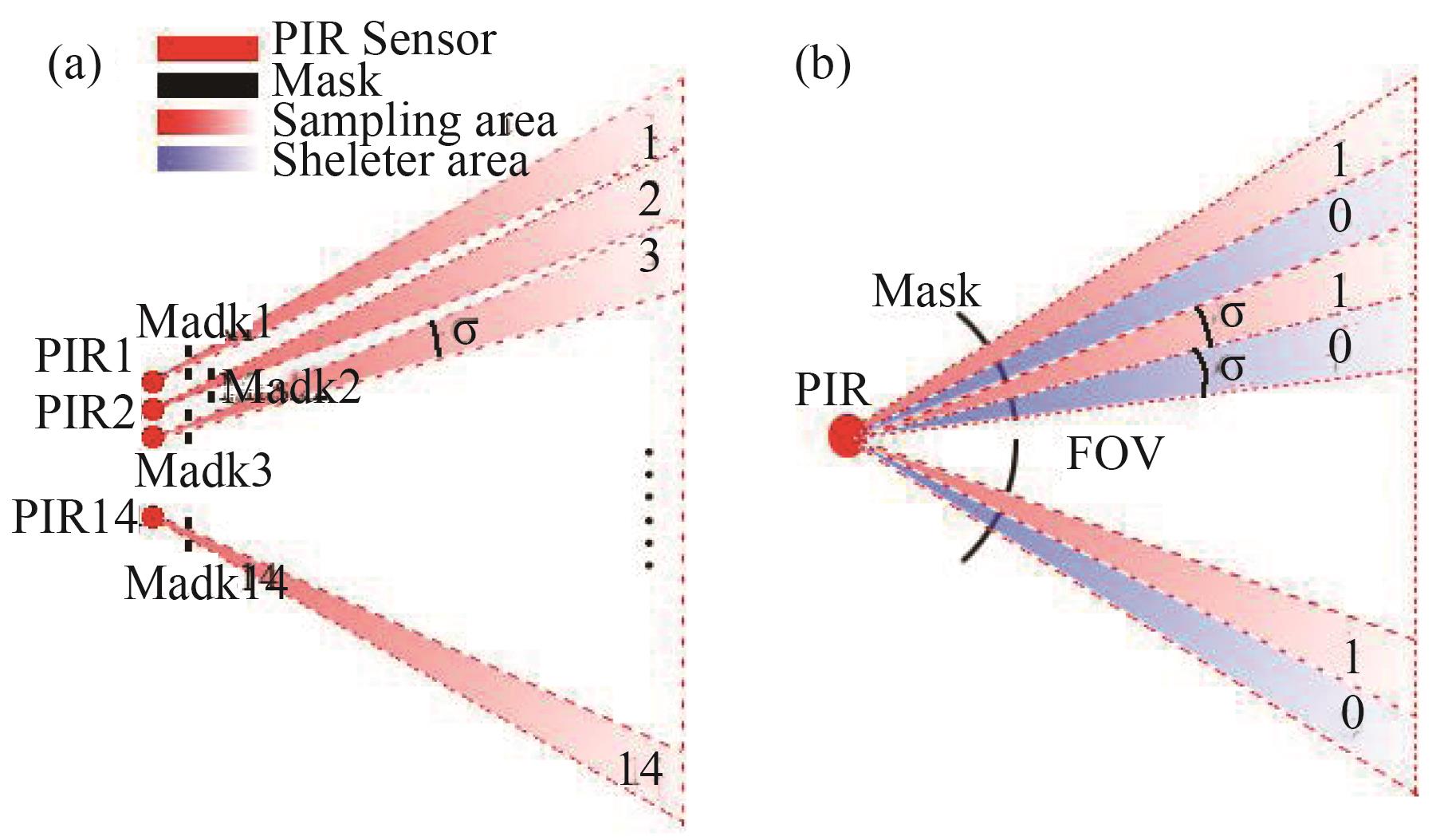
    Figure 1.The sketch map of the modulation strategy of Ref.12 and Refs.13-14 (a) The modulation strategy of Ref.12,(b) the modulation strategy of Refs.13-14

    As shown in Fig.1(a-b), the σ represents the angle resolution. Obviously, for these two kinds of modulation strategies, the smaller degree of FOV of PIR is, the higher angle resolution of system can be achieved. However, the smaller degree of FOV is, the less infrared energy the PIR can receive. It will impact the detection distance of the PIR. The sketch map of the proposed FOVs modulation strategy can be seen in Fig.2.

    The sketch map of the proposed FOVs modulation strategy (a) the FOV of one PIR is modulated by a mask, (b) ideally, the starting points of the FOVs of multiple PIRs are located at same point (Q), and the FOVs stagger and overlap with each other to form multiple SAs.

    Figure 2.The sketch map of the proposed FOVs modulation strategy (a) the FOV of one PIR is modulated by a mask, (b) ideally, the starting points of the FOVs of multiple PIRs are located at same point (Q), and the FOVs stagger and overlap with each other to form multiple SAs.

    As shown in Fig.2(a), there is a rectangular window on the mask, and it can modulate the FOV of the PIR. The projection of the modulated FOV on X-Y plane is a fan-shaped. Set the angle of the projection to be γ. In order to achieve human position localization, multiple PIRs should be used. In this paper, we describe the proposed modulation strategy based on the node which includes nine PIRs. The FOVs are labeled as FOVkk=1, 2, 3, ……, K, K=9). The FOVs of PIRs interleave and overlap with each other to form multiple SAs, as shown in Fig.2(b). Ideally, assume that all the PIRs are located at same point (Q). Thus, the starting points of all FOVs are also located at this point.

    Set the angle of the detection area of the node which includes K PIRs to be ψ, as shown in Fig.2(b). The SAs are labeled as Sll=1, 2, 3, ……, L). The angle σ of each SA can be described in Eq.1:

    σ=ψL  

    where L is the total number of SAs. And for the proposed strategy,ψ also can be described as Eq. 2:

    ψ=2γ-σ=2LγL+1

    The relationship between K and L can be described as Eq. 3:

    L=2K-1

    Substitute the Eq. 2 and Eq. 3 into Eq. 1, the σ=γ/K can be obtained. For the proposed modulation strategy, the angle resolution σ is related to γ and K. If the γ is given, we can increase the K to improve the angle resolution, and the γ doesn’t need to be reduced. In order to verify the proposed modulation strategy, the human localization node which include nine PIRs is fabricated, as shown in Fig.3(a) and Fig.3(b). For the node, the γ is equal to 36°, the ψ is equal to 68°, L is equal to 17, the σ is equal to 4°. In addition, for the node and the proposed modulation strategy, the maximum detection distance of each PIR is about 7 m.

    The physical map of the node, and the sketch map of the sampling areas in non-ideal case (a) The arrangement of PIRs, (b) the physical map of whole node, (c) the sketch map of the sampling areas of the node in non-ideal case

    Figure 3.The physical map of the node, and the sketch map of the sampling areas in non-ideal case (a) The arrangement of PIRs, (b) the physical map of whole node, (c) the sketch map of the sampling areas of the node in non-ideal case

    For the node, the PIRs (KP500B, Nisaila. The parameters of the KP500B can be seen in Table. 1) are arranged in 3x3 matrix, the horizontal distance between adjacent PIRs is 3.4cm. The arrangement of PIRs are shown in Fig.3(a). The angle of the original FOV of the PIR with Fresnel lens is about 100°. The nine windows on the mask and the nine PIRs are corresponding one by one. As shown in Fig.3, it is impossible to set all detectors at the same point. The PIR1~PIR3 move 3.4cm toward to left relative to PIR4~PIR6, and the PIR7~PIR9 move 3.4cm toward to right relative to the PIR4~PIR6.As shown in Fig.3(c), if the X axis coordinates of starting points of the FOVs of PIR4~PIR6 are x, the X axis coordinates of starting points of the FOVs of the PIR1~PIR3 and the PIR7~PIR9 are x+3.4 and x-3.4 respectively. Of course, the angles of the FOVs and the SAs remain unchanged despite the movement of FOVs.

    ItemParameters
    Pass Band514 μm
    Transmittance of the filter>75%
    Sensitivity3 300 V/W
    Detectivity1.5×108 cm∙Hz1/2∙W-1
    Noise<200 mV (mVp-p, 25℃)

    Table 1. The parameters of the KP500B

    When human walks into different sampling area, the different combination of ‘0’ and ‘1’ sequence can be got. Thus, the ‘0’ and ‘1’ sequence can indicate which SA the human located in. The codes of SAs are list in Table 2.

    SAThe state of PIRSequence
    123456789
    1100000000100000000
    2110000000110000000
    3111000000111000000
    ………………
    15000000111000000111
    16000000011000000011
    17000000001000000001

    Table 2. The codes scheme of the 17-SAs.

    If the human located in a SA, we can think that the SA is ‘triggered’. Assume a human located in Sl, and only the Sl is ‘triggered’. We can assume that the human is moving at the angular bisector line Al of the Sl. Such as the point P which is locate at Al, as shown in Fig.3(c). The angle θ between the Al and X axis can be described in Eq. 4 [15].

    θ=π-ψ2+ψLl-ψ2L

    It should be noted that there is no case that multiple SAs are triggered simultaneously for the proposed modulation strategy. However, the human body may cover multiple SAs or the human body only covers one SA, and he (she) makes minor motion. In these case, the multiple SAs can take turn to be triggered. Assume these SAs are Sl, Sl+1, ……, Sl+m, we can think that the human is located at the angular bisector line of the area which consists of Sl, Sl+1, ……, Sl+m. The θ can be described in Eq.5:

    θ=π-ψ2+ψLm-ψ2L(m-l+1)

    In order to further verify the proposed modulation strategy. We use the node to localize the human position. At least two nodes are required for localization. Assume that there are two nodes are set in a square area (600 cm×600 cm), as shown in Fig.4. The symmetry axes of the detection areas of the node-1 and node-2 intersect vertically at Q’, and they intersect the X and Y axes at Q1 (300,0) and Q2 (0,300) respectively. The valid localization area of two nodes human localization equipment is colored in lilac.

    Two nodes are used for human localization.

    Figure 4.Two nodes are used for human localization.

    Name the ‘triggered’ SAs Sili=1, 2). The i is the index of nodes. The angle between angular bisector Ail and X axis is named θil. It should be noticed that, the θ1l and θ2l are equal to θ and θ–π/2 respectively, the θ can be calculated by using the Eq. 4 or Eq. 5. According to Fig.3(c), the coordinates of the intersections (xil, yil) of the Ail and X axis or Y axis can be calculated, and they are listed in Table .3.

    The Angular Bisectorxil (cm)yil (cm)
    A11, A12, A1(10), A1(11)300+3.40
    A13, A1(12)300+1.70
    A14, A15, A1(9), A1(13), A1(14)3000
    A16, A1(15)300-1.70
    A17, A18, A1(16), A1(17)300-3.40
    A21, A22, A2(10), A2(11)0300-3.4
    A23, A2(12)0300-1.7
    A24, A25, A29, A2(13), A2(14)0300
    A26, A2(15)0300+1.7
    A27, A28, A2(16), A2(17)0300+3.4

    Table 3. The intersection (xil,yil) of the angular bisector Ail and X axis or Y axis.

    The slopes of the angular bisector Ail are name kil (if the kil is exist), and they can be described in Eq. 6.

    kil=tanθil

    And the expressions of the angular bisectors of the ‘triggered’ SAs can be described in Eq. 7:

    yest-yil=kil(xest-xil)

    where the (xest , yest) is the estimated human position. Substituting the i=1 and i=2 into the Eq. 7. Then the Eq. 8 can be got.

    yest-y1l=k1lxest-x1lyest-y2l=k2lxest-x2l

    The Eq. 8 in matrix form can be described in Eq. 9

    Ap=B

    where p = [xest, yest]T, A and B can be described as follows:

    A=k1l-1k2l-1

     B=k1lx1l-y1lk2lx2l-y2l

    The human position P can be calculated by Eq. 10:

    xest=y2l-y1l+k1lx1l-k2lx2lk1l-k2l yest=k1l(k2lx1l-x2l)+k1ly2l-k2ly1lk1l-k2l

    Substituting the values of kil and the corresponding (xil , yil) which are listed in Table 3 into Eq. 10, the human position can be calculated. In addition, the k1l may not exist. In this case, the xest=x1l = 300. And substitute it into Eq. 8. The yest = y2l+ k2l(300- x2l) can be obtained.

    2 The estimation error analysis

    The errors result from the hypothesis that the human is located at the angular bisector of the ‘triggered’ SA. The estimation human position is (xest , yest). Assuming the errors of xest, yest are Δx, Δy respectively. Thus, the real coordinate of the human position (x , y) can be described in Eq. 11:

    xest=x-xyest=y-y

    Substituting the Eq. 11 into the Eq. 8, the Eq. 12 can be got.

    k1lx-y=k1lx-k1lx1l-y+y1lk2lx-y=k2lx-k2lx2l-y+y2l 

    Set the Δp = [Δx , Δy]T. The matrix form of Eq. 12 is shown in Eq. 13:

    Cp=Δb

    where the C and Δb are described as follows:

    C=k1l-1k2l-1

    Δb=k1lx-k1lx1l-y+y1lk2lx-k2lx2l-y+y2l

    The least square estimation for error can be described in Eq. (14):

    p=(CTC)-1CTΔb

    And if the k1l does not exists, the x1l=300. Thus, the Δx=0, Δy=y-y2l+k2lx2l-k2lx, and it can be simplified to Δy = y- y2l-k2lx.

    According to the formulas mentioned above, the localization error of two nodes human localization equipment can be calculated by using the numerical simulation. The error is shown in Fig.5(a) and Fig.5(b).

    The error analysis of the two nodes human localization equipment (a) Plane diagram of error analysis, (b) 3D diagram of error analysis.

    Figure 5.The error analysis of the two nodes human localization equipment (a) Plane diagram of error analysis, (b) 3D diagram of error analysis.

    It can be seen from Fig.5(a-b), the farther away from two nodes, the larger localization error is. And as shown in Fig.5(a), in the quadrilateral which is formed by intersections of two SAs of two nodes, the farther away from the intersection of the two angular bisectors, the larger localization error is. The maximum theoretical error of the two nodes human localization equipment in 600 cm×600 cm square area is about 70 cm, as shown in Fig.5(b). We only analyze the error in the case that the human only ‘trigger’ one SA of a node, because there is no case that multiple SAs are triggered simultaneously for the proposed modulation strategy. Assume the human locates at the angular bisector line of the area which is consist of multiple SAs, the method of human position localization and error analysis are same with that mentioned above.

    3 Experiment and discussion

    In order to verify the proposed FOVs modulation strategy and the node, the human position localization experiments have been done. According to the setup which is shown in Fig.4, we set two nodes in a 600 cm×600 cm square area, and the coordinates of node-1 and node-2 are (300,0) and (0,300) respectively. Before the experiments, the directions of two nodes should be calibrated to make the symmetry axes of detection areas of two nodes are perpendicular. And they are also perpendicular to the sidelines of the square area. The target human walks along the predefined route on the ground, stop in eight setting positions and do some minor movement. The speed is about 1 m/s. Record the output signals of the PIRs and then determine their states. The states determined processes can be seen in Fig.6.

    The PIR states determined processes (a) the original signal, (b) denoise the signal by using wavelet soft threshold noise reduction method, (c) calculate the absolute values of the signal, (d) smoothing the signal, (e) set a threshold. If the amplitude of the signal larger than the threshold, set the amplitude to ‘1’, else to ‘0’, (f) further optimize the signal to determine the state of the PIR.

    Figure 6.The PIR states determined processes (a) the original signal, (b) denoise the signal by using wavelet soft threshold noise reduction method, (c) calculate the absolute values of the signal, (d) smoothing the signal, (e) set a threshold. If the amplitude of the signal larger than the threshold, set the amplitude to ‘1’, else to ‘0’, (f) further optimize the signal to determine the state of the PIR.

    The original signal of a PIR is shown in Fig.6(a). The signal is denoised by using the wavelet soft threshold noise reduction method. The denoised signal is shown in Fig.6(b). The absolute value of the denoised signal is calculated, as shown in Fig.6(c). But this process can introduce some interference points into the signal. The interference points are emphatic marked by red boxes, as shown in Fig.6(c). In order to reduce the impact of the interference points, the signal should be smoothed, as shown in Fig.6(d). Set a threshold (15% of the maximum of signal). If the amplitude of the signal is larger than the threshold, set the amplitude to ‘1’, else to ‘0’, as shown in Fig.6(e). Some parts of state signal are misjudged due to the small absolute value, and they are marked by the red boxes, as shown in Fig.6(e). Further optimize the signal to determine the final state of the PIR, as shown in Fig.6(f). After the states of all PIRs are determined, the ‘triggered’ SAs can be determined. The recorded ‘triggered’ SAs of two nodes in experiments are shown in Table 4.

    No.Node-1Node-2Real /cmEstimation/cmError/cm
    r1S12~S11S6~S8(250,270)(254.6,266.6)8.09
    r2S10~S9S8~S9(290,290)(293.2,293.2)4.47
    r3S8~S7S9~S10(325,310)(329.0,308.1)4.42
    r4S7~S6S10~S11(365,335)(355.5,334.0)9.57
    r5S6~S5S11~S12(400,370)(392.0,364.9)9.44
    r6S5~S4S12~S13(425,400)(432.5,407.8)10.86
    r7S5~S4S13~S14(450,435)(444.4,444.4)10.94
    r8S4S14~S15(470,480)(479.7,493.8)16.91

    Table 4. The result of the experiment

    It can be seen from the Table 4, multiple SAs are take turn to be ‘triggered’ when the human stands at the setting positions and does some minor motions. The ‘triggered’ SAs of two nodes are listed in 2th and 3th columns of Table 4. According to the ‘triggered’ SAs of the node-1 and node-2, the θ1l and θ2l can be calculated by Eq. 4 or Eq. 5. The slopes k1l, k2l and two straight line expressions can be determined by Eq. 6 and Eq. 8 respectively. The estimation human position is the intersection of these two straight lines. The coordinates of eight setting positions and corresponding estimated positions are listed in 4th and 5th columns of Table 4. The errors are calculated and listed in 7th column of Table 4. It can be seen from the 7th column of Table 4, the minimum and maximum errors are about 4.42 cm and 16.91 cm respectively. The average error is about 9.34 cm. The minimum error 4.42 cm is smaller than 9cm and 32 cm which are reported in Ref.15 and 13 respectively. The maximum error is similar to the maximum error which is reported in Ref.15. The smaller minimum error may be due to the higher angle resolution. The node used in experiment can be seen in Fig.7(a), the height of the node is 130 cm. Connect all the estimated points to form the estimation route. The estimated route and predefined route can be seen in Fig.7(b). The predefined route and estimated route are represented by the red curve and blue curve respectively. It can be seen from the Fig.7(b) that the estimated route is close to the predefined route.

    The pyroelectric infrared human localization node and the experiment result (a) the pyroelectric infrared human localization node, (b) the predefined route and estimated route.

    Figure 7.The pyroelectric infrared human localization node and the experiment result (a) the pyroelectric infrared human localization node, (b) the predefined route and estimated route.

    In practice, some factors can affect the accuracy of human localization by using PIRs. For example, the other heating sources in FOV, human body temperature and so on. The dynamic infrared source, such as the moving animal, the air conditioner at working, head shaking heating system and the flying curtains, can affect the localization. Commonly, the pyroelectric signals caused by above heaters are different with that of human. The interference signals can be filtered by suitable filter. And the pattern recognition algorithms can be used to recognize whether the heater is human or not [16,17]. The temperature of body can also affect the detection of the PIR. The human body temperature is generally maintained at about 36°C. But it may change drastically after the human stay in cold or hot condition for a long time. Owing to the weaker pyroelectric signal, low body temperature may lead to incorrect localization. The high human body temperature doesn’t affect the localization. And the problems caused by the body temperature may go away quickly once the body returns to a normal temperature[18]. Furthermore, the proposed method only can localize one human at one time. We are researching more advanced algorithms to enable the localization system to support multi-objective localization simultaneously.

    4 Conclusion

    In this paper, a field of views of pyroelectric infrared sensors modulation strategy is proposed. For the strategy, the angle resolution is related to the angle of FOV of localization system and the number of the PIRs. The proposed FOVs modulation strategy can improve the angle resolution without reduction of the detection distance of PIR. The theoretical localization error also be analyzed by using the least square estimation. The errors result from the hypothesis that the human is located at the angular bisector of the ‘triggered’ SA. In order to verify the proposed strategy. The human localization node which include nine PIRs is fabricated. The degrees of each SA, the FOV of each PIR and the detection area of the node are 4°, 36° and 68° respectively. The maximum theoretical error of the two nodes localization equipment in 600 cm×600 cm square area is about 70 cm. According to the state sequences of PIRs of the nodes, the target human position can be estimated. We set two nodes in a 600 cm×600 cm square area, and do the localization experiments. Eight positions are estimated. The minimum and maximum errors are about 4.42 cm and 16.91 cm respectively. The estimation route is close to the predefined route. The detection distance of the node is about 7 m. The experiment result indicates that the proposed FOVs modulation strategy is valid.

    Acknowledge

    This work supported by the National Key R&D plan (2016YFB0401500), R&D plan of Jiangsu science and technology department (BE2016173) and program B for outstanding PhD candidate of Nanjing University.

    References

    [1] P Chodon, D M Adhikari, G C Nepal. Passive infrared (PIR) sensor based security system. Electronics & Computer System, 14, 1-5(2013).

    [2] G D Feng, X M Guo, G L Wang. Sensors and Actuators A: Physical, 186, 1-7(2012).

    [3] M Chowdhury, J B Gao, R Islam. Robust human detection and localization in security applications. Concurrency and Computation-Practice & Experience, 29, e3977(2017).

    [4] P Kakumanu, S Makrogiannis, N Bourbakis. A survey of skin-color modeling and detection methods. Pattern Recognition, 40, 1106-1122(2007).

    [5] G C M Meijer, J Vandrecht, P C Dejong. New concepts for smart signal processors and their application to PSD displacement transducers. Sensors and Actuators A: Physical, 35, 23-30(1992).

    [6] E M Tapia, S S Intille, K Larson. Activity recognition in the home using simple and ubiquitous sensors, 3001, 158-175(2004).

    [7] D H Wilson, C Atkeson. binary sensor. Proceedings, 3468, 62-79(2005).

    [8] L Chen, J Hoey, C D Nugent. Sensor-based activity recognition. IEEE Transactions on Systems Man and Cybernetics Part C-Applications and Reviews, 42, 790-808(2012).

    [9] X Y Sun, W B Luo, J Meng. Monolithic pyroelectric infrared detectors using SiO2 aerogel thin films. Sensors and Actuators A: Physical, 228, 69-74(2015).

    [10] Q Q Wu, Y Q Wang, S P Ren. Low cost and anti-noise infrared device based on saw-tooth thermal isolation structure. Sensors and Actuators A: Physical, 266, 178-184(2017).

    [11] W B Luo, Q Q Wu, C G Wu. Pb(ZrTi)0.98Mn0.02O3 weight ratio effects on the properties of Pb(ZrTi)0.98Mn0.02O3/P(VDF-TrFE) compostie film and infrared detectors. Journal of Materials Science: Materials in Electronics, 28, 3474-3480(2017).

    [12] W C Zhou, F M Li, D Li. A human body positioning system with pyroelectric infrared sensor. International Journal of Sensor Networks, 21, 108-115(2016).

    [13] L Jiang, T Zhang, F He, et al. on sensor selection and calibration. IEEE Transactions on Systems Man Cybernetics-Systems, 47, 263-275(2017).

    [14] M Shankar, J B Burchett, Q Hao. Human-tracking systems using pyroelectric infrared detectors. Optical Engineering, 45, 106401(2006).

    [15] G D Feng, X M Guo, G L Wang. Infrared motion sensing system for human-following robots. Sensors and Actuators A: Physical, 185, 11-7(2012).

    [16] W G Gong, K Wen, L F He. Human and Nonhuman Recognition Using Pyroelectric Infrared Detector. International Journal of Thermophysics, 33, 2237-2241(2012).

    [17] J D Zhao, W G Gong, Y Z Tang. EMD-based symbolic dynamic analysis for the recognition of human and nonhuman pyroelectric infrared signals. Sensors, 16, 126.

    [18] J Gong, Y Zhang, X Zhou. Pyro: Thumb-tip gesture recognition using pyroelectric infrared sensing, 553-563(2017).

    Qin-Qin WU, Xi-Cai LI, Yuan-Qing WANG, Shu-Ping REN. Human localization technology based on the pyroelectric infrared sensors[J]. Journal of Infrared and Millimeter Waves, 2020, 39(2): 228
    Download Citation