
Yiqun Zhang, Mingfeng Xu, Mingbo Pu, Mengjie Zhou, Jiazheng Ding, Shuangcheng Chen, Kun Qiu, Ning Jiang, Xiangang Luo, "Simultaneously enhancing capacity and security in free-space optical chaotic communication utilizing orbital angular momentum," Photonics Res. 11, 2185 (2023)
- Photonics Research
- Vol. 11, Issue 12, 2185 (2023)
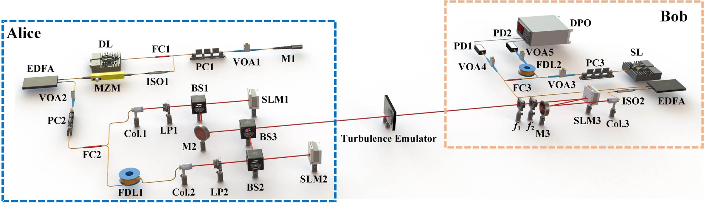
Fig. 1. Experimental setup of the secure chaos-based OAM multiplexing FSO communication system. DL, drive laser; FC, fiber coupler; PC, polarization controller; VOA, variable optical attenuator; M, mirror; ISO, optical isolator; MZM, Mach–Zehnder modulator; EDFA, erbium-doped fiber amplifier; FDL, fiber delay line; Col., collimator; LP, linear polarizer; BS, beam splitter; SLM, spatial light modulator; SL, slave laser; PD, photodetector; DPO, digital phosphor oscilloscope.
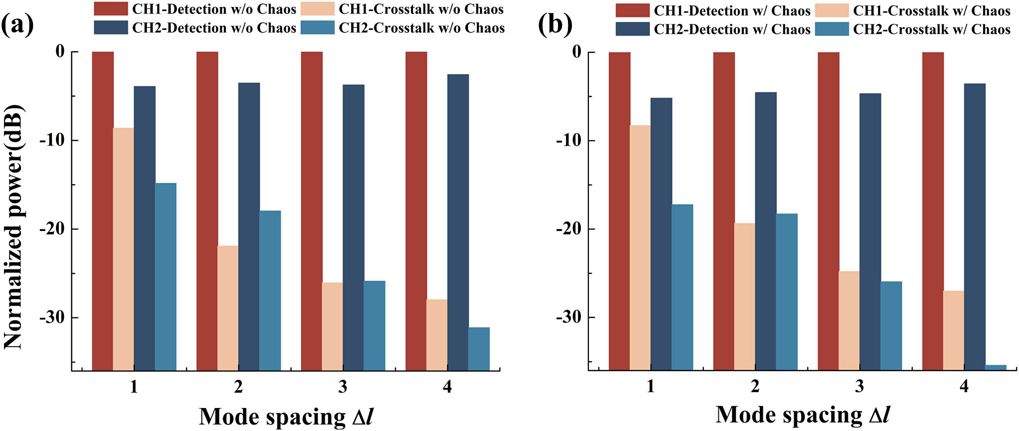
Fig. 2. Measured channel crosstalk for the two OAM modes (a) without chaos feedback loop and (b) with chaos feedback loop. Take mode spacing Δ l = 1 OAM + 2 OAM − 2 OAM + 1 OAM − 2
Fig. 3. (a) Measured chaotic synchronization channel crosstalk for the two OAM modes; (b) cross-correlation plot for CH1 when Δ l = 4 Δ l = 4
Fig. 4. Performance of the chaos-based OAM multiplexing FSO communication system with different mode spacing. (a) Measured BER curves for different mode spacing for CH2 in the case of direct detection. Take mode spacing Δ l = 1 OAM + 2 OAM + 1 OAM − 1 R = 8 Gbps Δ l = 1 Δ l = 2 Δ l = 3 Δ l = 4
Fig. 5. Experimental temporal waveforms for CH2 of (a) the original NRZ-OOK signal at the output of AWG, (b) the encrypted signal at the output of MZM, and (c) the decrypted signal after offline DSP. Eye diagrams of (d) the original NRZ-OOK signal, (e) the encrypted signal, and (f) the decrypted signal. (g) BER performances for CH1 and CH2 in the case of legal reception, illegal reception, and encryption.
Fig. 6. Measured BER curves for different cases as a function of masking coefficient β
Fig. 7. (a1)–(a3) Intensity profiles of demodulated beams for different loading patterns (l = − 3 l = − 2 l = + 3 l = − 3 + 1 R = 10 Gbps
Fig. 8. Measured BER as a function of the percentage of beam block for secure chaos-based OAM multiplexing FSO transmission link. Insets (I) to (III) show the phase holograms partially blocked in SLM3.
Fig. 9. Intensity profiles of (a1)–(a3) generated OAM beams (l = − 3 l = + 1 l = − 3 + 1 l = − 3 l = + 1 l = − 3 + 1 l = − 3 l = + 1 l = − 3 + 1
Fig. 10. Measured chaotic synchronization channel crosstalk matrix (a) without turbulence; (b) with turbulence. (c) BER performance for CH1 and CH2 as a function of bit rate R
|
Table 1. Secure Data Transmission of Chaos-Based FSO Experimental Systems


Set citation alerts for the article
Please enter your email address

© Copyright 2018-2021 | Chinese Laser Press. All Rights Reserved 沪ICP备15018463号-20