
Yulong Cui, Wei Huang, Zhiyue Zhou, Hao Li, Meng Wang, Zilun Chen, Zefeng Wang, "Highly efficient and stable coupling of kilowatt-level continuous wave laser into hollow-core fibers," Chin. Opt. Lett. 20, 040602 (2022)
- Chinese Optics Letters
- Vol. 20, Issue 4, 040602 (2022)
Abstract
1. Introduction
Different from the solid-state fiber using total reflection, the hollow-core fiber (HCF) can confine light into the hollow core with 10 to 100 µm diameters due to its special cladding structure, and it can also be filled with various kinds of gases, which provides an ideal environment for the interaction between the laser and gases due to its hollow-core structure[
There have been many researches about the power coupling into the HCF. One possible method is the splicing between the solid-core fiber and HCF. In 2005, one all-fiber gas cavity based on a hollow-core PCF (HC-PCF) with the splicing loss of 1 to 2 dB was reported[
In this study, a kilowatt (kW)-level coupling experiment was carried out by using HCF end-caps. By optimizing the splicing parameters and using the water cooling system, 1021 W transmission power was obtained using 1-m-long anti-resonant HCFs under 1167 W injected power into the HCF with a total efficiency as high as 87.5%. Through 1 h testing for the power stability and beam quality, this method can be proved to be an efficient and stable coupling method at 915 W. This experiment lays the foundation for high-power FGLs and high-power transmission in the HCF.
Sign up for Chinese Optics Letters TOC. Get the latest issue of Chinese Optics Letters delivered right to you!Sign up now
2. Experiment Setup
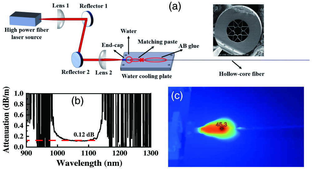
The schematic of the power transmission system is shown in Fig. 1(a). The fiber laser source emits a CW laser with the maximum output power of 1500 W at the wavelength of 1070 nm. The output fiber is a 20 µm core solid fiber fabricated with an end-cap, and the beam quality
![]()
Figure 1.(a) Experiment setup of the power transmission system. Inset: cross-section electronic micrograph of HCF. (b) Transmission loss of HCF used at 1 µm wavelength band; (c) thermal image of the input end.
The input end of the HCF is fabricated with an end-cap for fixing and protection of the HCF. The end-cap is custom made by a company from China. The HCF with the end-cap is fixed on the water cooling plate designed by us. An approximately 25-cm-long HCF is water cooled, which contains 10 cm without coating and 15 cm with coating, and the red cross sign in Fig. 1(a) is the junction between the cladding and the coating. The cladding part is applied with matching paste to filter the cladding light, a small distance of HCF splicing with an end-cap is suspended, and water is used to realize cooling. The front of the coating part is applied with AB glue for a better cooling effect. At the transmission power of 1 kW, apart from the cladding part applied with matching paste, as shown in Fig. 1(c), the temperature is 45.3°C, and the whole 1-m-long HCF has no obvious temperature rise.
The HCF end-cap is fabricated with a large diameter splicing system. Due to the special hollow-core structure of the HCF, the shape of the core changes when heated, as shown in Fig. 2(a), where the negative curvature of the core is destroyed, and the ice-cream capillaries are changed to triangles. Either the core diameter or the mode field diameter becomes larger. To avoid excessive deformation, the heating temperature is controlled strictly. The core of the HCF is filled with air, and, after splicing with HCF, there is a surface between the silica and the air, which causes Fresnel reflection. The testing system in Fig. 2(b) is used to measure the Fresnel reflection.
![]()
Figure 2.(a) Cross-section micrograph of HCF after splicing with end-cap; (b) schematic of test for Fresnel reflection.
3. Results
The power transmission results for the kW-level power coupling experiment are shown in Fig. 3. The left axis shows the transmission efficiency, which is the transmission power after the HCF divides the power of the laser source, and the right axis shows the transmission power. The highest transmission power is 1021 W, as the laser source power is 1167 W, and the total transmission efficiency is as high as 87.5%. Coupling efficiency has a fluctuation under the input power of 300 W, which is because the power meter has a big fluctuation at a relatively low power level, and the efficiency is uncertain. When the input power is above 300 W, the transmission efficiency is stable at around 87.5% when the power of the laser source is increased. Considering the loss of the lenses and the reflectors of around 0.03 dB, the Fresnel reflection of the HCF end-cap of around 0.15 dB, and the fiber loss of around 0.12 dB, the estimated coupling efficiency is about 94%. The coupling efficiency of 94% indicates that this is an efficient coupling method. Because the ratio of focal lengths of two lenses we used is one, the mode field diameter of the beam injected into the hollow core should be the same as the mode field of the output fiber of the laser source. But, in practice, power monitoring at the output end is used, the focal lengths are changed to ensure the highest coupling efficiency, and the real mode field diameter of the beam after lenses is very close to that of the HCF, so the coupling efficiency is as high as 94%. The other 6% loss may be the mismatch of the mode field shape, and some light transmits in the cladding region with higher loss.
![]()
Figure 3.Measured transmission power and transmission efficiency versus input power.
The power stability is measured, and the results are shown in Fig. 4. The power of the laser source has a fluctuation up and down because of the periodic working of the water cooling, and the change of the fiber temperature will influence the output power. For the purpose of protecting the system, we do not measure the power stability at the maximum transmission power. As the transmission power is 950 W, during the testing time of 60 min, the transmission power is declined from 950 W to 930 W, which is due to heat accumulation; as the temperature of the HCF changed, there was a micro deformation for the HCF, which caused the decline of the efficiency. It is possible because, as the heat accumulated, the front end of the HCF has a higher temperature of around 45.3°C, the rear fiber has a lower temperature under the action of thermal expansion and cold contraction, and the input end of the HCF may have a minor change causing the overlap between the high power and the capillaries. Therefore, the output power decreased. But, because of the fixture of the end-cap, the change occurs slowly. As the transmission power dips to 915 W, the power changes periodically with the power of the laser source, and the power fluctuation is less than
![]()
Figure 4.Power stability of the laser source and the transmission power of 915 W and 950 W.
Beam quality factor
![]()
Figure 5.(a) Beam quality M2 versus transmission power; (b) beam quality M2 versus time when the transmission power is 900 W. Inset: beam profiles of waist.
4. Conclusions
In conclusion, through splicing the HCF with the end-cap, a high-efficiency and stable coupling method for HCF is achieved. The maximum transmission power reaches 1021 W, as the input power is 1167 W with a high efficiency of 87.5 %. Besides, the system can keep good power stability and beam quality at the power level of 900 W. The HCF does not have obvious heat positions apart from the exposed cladding applied with matching paste. By further optimizing the system, improving the coupling efficiency, and improving the heat treatment technology, the HCF has the potential to transmit higher power, which is significant for the development of high-power FGLs.
References
[1] P. Russell, P. Hölzer, W. Chang, A. Abdolvand, J. C. Travers. Hollow-core photonic crystal fibres for gas-based nonlinear optics. Nat. Photonics, 8, 278(2014).
[2] A. V. V. Nampoothiri, A. M. Jones, C. Fourcade-Dutin, C. Mao, N. Dadashzadeh, B. Baumgart, Y. Wang, M. Alharbi, T. Bradley, N. Campbell. Hollow-core optical fiber gas lasers (HOFGLAS): a review [Invited]. Opt. Mater. Express, 2, 948(2012).
[3] H. Li, W. Huang, Y. Cui, Z. Zhou, Z. Wang. 3 W tunable 1.65 m fiber gas Raman laser in D2-filled hollow-core photonic crystal fibers. Opt. Laser Technol., 132, 106474(2020).
[4] M. S. Astapovich, A. V. Gladyshev, M. M. Khudyakov, A. F. Kosolapov, M. E. Likhachev, I. A. Bufetov. Watt-level nanosecond 4.42-µm Raman laser based on silica fiber. IEEE Photonics Technol. Lett., 31, 78(2019).
[5] L. Cao, S. Gao, Z. Peng, X. Wang, P. Wang. High peak power 2.8 µm Raman laser in a methane-filled negative-curvature fiber. Opt. Express, 26, 5609(2018).
[6] A. V. Gladyshev, A. F. Kosolapov, M. M. Khudyakov, Y. Yatsenko, A. N. Kolyadin, A. A. Krylov, A. Pryamikov, A. S. Biriukov, M. E. Likhachev, I. A. Bufetov. 2.9, 3.3 and 3.5 µm Raman lasers based on revolver hollow-core silica fiber filled by H2 /D2 gas mixture. IEEE J. Sel. Top. Quantum Electron., 24, 0903008(2018).
[7] F. C. Ouny, B. J. Mangan, A. V. Sokolov, F. Benabid. High power 55 watts CW Raman fiber-gas-laser. Conference on Lasers and Electro-Optics (CLEO), CTuM3(2010).
[8] F. Benabid. Stimulated Raman scattering in hydrogen-filled hollow-core photonic crystal fiber. Science, 298, 399(2002).
[9] F. B. A. Aghbolagh, V. Nampoothiri, B. Debord, F. Gerome, L. Vincetti, F. Benabid, W. Rudolph. Mid IR hollow core fiber gas laser emitting at 4.6 um. Opt. Lett., 44, 383(2019).
[10] Y. Cui, W. Huang, Z. Wang, M. Wang, Z. Zhou, Z. Li, S. Gao, Y. Wang, P. Wang. 4.3 µm fiber laser in CO2 fibers. Optica, 6, 951(2019).
[11] Z. Zhou, N. Tang, Z. Li, W. Huang, Z. Wang, W. Wu, W. Hua. High-power tunable mid-infrared fiber gas laser source by acetylene-filled hollow-core fibers. Opt. Express, 26, 19144(2018).
[12] M. Xu, Y. Fei, K. Jonathan. Mid-infrared 1 W hollow-core fiber gas laser source. Opt. Lett., 42, 4055(2017).
[13] M. R. A. Hassan, F. Yu, W. J. Wadsworth, J. C. Knight. Cavity-based mid-IR fiber gas laser pumped by a diode laser. Optica, 3, 218(2016).
[14] A. M. Jones, A. V. V. Nampoothiri, A. Ratanavis, T. Fiedler, W. Rudolph. Mid-infrared gas filled photonic crystal fiber laser based on population inversion. Opt. Express, 19, 2309(2011).
[15] X. Zhu, D. Wu, Y. Wang, F. Yu, Q. Li, Y. Qi, J. Knight, S. Chen, L. Hu. Delivery of CW laser power up to 300 watts at 1080 nm by an uncooled low-loss anti-resonant hollow-core fiber. Opt. Express, 29, 1492(2021).
[16] S. H. Drich, J. Rothhardt, S. Demmler, M. Tschernajew, A. Hoffmann, M. Krebs, A. Liem, O. D. Vries, M. Pl Tner, S. Fabian. Scalability of components for kW-level average power few-cycle lasers. Appl. Opt., 55, 1636(2016).
[17] F. Benabid, F. Couny, J. Knight, T. Birks, P. Russell. Compact, stable and efficient all-fibre gas cells using hollow-core photonic crystal fibres. Nature, 434, 488(2005).
[18] P. S. Light, F. Couny, F. Benabid. Low optical insertion-loss and vacuum-pressure all-fiber acetylene cell based on hollow-core photonic crystal fiber. Opt. Lett., 31, 2538(2006).
[19] K. Z. Aghaie, M. J. F. Digonnet, S. Fan. Optimization of the splice loss between photonic-bandgap fibers and conventional single-mode fibers. Opt. Lett., 35, 1938(2010).
[20] S. Gao, Y. Wang, C. Tian, P. Wang. Splice loss optimization of a photonic bandgap fiber via a high V-number fiber. IEEE Photonics Technol. Lett., 26, 2134(2014).
[21] H. Li, W. Huang, W. Pei, Z. Zhou, Y. Cui, M. Wang, Z. Wang. All-fiber gas Raman laser oscillator. Opt. Lett., 46, 5208(2021).
[22] W. Pei, H. Li, W. Huang, M. Wang, Z. Wang. Hydrogen molecules rotational stimulated Raman scattering in all-fiber cavity based on hollow-core photonic crystal fibers. Crystals, 11, 711(2021).
[23] W. Pei, H. Li, W. Huang, M. Wang, Z. Wang. All-fiber tunable pulsed 1.7 µm fiber lasers based on stimulated Raman scattering of hydrogen molecules in hollow-core fibers. Molecules, 26, 4561(2021).
[24] W. Pei, H. Li, W. Huang, M. Wang, Z. Wang. Pulsed fiber laser oscillator at 1.7 µm by stimulated Raman scattering in H2-filled hollow-core photonic crystal fibers. Opt. Express, 29, 33915(2021).
[25] W. Pei, H. Li, W. Huang, M. Wang, Z. Wang. All-fiber gas Raman laser by D2-filled hollow-core photonic crystal fibers. Photonics, 8, 382(2021).
[26] X. Zheng, B. Debord, L. Vincetti, B. Beaudou, F. A. Benabid. Fusion splice between tapered inhibited coupling hypocycloid-core Kagome fiber and SMF. Opt. Express, 24, 14642(2016).
[27] R. Zeltner, S. Xie, R. Pennetta, P. Russell. Broadband, lensless and optomechanically stabilised coupling into microfluidic hollow-core photonic crystal fiber using glass nanospike. ACS Photonics, 4, 378(2016).
[28] W. Huang, Y. Cui, Z. Zhou, Z. Li, Y. Chen, Z. Wang. Towards all-fiber structure pulsed mid-infrared laser by gas-filled hollow-core fibers. Chin. Opt. Lett., 17, 091402(2019).
[29] Y. Cui, Z. Zhou, W. Huang, Z. Li, Z. Wang. Quasi-all-fiber structure CW mid-infrared laser emission from gas-filled hollow-core silica fibers. Opt. Laser Technol., 121, 105794(2019).
[30] W. Huang, Y. Cui, X. Li, Z. Zhou, Z. Wang. Low-loss coupling from single-mode solid-core fibers to anti-resonant hollow-core fibers by fiber tapering technique. Opt. Express, 27, 37111(2019).
[31] R. Yu, C. Wang, F. Benabid, K. S. Chiang, L. Xiao. Robust mode matching between structurally dissimilar optical fiber waveguides. ACS Photonics, 8, 857(2021).
[32] C. Wang, R. Yu, B. Debord, F. Gérôme, F. Benabid, K. S. Chiang, L. Xiao. Ultralow-loss fusion splicing between negative curvature hollow-core fibers and conventional SMFs with a reverse-tapering method. Opt. Express, 29, 22470(2021).
[33] J. Shi, X. Ye, Y. Cui, W. Huang, H. Li, Z. Zhou, M. Wang, Z. Chen, Z. Wang. All-fiber gas cavity based on anti-resonant hollow-core fibers fabricated by splicing with end caps. Photonics, 8, 371(2021).


Set citation alerts for the article
Please enter your email address

© Copyright 2018-2021 | Chinese Laser Press. All Rights Reserved 沪ICP备15018463号-20