
B. Martinez, S. N. Chen, S. Bolaños, N. Blanchot, G. Boutoux, W. Cayzac, C. Courtois, X. Davoine, A. Duval, V. Horny, I. Lantuejoul, L. Le Deroff, P. E. Masson-Laborde, G. Sary, B. Vauzour, R. Smets, L. Gremillet, J. Fuchs. Numerical investigation of spallation neutrons generated from petawatt-scale laser-driven proton beams[J]. Matter and Radiation at Extremes, 2022, 7(2): 024401
- Matter and Radiation at Extremes
- Vol. 7, Issue 2, 024401 (2022)
Abstract
I. INTRODUCTION
Neutron beams are commonly employed in scientific research, medicine, and industry for a wide range of applications.1 In practice, they are generated from nuclear reactions initiated by accelerator proton beams. Conventional neutron source facilities range from compact tubes to large-scale linacs like the Spallation Neutron Source (Oak Ridge, USA)2 and the European Spallation Source (Lund, Sweden)3 currently under construction, where 1–2 GeV protons hit a heavy-metal target to produce neutrons through spallation reactions. These consist of a cascade of binary collisions between the incident projectile and the nucleons inside the target nuclei, followed by de-excitation (or evaporation) of the excited nuclei, leading to the emission of neutrons, and also, to a smaller extent, protons, alpha particles, lighter heavy ions, gamma rays, etc.4
The production of bright neutron beams using high-power short-pulse lasers was demonstrated in the early 2000s (see Ref. 5 and references therein for an overview) and has since been actively investigated. Laser-generated neutrons have already been utilized for a variety of purposes, such as materials testing for fusion experiments,6 nondestructive imaging,7 and studies of equations of state via neutron resonance spectroscopy.8,9 Such neutron sources exploit laser-driven energetic protons10 (with current record high energies of ∼100 MeV),11,12 electrons,13 or gamma-ray photons14 as the primary drivers, with typical cross sections in the barn range.5,15 Most previous studies on this topic have been focused on improving the yield10,14 or the energy spectrum16 of the emitted neutrons.
Progress in high-brightness neutron sources is a necessary step toward the laboratory production of neutron-rich isotopes via rapid neutron captures (r-process), which would allow nuclear physics models to be tested17 and improve our understanding of the formation of heavy nuclei in the Universe.18,19 Half of the elements heavier than iron (Z = 26), and all those beyond bismuth (Z = 83), are indeed believed to originate from the r-process during cataclysmic astrophysical events such as supernova explosions or neutron star mergers.20 To compensate for the short lifespan (in the millisecond range) of the intermediate isotopes, a minimum neutron flux >1020 n cm−2 s−1 is estimated to be necessary for the r-process to operate.21 This value is several orders of magnitude above the capability of conventional accelerator-based facilities (∼1016 n cm−2 s−1),22 but also significantly larger than the current record high flux (∼1018 n cm−2 s−1) obtained with intense short-pulse lasers.10,14 Neutron fluxes as high as ∼1024 n cm−2 s−1 can be attained at large-scale laser fusion facilities,23 but with limited user access and very few shots per experiment. Systematic laboratory investigations of r-process nucleosynthesis therefore require further development of laser-based neutron sources.
Laser acceleration of proton beams should greatly benefit from next-generation petawatt or multi-petawatt facilities, delivering pulse intensities in excess of 1021 W cm−2.24–31 At such intensities, the dominant ion acceleration mechanism is expected to transition from target normal sheath acceleration (TNSA)32 to radiative pressure acceleration (RPA) or light-sail acceleration (LSA).33 The accompanying increase in proton energy above the 100 MeV level should trigger spallation reactions in a secondary neutron-producing target, entailing the emission of multiple neutrons per incident proton (see Fig. 1).
![]()
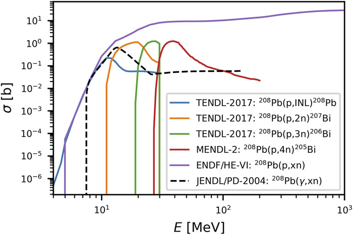
Figure 1.Energy-differential cross sections of proton-induced nuclear reactions releasing different numbers of neutrons (solid curves) and of total neutron production by photonuclear reactions (black dashed curve) in Pb, as given by the ENDF/B-VIII database.
In Fig. 1, the cross sections of various neutron-producing reactions (as given by the ENDF/B-VIII database34) are plotted as a function of the projectile (proton or photon) energy (solid lines). Already at relatively low proton energies of tens of MeV, easily produced by current high-intensity laser facilities, neutrons are efficiently produced. It is therefore clear that to access reactions with increased neutron multiplicity, higher projectile energies are needed.
In the present study, we will focus on exploiting protons as a driver to induce the desired neutron beam. This is justified, because the cross sections of photonuclear reactions in Pb (black dashed curve in Fig. 1), although comparable to those of proton-induced reactions around 10 MeV, are 100 times lower at higher energy. Thus, integrating the expected production of neutrons, induced by either photons or protons, in the cases that will be addressed at the LMJ-PETAL35 and Apollon36 laser facilities shows that the neutron yield induced by protons is at least ten times higher than that due to photons. The characteristics of the proton beams considered here will be detailed below, while to estimate the photons that can be generated by PETAL and by Apollon, we refer respectively to Ref. 37 and to Refs. 38 and 39. Hence, photonuclear reactions will be neglected in a first-order approach in the physical situations treated in the following. Yet, these could prove to be influential at more extreme laser intensities (≥1023 W cm−2, not presently achievable) for which massive high-energy synchrotron radiation is expected to arise.40
This paper reports on a numerical study aiming to characterize the neutron yield and flux achievable at the petawatt-class LMJ-PETAL and Apollon laser facilities. Our results are also relevant to similar laser systems, such as ELI Beamlines41 and ELI-NP.42 Overall, this is done by combining particle-in-cell (PIC) simulations of the laser-driven particle acceleration in a thin-foil target with Monte Carlo calculations of the proton-induced nuclear reactions in a secondary target. In Sec. II, we first investigate numerically how the production of spallation neutrons varies with the target material and incident proton energy. In Sec. III, we present the results of PIC simulations of laser-based proton acceleration from solid foils under conditions accessible at LMJ-PETAL and Apollon. The generation of spallation neutrons from a Pb convertor by the PIC-predicted proton beams is studied in Sec. IV via Monte Carlo simulations, which predict that neutron yields of 108–1011 n sr−1 and neutron fluxes of 1023–1024 n cm−2 s−1 are achievable. Finally, our results are summarized and discussed in Sec. V.
II. DEPENDENCE OF NEUTRON PRODUCTION ON TARGET MATERIAL AND PROTON ENERGY
We start by briefly examining the neutron yield from spallation as a function of the converter target material and the projectile proton energy in a range within the reach of present or near-future laser systems.11,12,33 For this purpose, we used the FLUKA 3D Monte Carlo code43,44 to simulate the nuclear reactions induced during irradiation of a convertor target by a monokinetic and monodirectional proton beam. The proton beam energy was varied from ϵp = 25 MeV to 1 GeV. Four target materials were considered: aluminum (Z = 13), copper (Z = 29), silver (Z = 47), and lead (Z = 82), a standard material for spallation purposes.
The simulated target was a 50-cm-radius cylinder of variable length L. Introducing λ, the energy-dependent projected range of a proton due to ionization and excitation,45 five L/λ values (0.2, 0.4, 0.6, 0.8, 1) were considered for each material and input proton energy. The values of λ corresponding to our parameter range are given in Table I.
| Proton energy (MeV) | Al | Cu | Ag | Pb |
|---|---|---|---|---|
| 25 | 0.315 | 0.117 | 0.115 | 0.135 |
| 50 | 1.08 | 0.391 | 0.380 | 0.435 |
| 100 | 3.70 | 1.31 | 1.26 | 1.43 |
| 250 | 17.9 | 6.28 | 5.97 | 6.64 |
| 500 | 55.0 | 19.1 | 18.1 | 19.9 |
| 1000 | 152 | 52.9 | 49.7 | 54.2 |
Table 1. Projected range λ (cm) for protons in various materials and for various energies.
Figure 2 shows the L/λ dependence of the neutron multiplicity Mn, i.e., the number of neutrons produced per incident proton as a function of its input energy ϵp, for the different materials under consideration. Collisional stopping and scattering of the projectiles and product neutrons are taken into account in these simulations. The main result is that, whatever the material, Mn rises sharply (i.e., approximately quadratically) with ϵp when L/λ is kept constant. In Ag and Pb, Mn approaches unity (a usual criterion for the onset of spallation) for ϵp ≃ 250 MeV and L/λ ≲ 1. At higher ϵp, Mn ≥ 1 can be achieved in lower L/λ targets. The maximum neutron multiplicity (Mn ∼ 10) is obtained in Pb with ϵp = 1 GeV and L/λ = 0.4–0.6. It should be noted that the increasing trend of Mn with ϵp ceases beyond ϵp ≃ 0.5–1 GeV when L/λ ≳ 0.5. This is a known behavior in spallation studies, ascribed to the increasingly significant contribution of pion production to proton energy losses.4
![]()
Figure 2.Number of neutrons emitted per incident proton as a function of the target material and incident proton energy, as simulated by FLUKA.
At fixed proton energy, Mn is predicted to rise by a relatively modest (∼3×) factor when the normalized target thickness is increased from L/λ = 0.2 to 1. Finally, at fixed ϵp ≤ 0.5 GeV and L/λ, Mn shows a moderate increase with atomic number, namely, a ∼3× enhancement between Al and Pb. At ϵp = 1 GeV, however, a ∼10× enhancement is obtained.
III. PIC SIMULATIONS OF LASER ACCELERATION OF PROTONS
We now numerically characterize the neutron beams that could be produced through spallation reactions in the near future using the LMJ-PETAL and Apollon laser systems. Our methodology comprises two steps. First, we have employed the CALDER code46 to perform multidimensional PIC simulations of proton acceleration from laser-irradiated foil targets, under conditions relevant to the LMJ-PETAL and Apollon lasers, as detailed in Table II. Second, the proton distributions recorded in the PIC simulations have been used as input in 3D FLUKA Monte Carlo simulations,44 describing the proton transport and associated nuclear reactions through a secondary Pb convertor target. This procedure is sketched in Fig. 3. In this section, we present the results of the proton acceleration simulations for the LMJ-PETAL and Apollon cases.
| Laser | Wavelength (μm) | Pulse duration (fs) | Pulse energy (J) | Pulse intensity (W/cm2) | Target size and composition | Simulation mesh size (nm) |
|---|---|---|---|---|---|---|
| 0.5 PW LMJ-PETAL | 1 | 610 | 320 | 8 × 10¹⁸ | 5 μm CH and Al | 32 |
| 0.6 PW Apollon | 0.8 | 20 | 12 | 2 × 10²¹ | 64 nm CH | 3.2 |
| 6 PW Apollon | 0.8 | 20 | 120 | 192 nm CH | 3.2 |
Table 2. Parameters of the 2D CALDER PIC simulations performed for each considered laser system.
![]()
Figure 3.Conceptual setup of the numerical study.
A. Proton acceleration at the 0.5 PW LMJ-PETAL laser facility
Proton acceleration using LMJ-PETAL was investigated in a quasi-3D geometry with the CALDER-CIRC PIC code.47 In this code, the particles are advanced in 3D Cartesian space, but the fields and particle densities are computed in cylindrical coordinates (x, r, θ), using a reduced number of Fourier angular modes (only two angular modes were used here). This technique allows one to describe both the axisymmetric self-generated plasma fields (such as the TNSA field) and the non-axisymmetric (linearly polarized) laser fields at a much lower computational cost than in a fully 3D simulation. Based on experimental measurements,48 the PETAL laser beam was modeled as the sum of two superimposed, time-synchronized Gaussian laser waves, each of 610 fs FWHM duration, polarized along the y axis and propagating along the x axis. This was done in order to best describe the measured complex focal spot of PETAL, which is composed of a central, intense, spot, surrounded by low-intensity extended wings (see Fig. 1 in Ref. 48). The central component of the laser spot was modeled by a Gaussian having a FWHM width of 20 μm and a dimensionless field strength aL = e EL/me cωL = 1.1. The wings were modeled by a Gaussian with a 130 μm FWHM width and a dimensionless field strength aL = 1.3. The cumulative maximum laser intensity was of 8 × 10¹⁸ W cm−2.48
The target consisted of a semitransparent Al preplasma and an overcritical plastic (CH) plasma (5 μm thick). Henceforth,
With the above parameters, proton acceleration proceeds according to the standard TNSA mechanism.32,33 During the interaction, the laser wave propagates through the extended undercritical preplasma while driving the electrons to relativistic energies through various processes. These have been examined in detail by some of the present authors in a recent study,48 which revealed the importance of stochastic electron heating as a result of stimulated laser backscatter and laser filamentation in the preplasma.
After traversing the target, the laser-generated hot electrons form a negatively charged cloud at the backside. The associated electrostatic field then accelerates the plasma ions in the +x direction. Figure 4 displays the longitudinal phase space of the protons as measured at t = 3.4 ps. The proton distribution exhibits a linear shape typical of TNSA, extending over ∼100 μm longitudinally and (from analysis of the x − r proton density map) ∼300 μm transversely. The corresponding energy spectrum of the protons is plotted in Fig. 5. It has a decreasing exponential shape characteristic of TNSA, with a cutoff energy of ∼37 MeV.
![]()
Figure 4.Longitudinal (
![]()
Figure 5.Proton energy spectrum from the CALDER-CIRC simulation using the LMJ-PETAL laser parameters (blue curve). An experimental proton spectrum obtained at LMJ-PETAL (see the text for details) is plotted as orange dots.
To confirm the validity of our approach, we compare in Fig. 5 the proton distribution predicted by CALDER-CIRC with an experimental one, which was recorded by us at LMJ-PETAL. It was measured with the CRACC diagnostic, which uses a radiochromic film (RCF) stack as detector; the spectrum is shown here after angular integration over the whole surface of the films.50 In this shot, the PETAL laser irradiated a 7 μm-thick titanium foil with a pulse of 960 fs duration, 354 J energy, and ∼5.3 × 10¹⁸ W cm−2 intensity, i.e., parameters relatively close to those of the simulation. Although the experimental proton spectrum is characterized by a harder slope and a larger cutoff energy (∼42 MeV) than the simulated spectrum, the two curves agree fairly well with each other. This result is particularly satisfactory, given the above simplifications made to the simulation in order to handle the spatiotemporal scales of the experiment. It should be noted that the experimental cutoff energy represents the last recorded point on the RCF stack, although there were more RCFs in the stack; such sharp cutoffs are common features of TNSA-accelerated proton beams.
B. Proton acceleration at the 0.6–6 PW Apollon laser facility
Proton acceleration using Apollon was simulated in a 2D Cartesian geometry with the CALDER PIC code. The Apollon pulse was modeled as a 0.8 μm wavelength Gaussian electromagnetic wave linearly polarized along the (in-plane) y axis, with 20 fs FWHM duration and 5 μm FWHM transverse size. We considered two operating regimes of the Apollon laser, characterized by a peak intensity of 2 × 10²¹ W cm−2 (0.6 PW regime) and 2 × 10²² W cm−2 (6 PW regime), respectively; see Table II. Note that the temporal profile of the laser pulse is truncated at twice its FHWM duration ahead of the peak, i.e., the laser is switched on at that time. This starting point is chosen since it corresponds to an intensity that is 10−5 times the peak value. This ratio is close to what can be achieved using plasma mirrors as ultrafast switches, allowing one to virtually eliminate any ionizing light in the laser pulse prior to that level.51 In practice, however, modulations in the pulse spectrum36 could lead to the laser temporal profile deviating from the perfect Gaussian shape that we assume here. This may induce premature expansion of the target surface, thereby affecting the irradiation conditions at the pulse maximum and thus the overall performance of the target. This will have to be taken in consideration, using experimental data for the laser temporal profile, when carefully planning experimental campaigns at maximum power.
The target was a thin, solid-density CH foil with sharp gradients. It was assumed to be fully ionized (yielding an electron density ne = 200nc) and initialized at a temperature of 100 eV. Its thickness, l, was chosen based on the parametric simulation study of Ref. 29. The optimum foil thickness for RPA by femtosecond laser pulses was found to be lopt ≃ 0.5aL(nc/ne)λL. In the 0.6 PW (respectively, 6 PW) regime, corresponding to aL = 30 (respectively, aL = 96), we chose l = 64 nm (respectively, l = 192 nm), close to lopt = 60 nm (respectively, l = 192 nm). Each of the plasma constituents (C6+, H+, electrons) was modeled by 100 macroparticles per cell. The laser pulse interacted at normal incidence with the target. Absorbing boundary conditions were adopted for the fields and particles. The simulation domain was set to Lx × Ly = 40 × 50 μm2 at 0.6 PW (56 × 96 μm2 at 6 PW), with a spatial resolution Δx = Δy = 3.2 nm.
The proton acceleration dynamics is illustrated by the longitudinal proton phase spaces shown at two successive times in Figs. 6 and 7 for the 0.6 and 6 PW irradiation cases, respectively. In each panel is also plotted (in blue) a lineout (along the laser axis) of the accelerating longitudinal electric field 〈Ex〉 (where 〈·〉 indicates averaging over the laser cycle). This field is scaled (in units of E0 = 3.2 × 10¹² V m−1) to fit within the px axis of the phase space.
![]()
Figure 6.Proton acceleration using the 0.6 PW Apollon laser parameters:
![]()
Figure 7.Proton acceleration using the 6 PW Apollon laser parameters:
At time t = −20 fs (here the time origin t = 0 is when the laser maximum reaches the target) in Figs. 6(a) and 7(a), proton acceleration originates from both RPA and TNSA,12,33 as demonstrated by the two 〈Ex〉 peaks at the front and rear sides of the target. At the front side, the electrons are pushed and compressed by the laser’s ponderomotive force. The ensuing charge separation generates an electrostatic field 〈Ex〉 ≃ 2E0 at 0.6 PW (≃10E0 at 6 PW), which in turn accelerates the front-side protons in the forward direction. These RPA protons have then reached a longitudinal momentum px/mic ≃ 0.015 (≃0.06 at 6 PW). Simultaneously, the backside protons have started expanding toward vacuum owing to TNSA triggered by the fast electrons. The associated (on-axis) electric field 〈Ex〉 ≃ 1.5E0 (≃3E0 at 6 PW), however, turns out to be weaker than the one induced by the radiation pressure (especially at 6 PW). At this early stage of the interaction, the maximum momentum of the TNSA protons is of px/mic ≃ 0.0011 (≃0.02 at 6 PW).
At t = +4 fs [Figs. 6(b) and 7(b)], the RPA protons have caught up with the TNSA protons, and the two previously observed field structures have merged into a single accelerating structure. Importantly, the expanding, lower-density plasma has then become transparent to the central part of the laser pulse. This causes the electrons to be further heated and the accelerator field strength to be boosted to 〈Ex〉 ≃ 7.5E0 at 0.6 PW and 〈Ex〉 ≃ 25E0 at 6 PW, which, in both cases, represents about a quarter of the laser field amplitude.
As a result of this sequence of processes, the protons eventually attain high cutoff energies (≃115 MeV at 0.6 PW and ≃660 MeV at 6 PW) as demonstrated by the energy spectra displayed in Fig. 8. Note that these spectra are recorded when the protons reach the right-hand side of the box: their spatial distribution then has a ∼20–30 μm transverse size, comparable to the distance traveled. The electrostatic field seen by the fastest protons should therefore be relatively well captured by our 2D simulation. We acknowledge, however, that the combination of a 2D geometry and laser polarized along the (in-plane) y-axis, likely leads to a significant overestimation of the electron heating, and hence of the accelerator field compared with a real-world 3D configuration.52 This, on top of the idealized temporal laser profile and target conditions (i.e., the neglect of preplasma formation) that we considered, is bound to degrade the performance in the experiments compared with our simulation results.
![]()
Figure 8.PIC-simulated proton spectra using (a) the 0.6 PW and (b) the 6 PW Apollon laser parameters. In (a), the integrated number of protons above 10 MeV is ∼1011, corresponding to a laser-to-proton energy conversion efficiency of ∼5%. In (b), there are 5 × 10¹¹ protons above 20 MeV, corresponding to a ∼12% conversion efficiency.
IV. MONTE CARLO SIMULATIONS OF NEUTRON GENERATION
In the CALDER simulations, the properties (statistical weight, position, momentum, and time of arrival) of the macro-protons crossing a virtual detector plane near the right-hand side of the simulation box were all recorded. The resulting output files contained between about 105 (PETAL) and 107 (Apollon) macro-protons. The proton distributions obtained from the 2D Apollon simulations had to be post-processed in order to be used as input in the FLUKA 3D Monte Carlo code. For this purpose, they were converted into cylindrically symmetric distributions. Specifically, the position and momentum of each macro-proton were rotated around the x axis by a random azimuthal angle. Moreover, the transverse density profile of the proton distribution was interpreted as a radial density profile: the statistical weight of each macro-proton (a linear density in a 2D simulation) was therefore multiplied by its transverse radius to obtain a dimensionless quantity, corresponding to the number of physical protons represented by the macro-proton. These numbers are reflected in the spectra shown in Fig. 8 and are further detailed below.
The convertor target was taken to be a lead cylinder of fixed radius 5 cm and varying length (10 μm ≤ l ≤ 10 cm), located 0.5 cm behind the proton-generating target. To get good statistics on the simulated events, we carried out 1000 independent Monte Carlo simulations for each set of initial conditions. Only those neutrons crossing the target rear side were characterized.
The energy-angle spectra of the outgoing neutrons from a 0.3-mm-thick converter Pb target as predicted by FLUKA are shown for the LMJ-PETAL case in Fig. 9(a) and the 0.6–6 PW Apollon cases in Figs. 9(b) and 9(c). Overall, the neutron energy spectra show an exponentially decreasing shape up to a maximum energy close to that of the incident protons. This is more clearly seen in Fig. 12(b), obtained from angular integration of the spectra of Fig. 9. It is worth noting that the lower-energy part of the neutron distribution is essentially isotropic, while its higher-energy part is preferentially emitted in the initial direction of the proton beam.
![]()
Figure 9.Energy-angle spectrum of the neutrons escaping from a 0.3-mm-thick Pb converter target for (a) LMJ-PETAL, (b) 0.6 PW Apollon, and (c) 6 PW Apollon laser parameters.
Figure 10 plots, as a function of the Pb target length l, the fraction of kinetic energy lost by the primary protons through nuclear reactions (blue curves) and that transmitted through the target (green curves). In the PETAL case, the proton beam energy is wholly dissipated for l ≥ 0.1 cm. In the 0.6 PW Apollon case, this takes place for l ≥ 1 cm, while in the 6 PW case, the absorption is limited to ∼80% at l = 10 cm.
![]()
Figure 10.Energy fraction of the incident protons dissipated by nuclear reactions (blue) and transmitted through the target (green) as a function of the thickness
Figure 11(a) shows how the total number (per unit solid angle) of outgoing neutrons varies with l. Under the LMJ-PETAL conditions, the neutron number is seen to rise with l up to l ≃ 0.1 cm and to saturate at a ∼108 n level in the range 0.1 cm ≤ l ≤ 3 cm, before dropping at larger l as a result of reabsorption. In the 0.6 and 6 PW Apollon cases, owing to higher proton energies, saturation occurs in thicker targets, namely, at ∼5 × 10⁸ n for 1 ≤ l ≤ 3 cm and at ∼1011 n for 3 ≤ l ≤ 10 cm, respectively (the plateau observed at 6 PW may actually extend beyond the range of thicknesses considered here). These trends are consistent with the evolution of the dissipated proton energy as discussed above. Interestingly, the neutron yield is predicted to be quite similar for the LMJ-PETAL and 0.6 PW Apollon lasers. At first glance, this result may seem surprising, given that LMJ-PETAL generates about 50 times more fast protons than 0.6 PW Apollon (∼5 × 10¹² in a 2–40 MeV energy range vs ∼1011 in a 10–120 MeV range), owing to its relatively large spot size and long pulse duration. Yet the lower yield of protons achieved at 0.6 PW Apollon is compensated for by their higher cutoff energy, which increases their neutron generation efficiency. Such an enhancement is even more dramatic using the 6 PW Apollon parameters, in which case a sharp rise in the proton energies is observed. The ∼5 × 10¹¹ protons then produced above 20 MeV are predicted to translate into a two orders of magnitude higher neutron yield.
![]()
Figure 11.(a) Number (normalized to unit solid angle) and (b) maximum flux of the neutrons crossing the rear side of the Pb converter target, as a function of its thickness l. The incident proton beam is that predicted by PIC simulations in the LMJ-PETAL and 0.6–6 PW Apollon cases, as labeled.
Figure 11(b) plots the corresponding variations in the maximum neutron flux at the backside of the Pb target. Note that FLUKA takes account of the time of injection of each proton into the convertor, so that the temporal profile of the total neutron flux across a given surface can be computed. The maximum flux appears to be reached in l ≲ 100 μm targets and to drop in increasingly thick targets. Values in excess of ∼1 × 10²³ n cm−2 s−1 are expected at LMJ-PETAL and 0.6 PW Apollon, while a maximum flux as high as ∼4 × 1024 n cm−2 s−1 is found with the 6 PW Apollon parameters. This trend results from the increase in duration and transverse size of the neutron distribution when the converter target is made thicker. These variations originate from the energy dispersion of the incident proton beam (which leads to an elongation of the proton beam, and therefore of the generated neutron beam) as well as from elastic scatterings of both the protons and neutrons throughout the target (which mainly account for the transverse size of the neutron source). The temporal dependence of the neutron flux is illustrated in Fig. 12(a) for LMJ-PETAL. It is observed that upon thickening the target from l = 10 μm to 1 cm, the neutron pulse is lengthened from ∼3 ps to ∼6 ns. The correlation between the neutron source duration and transverse size is clearly shown in Fig. 13. The three laser configurations give rise to similar behavior: very compact neutron sources, of a few picoseconds duration and ∼50–100 μm width only, are expected from l ≤ 100 μm Pb targets, which evolve into sources a few nanoseconds long and a centimeter wide when centimeter-thick Pb targets are employed.
![]()
Figure 12.(a) Time-dependent neutron flux across the Pb converter backside for the LMJ-PETAL parameters. (b) Neutron energy spectra from a
![]()
Figure 13.Transverse size vs duration of the simulated neutron beam in the LMJ-PETAL, 0.6 PW Apollon, and 6 PW Apollon cases, and for various thicknesses, as indicated.
V. DISCUSSION AND SUMMARY OF THE PROPERTIES OF SIMULATED NEUTRON SOURCES
We have assessed here the possibility of exploiting spallation reactions to generate high-flux neutron sources using petawatt-class lasers as the primary drivers. We have tested this scenario by combining two simulation codes: the first to simulate the proton generation by the laser and the second to simulate the neutron generation in a lead converter. Most notably, our results highlight the interest in using ultraintense femtosecond laser pulses to push the maximum proton energy. In particular, irradiation at the 6 PW level using Apollon, although yet untested experimentally, should produce protons beyond the 100 MeV threshold, i.e., well above the current performance of higher-energy picosecond lasers such as the 0.5 PW LMJ-PETAL system. Such high proton energies translate into much larger neutron multiplicity from the converter targets, and therefore allow multi-petawatt short-pulse lasers to make up for their lower proton output.
Regarding the quantitative accuracy of our study, satisfactory agreement was demonstrated in the LMJ-PETAL case between an experimental proton spectrum and that obtained from a quasi-3D PIC simulation. Although, as of now, such a comparison cannot be made in the Apollon setting with ultrathin targets, since the facility is still undergoing commissioning,53 we acknowledge the limitations of our 2D PIC simulations, and the fact that they may appreciably overestimate the proton cutoff energy (particularly in the 6 PW regime) as claimed by previous works.52 This leaves room for a refined (but much more computationally demanding) simulation study based on 3D simulations, and using more realistic (i.e., non-Gaussian) temporal laser profiles,36 to be carried out in the future.
To conclude, we note that the >1023 n cm−2 s−1 peak neutron fluxes predicted by our numerical study could be appropriate to laboratory studies of r-process nucleosynthesis. In particular, the short duration (in the picosecond-to-nanosecond range) of the neutron source [shown in Figs. 12(a) and 13] is adequate to perform nucleosynthesis experiments, since the β-decay of the created isotopes resulting from multiple neutron absorption occurs over much longer timescales (longer than milliseconds).54 Beyond the practical achievement of such high instantaneous flux, which we will soon be able to verify using the Apollon laser facility53 and other multi-petawatt facilities like ELI, an evaluation of the overall amount of isotopes that could be produced per laser shot or in a cumulative mode (over several shots) needs to be conducted using presently available, i.e., theoretically estimated, cross sections; this is an ongoing task that will be the focus of a separate publication.
ACKNOWLEDGMENTS
Acknowledgment. This work was supported by the European Research Council (ERC) under the European Union’s Horizon 2020 research and innovation program (Grant Agreement No. 787539). It was also supported by Grant No. ANR-17-CE30-0026-Pinnacle from the Agence Nationale de la Recherche. We acknowledge GENCI, France, for granting us access to HPC resources at TGCC/CCRT (Allocation No. A0010506129). S.N.C. acknowledges support from the Extreme Light Infrastructure Nuclear Physics (ELI-NP) Phase II, a project co-financed by the Romanian Government and the European Union through the European Regional Development Fund–the Competitiveness Operational Programme (1/07 July 2016, COP, ID 1334), and by the project ELI-RO-2020-23 funded by IFA (Romania). The PETAL laser was designed and constructed by CEA under the financial auspices of the Conseil Régional d’Aquitaine, the French Ministry of Research, and the European Union. The CRACC diagnostic was designed and commissioned on the LMJ-PETAL facility as a result of the PETAL+ project coordinated by University of Bordeaux and funded by the French Agence Nationale de la Recherche under Grant No. ANR-10-EQPX-42-01. The LMJ-PETAL experiment presented in this article was supported by the Association Lasers et Plasmas and by CEA. The diagnostics used in the experiment have been realized in the framework of the EquipEx PETAL+ via Contract No. ANR-10-EQPX-0048.
References
[1] I.Obodovskiy. Radiation: Fundamentals, Applications, Risks, and Safety, 289-292(2019).
[2] O.Hallonsten, T.Kaiserfeld. Between Making and Knowing, 553-560(2020).
[3] R.Garoby et al. The European spallation source design. Phys. Scr., 93, 014001(2018).
[4] D.Filges, F.Goldenbaum. Handbook of Spallation Research: Theory, Experiments and Applications(2009).
[5] H.Ahmed, A.Alejo, M.Borghesi, A.Green, S.Kar, S. R.Mirfayzi. Recent advances in laser-driven neutron sources. Nuovo Cimento, 38C, 188(2016).
[6] T.Diaz de la Rubia, T.Ditmire, N. M.Ghoniem, B. G.Logan, L. J.Perkins, M. D.Perry, M. D.Rosen, P. T.Springer, S. C.Wilks. The investigation of high intensity laser driven micro neutron sources for fusion materials research at high fluence. Nucl. Fusion, 40, 1(2000).
[7] J.Bendahan, T.Gozani, R.Loveman, J.Stevenson. Time of flight fast neutron radiography. Nucl. Instrum. Methods Phys. Res., Sect. B, 99, 765(1995).
[8] T.Bartal, F. N.Beg, D. S.Hey, D. P.Higginson, R.Kodama, S.Le Pape, A.Mackinnon, D.Mariscal, J. M.McNaney, H.Nakamura, N.Nakanii, D. C.Swift, K. A.Tanaka. Laser generated neutron source for neutron resonance spectroscopy. Phys. Plasmas, 17, 100701(2010).
[9] A.Beck, N.Fotiades, D. C.Gautier, O.Noam, I.Pomerantz. Fast neutron resonance radiography with full time-series digitization. Nucl. Instrum. Methods Phys. Res., Sect. A, 955, 163309(2020).
[10] O.Deppert, M.Devlin, K.Falk, A.Favalli, J.Fernandez, D.Gautier, M.Geissel, N.Guler, R.Haight, C. E.Hamilton, B. M.Hegelich, R. P.Johnson, D.Jung, F.Merrill, M.Roth, G.Schaumann, K.Schoenberg, M.Schollmeier, T.Shimada, T.Taddeucci, J. L.Tybo, F.Wagner, S. A.Wender, C. H.Wilde, G. A.Wurden. Bright laser-driven neutron source based on the relativistic transparency of solids. Phys. Rev. Lett., 110, 044802(2013).
[11] F.Wagner et al. Maximum proton energy above 85 MeV from the relativistic interaction of laser pulses with micrometer thick CH2 targets. Phys. Rev. Lett., 116, 205002(2016).
[12] C.Armstrong, M.Borghesi, N. M. H.Butler, R.Capdessus, R. J.Clarke, R. J.Dance, R. J.Gray, J. S.Green, S. J.Hawkes, A.Higginson, S.Kar, M.King, P.Martin, P.McKenna, S. R.Mirfayzi, D.Neely, W. Q.Wei, S. D. R.Williamson, R.Wilson, X. H.Yuan. Near-100 MeV protons via a laser-driven transparency-enhanced hybrid acceleration scheme. Nat. Commun., 9, 724(2018).
[13] J.Feng et al. High-efficiency neutron source generation from photonuclear reactions driven by laser plasma accelerator. High Engergy Density Phys., 36, 100753(2020).
[14] A.Arefiev, A. C.Bernstein, C.Chester, J.Cortez, T.Ditmire, M. E.Donovan, G.Dyer, E. W.Gaul, D.Hamilton, B. M.Hegelich, D.Kuk, A. C.Lestrade, E.McCary, A. R.Meadows, I.Pomerantz, C.Wang. Ultrashort pulsed neutron source. Phys. Rev. Lett., 113, 184801(2014).
[16] H.Ahmed, A.Alejo, S.Ansell, C.Armstrong, M.Borghesi, C. M.Brenner, N. M. H.Butler, R. J.Clarke, A.Higginson, S.Kar, J.Kelleher, P.McKenna, S. R.Mirfayzi, C. D.Murphy, D.Neely, M.Notley, D.Raspino, N. J.Rhodes, D. R.Rusby, E.Schooneveld, L. A.Wilson. Experimental demonstration of a compact epithermal neutron source based on a high power laser. Appl. Phys. Lett., 111, 044101(2017).
[17] M.Thoennessen. Reaching the limits of nuclear stability. Rep. Prog. Phys., 67, 1187(2004).
[18] S. N.Chen, E.d’Humières, J.Fuchs, F.Negoita, I.Pomerantz, K.Spohr. Extreme brightness laser-based neutron pulses as a pathway for investigating nucleosynthesis in the laboratory. Matter Radiat. Extremes, 4, 054402(2019).
[19] P.Hill, Y.Wu. Exploring laser-driven neutron sources for neutron capture cascades and the production of neutron-rich isotopes. Phys. Rev. C, 103, 014602(2021).
[20] T.Kajino et al. Current status of
[21] J. J.Cowan, F.-K.Thielemann, J. W.Truran. The R-process and nucleochronology. Phys. Rep., 208, 267(1991).
[22] I. S.Anderson, C.Andreani, J. M.Carpenter, G.Festa, G.Gorini, C.-K.Loong, R.Senesi. Research opportunities with compact accelerator-driven neutron sources. Phys. Rep., 654, 1(2016).
[24] S. S.Bulanov, V. Yu.Bychenkov, V.Chvykov, G.Kalinchenko, K.Krushelnick, D. W.Litzenberg, A.Maksimchuk, T.Matsuoka, A. G. R.Thomas, L.Willingale, V.Yanovsky. Generation of GeV protons from 1 PW laser interaction with near critical density targets. Phys. Plasmas, 17, 043105(2010).
[25] J.Davis, G. M.Petrov. Generation of GeV ion bunches from high-intensity laser-target interactions. Phys. Plasmas, 16, 023105(2009).
[26] J. H.Bin, G.Mourou, J.Schreiber, T.Tajima, J. A.Wheeler, X. Q.Yan, M. L.Zhou. Proton acceleration by single-cycle laser pulses offers a novel monoenergetic and stable operating regime. Phys. Plasmas, 23, 043112(2016).
[27] E.d’Humières et al. Longitudinal laser ion acceleration in low density targets: Experimental optimization on the titan laser facility and numerical investigation of the ultra-high intensity limit. Proc. SPIE, 9514, 95140B(2015).
[28] A. V.Brantov, V. Yu.Bychenkov, E. A.Govras, W.Rozmus. Ion energy scaling under optimum conditions of laser plasma acceleration from solid density targets. Phys. Rev. Spec. Top.--Accel. Beams, 18, 021301(2015).
[29] A. V.Brantov, V. Yu.Bychenkov, E. A.Govras, V. F.Kovalev. Synchronized ion acceleration by ultraintense slow light. Phys. Rev. Lett., 116, 085004(2016).
[30] A. A.Sahai et al. Relativistically induced transparency acceleration of light ions by an ultrashort laser pulse interacting with a heavy-ion-plasma density gradient. Phys. Rev. E, 88, 043105(2013).
[31] H. Y.Wang et al. High-energy monoenergetic proton beams from two-stage acceleration with a slow laser pulse. Phys. Rev. Spec. Top.--Accel. Beams, 18, 021302(2015).
[32] T. E.Cowan, S.Hatchett, M. H.Key, A. B.Langdon, A.MacKinnon, D.Pennington, M.Roth, M.Singh, R. A.Snavely, S. C.Wilks. Energetic proton generation in ultra-intense laser–solid interactions. Phys. Plasmas, 8, 542(2001).
[33] M.Borghesi, A.Macchi, M.Passoni. Ion acceleration by superintense laser-plasma interaction. Rev. Mod. Phys., 85, 751(2013).
[34] D. A.Brown et al. ENDF/B-VIII.0: The 8th major release of the nuclear reaction data library with CIELO-project cross sections, new standards and thermal scattering data. Nucl. Data Sheets, 148, 1(2018).
[35] N.Blanchot, T.Caillaud, A.Casner, S.Darbon, A.Duval, J.-P.Jadaud, J.-P.LeBreton, J.-L.Miquel, C.Reverdin, R.Rosch, B.Rosse, I.Thfouin, B.Villette, R.Wrobel. LMJ/PETAL laser facility: Overview and opportunities for laboratory astrophysics. High Engergy Density Phys., 17, 2(2015).
[36] P.Audebert, A.Beluze, G.Chériaux, F.Druon, A.Fréneaux, P.Georges, C.Le Blanc, N.Lebas, L.Martin, F.Mathieu, G.Mennerat, P.Monot, D. N.Papadopoulos, P.Ramirez, J. P.Zou. The Apollon 10 PW laser: Experimental and theoretical investigation of the temporal characteristics. High Power Laser Sci. Eng., 4, e34(2016).
[37] D.Batani et al. Development of the PETAL laser facility and its diagnostic tools. Acta Polytech., 53, 103(2013).
[38] O.Klimo, J.Vysko?il, S.Weber. Simulations of bremsstrahlung emission in ultra-intense laser interactions with foil targets. Plasma Phys. Controlled Fusion, 60, 054013(2018).
[39] E.Gelfer, O.Klimo, J.Vysko?il. Inverse Compton scattering from solid targets irradiated by ultra-short laser pulses in the 1022–1023 W/cm2 regime. Plasma Phys. Controlled Fusion, 62, 064002(2020).
[40] T. D.Arber, A. R.Bell, K.Bennett, C. S.Brady, R.Duclous, J. G.Kirk, C. P.Ridgers, A. P. L.Robinson. Dense electron-positron plasmas and ultraintense γ-rays from laser-irradiated solids. Phys. Rev. Lett., 108, 165006(2012).
[41] P.Bakule, R.Barros, R.Ba?e, F.Batysta, M.Fibrich, J. T.Green, T.Havlí?ek, P.Homer, A.Honsa, J.Hou?vi?ka, J.H?ebí?ek, G.Korn, P.Korous, M.Ko?elja, E.Koutris, D.Kramer, M.Laub, T.Mazanec, J.Naylon, M.Novák, J.Nóvak, J.Polan, B.Rus, J.Thoma, M.Vítek, C.Zervos. ELI-beamlines laser systems: Status and design options. Proc. SPIE, 8780, 87801T(2013).
[42] M. O.Cernaianu, D.Doria, P.Ghenuche, D.Stutman, K. A.Tanaka, C.Ticos, C. A.Ur. Overview of ELI-NP status and laser commissioning experiments with 1 PW and 10 PW class-lasers. J. Instrum., 15, C09053(2020).
[43] T. T.B?hlen, F.Cerutti, M. P. W.Chin, A.Fassò, A.Ferrari, A.Mairani, P. G.Ortega, P. R.Sala, G.Smirnov, V.Vlachoudis. The FLUKA code: Developments and challenges for high energy and medical applications. Nucl. Data Sheets, 120, 211-214(2014).
[44] A.Fassò, A.Ferrari, J.Ranft, P. R.Sala. FLUKA: A multi-particle transport code(2005).
[45] M. J.Berger, J.Chang, J. S.Coursey, M. A.Zucker(2005).
[46] E.Lefebvre et al. Electron and photon production from relativistic laser–plasma interactions. Nucl. Fusion, 43, 629(2003).
[47] A. F.Lifschitz et al. Particle-in-cell modelling of laser–plasma interaction using Fourier decomposition. J. Comput. Phys., 228, 1803(2009).
[48] D.Raffestin et al. Enhanced ion acceleration using the high-energy petawatt PETAL laser. Matter Radiat. Extremes, 6, 056901(2021).
[49] E.Lefebvre et al. Development and validation of the TROLL radiation-hydrodynamics code for 3D hohlraum calculations. Nucl. Fusion, 59, 032010(2018).
[50] D.Batani, G.Boutoux, T.Caillaud, T.Ceccotti, A.Chancé, D.Dubreuil, J.-E.Ducret, A.Duval, J.Fuchs, B.Gastineau, F.Granet, J.-C.Guillard, F.Harrault, S.Hulin, K.Jakubowska, I.Lantuéjoul, D.Leboeuf, X.Leboeuf, L.Lecherbourg, D.Loiseau, A.Lotode, B.Marchet, C.Pès, P.Prunet, N.Rabhi, D.Raffestin, C.Reverdin, B.Rossé, C.Rousseaux, L.Sérani, J.-C.Toussaint, B.Vauzour. SEPAGE: A proton-ion-electron spectrometer for LMJ-PETAL. Proc. SPIE, 10763, 107630X(2018).
[51] A.Lévy et al. Double plasma mirror for ultrahigh temporal contrast ultraintense laser pulses. Opt. Lett., 32, 310(2007).
[52] B. J.Albright, F.Guo, D. J.Stark, L.Yin. Effects of dimensionality on kinetic simulations of laser-ion acceleration in the transparency regime. Phys. Plasmas, 24, 053103(2017).
[54] T.Suzuki et al. β-decay rates for exotic nuclei and r-process nucleosynthesis up to thorium and uranium. Astrophys. J., 859, 133(2018).


Set citation alerts for the article
Please enter your email address

© Copyright 2018-2021 | Chinese Laser Press. All Rights Reserved 沪ICP备15018463号-20