
Nicola Pellizzi, Alfredo Mazzulla, Pasquale Pagliusi, Gabriella Cipparrone, "Plasmon-enhanced rotational dynamics of anisotropic core-shell polymeric-metallic microparticles," Photonics Res. 10, 2734 (2022)
- Photonics Research
- Vol. 10, Issue 12, 2734 (2022)
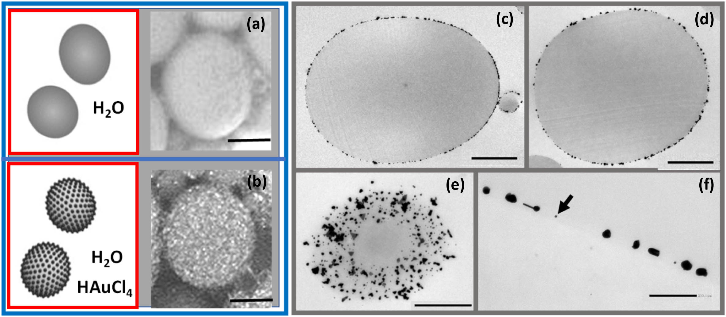
Fig. 1. (a) and (b) Sketches and SEM images of NMPs and AuNMPs; scale bars 2 μm; (c) and (d) TEM images of thin central sections of different AuNMPs; scale bars 2 μm; (e) TEM image of a section near to the edge of an AuNMP; note the AuNPs’ distribution on the surface; scale bar 1 μm. (f) AuNPs located at the NMP surface, magnification of (c); scale bar 200 nm.
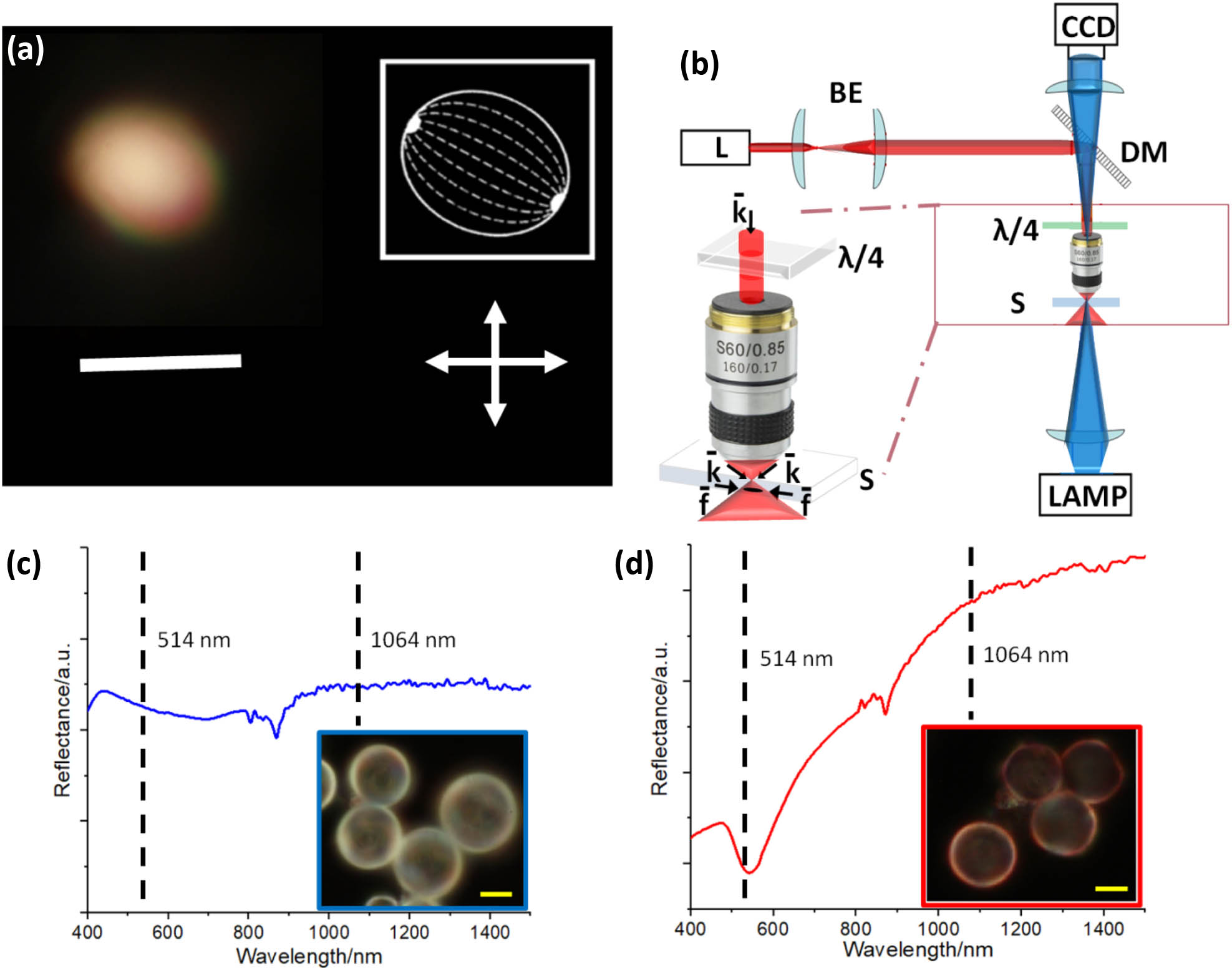
Fig. 2. (a) Optical microscope transmission image of an NMP between crossed polarizers; scale bar 5 μm. In the inset, the bipolar configuration scheme is shown. (b) Optical tweezers scheme. L, laser source; BE, beam expander; CCD, camera; DM, dichroic mirror; λ / 4 k f
Fig. 3. (a) Sequence of snapshots for a spinning bare NMP when irradiated by a left circularly polarized beam. The blue line represents the long axis of the ellipsoidal NMP. The yellow scale bar is 3 μm. (b) Track of the central position of a bare NMP which undergoes five full spinning rotations. (c) Spin frequency dependence of a bare NMP (average radius 2.8 μm) versus beam intensity, at 514 nm (magenta) and 1064 nm (black).
Fig. 4. (a) Sequence of snapshots for a spinning AuNMP when irradiated by a left circularly polarized beam. The red line represents the long axis of the ellipsoidal AuNMP. The yellow scale bar is 3 μm. (b) Track of the central position of the AuNMP, which undergoes five full spinning rotations. (c) Spin frequency dependence versus beam intensity of 3.2 ± 0.2 μm 2.8 ± 0.2 μm
Fig. 5. (a) Rotational kinetic energy of the bare NMPs (blue solid squares) and AuNMPs (red solid squares) as a function of the light intensity at 1064 nm. Rotational frequencies versus particle radius for (b) NMPs and (c) AuNMPs irradiated at 1064 nm and 1.7 mW / μm 2 1.7 mW / μm 2 3 ). The fit parameters used are the following: (b) P = 50 mW σ in = 0.90 α eff = 100 m − 1 Δ n = 0.13 P = 50 mW σ in = 0.90 α eff = 230 m − 1 Δ n = 0.13 P = 87 mW σ in = 0.90 α eff = 120 m − 1 Δ n = 0.16


Set citation alerts for the article
Please enter your email address

© Copyright 2018-2021 | Chinese Laser Press. All Rights Reserved 沪ICP备15018463号-20