
Nicola Pellizzi, Alfredo Mazzulla, Pasquale Pagliusi, Gabriella Cipparrone, "Plasmon-enhanced rotational dynamics of anisotropic core-shell polymeric-metallic microparticles," Photonics Res. 10, 2734 (2022)
- Photonics Research
- Vol. 10, Issue 12, 2734 (2022)
Abstract
1. INTRODUCTION
The optical manipulation of small particles represents an important tool and a very flexible method for the investigation of processes at the micro- and nano-scale [1–5], as well as for technological development of driving micromachines [6–11]. Their features enable applications in several fields ranging from cell surgery and microinjection to microrheology. Taking advantage of complex structures of the light beam, many objects can be manipulated through multiple traps configurations [12], and their spinning and orbital motion can be simultaneously controlled through light beams with the proper phase profile [13–17]. Nevertheless, the use of Gaussian beams in simplified geometries enables easier and wider applications. In this view, the fabrication of complex micro- and nano-objects that undergo multiple motions when illuminated with light can offer several opportunities for mechanics at small scale.
Rotation at the microscale has been largely investigated [18]. Microrheology has gained several advantages from these studies, with applications in several fields ranging from hydrodynamics to biology. Also, micromechanics and microrobotics can achieve great advances in developing micromotors and microrotors with remote control. Birefringent particles were first investigated, since their spinning can be easily controlled by the optical torque induced by polarized light [19,20]. However, the magnitude of the torques that can be exerted by light to birefringent particles is small.
Recent investigations have demonstrated that spherical nanoparticles (NPs) with eccentric core-shell geometry can be used to generate considerable optical torques and then rotation rates, opening opportunities for nanorheology and biophotonics [21]. Indeed, core-shell microparticles (MPs) exhibit exceptional properties resulting from the proper combination of the inner and outer materials as well as from the size and geometry of the structures [22–28].
Sign up for Photonics Research TOC. Get the latest issue of Photonics Research delivered right to you!Sign up now
Recently, we have developed a method to generate core-shell MPs composed of a polymeric liquid crystal core and a shell of gold nanoparticles (AuNPs) [29]. Our approach relies on the combination of two processes occurring during UV exposure of reactive mesogenic emulsion: (1) photopolymerization of mesogenic droplets (which constitute the solid cores) created in water; (2) photoreduction of chloroauric ions and precipitation of AuNPs that aggregate on the surface of the polymeric core in a raspberry-like structure. In our previous work, a chiral mesogen has been exploited as polymeric core [29], which results in spherical MPs with a spherulitic cholesteric arrangement [30]. Such configuration has demonstrated opportunities for photonic applications as Bragg onion resonators and the AuNPs’ shell improves lasing performances of the dye-doped MPs [29].
Here the method is applied to nematic reactive mesogens (RMs) droplets, to create core-shell MPs with an anisotropic core, both in the shape and in the optical properties. Indeed, based on the bipolar supramolecular arrangement of the nematic director inside the droplets, the core acquires an ellipsoidal shape. We demonstrate the improved performances introduced by the Au nanoshell in the optomechanical behavior of these MPs. Rotational dynamics of the nematic core-shell MPs induced by a circularly polarized Gaussian beam has been investigated and compared with the bare polymeric nematic MPs (NMPs). While simple spinning is observed for the latters, the formers undergo more complex motion. Peculiarities, motivations, and advantages are discussed.
2. CORE-SHELL MICROPARTICLES
A. Preparation and Characterization
The MPs are prepared via light-induced polymerization of nematic RMs droplets in pure water (bare NMP) or in a chloroauric acid aqueous solution (AuNMPs). Due to the RMs’ hydrophobicity, nematic droplets can be obtained by emulsification process in water. The uniaxial nematic phase has a symmetry axis defined by the so-called nematic director
The pure RMs mixture is obtained by extracting the solvent (propylene glycol monomethyl ether acetate, PGMEA) from the Licrivue RMS03-001C (Merck, Germany) solution using vacuum evaporation at 90°C overnight. NMP emulsions are prepared by adding 0.4% (mass fraction) of the nematic RMs to ultrapure (Type I) water. The glass vial containing the mixture is then heated at 100°C and shaken at 22 r/min for 30 s in a laboratory vortex mixer in order to obtain particles with a micrometric size, suitable for the present study. By properly setting the frequency and time of shaking, submicrometric particles can be also obtained. The AuNPs shell on the NMPs is obtained by mixing the emulsion with an equivalent volume of water containing chloroauric acid (
Scanning electron microscopy (SEM) measurements are performed using an FEI-Philips ESEM-FEG Quanta 200F apparatus operating at a range of 5–20 kV with a working distance of 6–15 mm.
In Figs. 1(a) and 1(b), the SEM images of the NMPs and AuNMPs are reported, respectively. The image in Fig. 1(b) clearly shows the presence of AuNPs over the polymeric MPs’ surface, forming a raspberry-like structure. A large heterogeneity of the MPs’ size, whose diameter ranges from 1 to 20 μm, is observed in both cases and is due to the microemulsification process. The mean diameter is
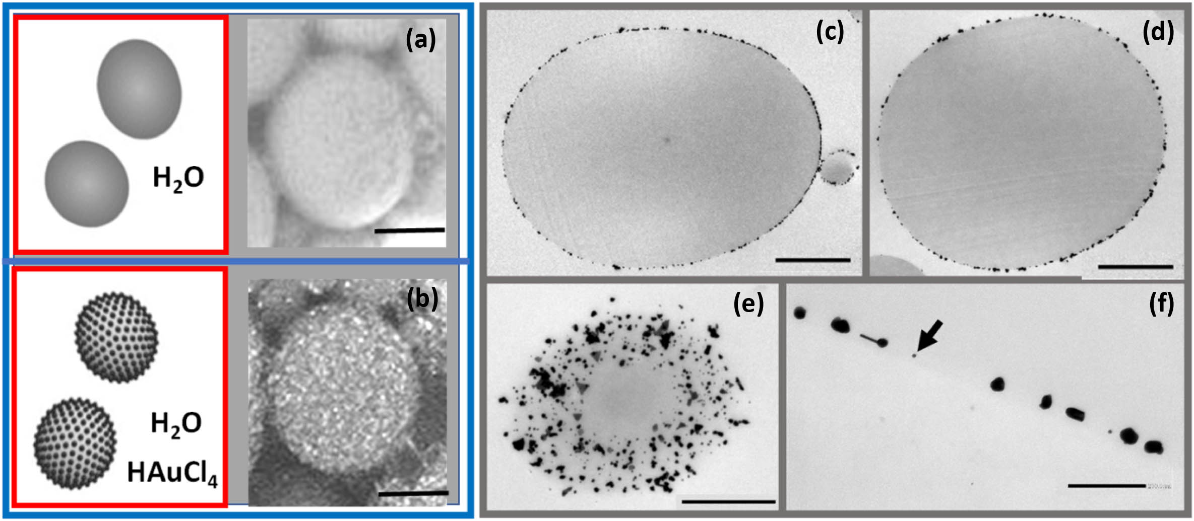
Figure 1.(a) and (b) Sketches and SEM images of NMPs and AuNMPs; scale bars 2 μm; (c) and (d) TEM images of thin central sections of different AuNMPs; scale bars 2 μm; (e) TEM image of a section near to the edge of an AuNMP; note the AuNPs’ distribution on the surface; scale bar 1 μm. (f) AuNPs located at the NMP surface, magnification of (c); scale bar 200 nm.
Transmission electron microscopy (TEM) has been carried out to investigate the shape of the MPs and the distribution of the AuNPs. The AuNMPs are first embedded in an epoxy resin (Araldite, Fluka) and successively cut into 100-nm-thick sections by means of a diamond knife. The ultrathin sections are collected on copper grids and are then examined with a Zeiss EM10 TEM at 80 kV acceleration voltage. In Figs. 1(c) and 1(d), central sections of AuNMPs are reported; they make evidence of their ellipsoidal shape and allow evaluating the length of the two axes. For both particles in Fig. 1(c), the short-to-long axis ratio is about 0.75, while for the particle in Fig. 1(d), it is 0.82. An evaluation of this ratio for both kinds of spheroidal NMPs (i.e., with and without the AuNPs shell) shows that its value is independent from the AuNPs’ coverage and ranges from 0.75 to 0.95. Figures 1(c) and 1(d) also clearly show that AuNPs aggregate around the polymeric core. The TEM image in Fig. 1(e) shows a section of an AuNMP, which has been sliced close to the edge of the particle: the image displays a larger section of the shell that visualizes the distribution of the AuNPs over the NMPs’ surface. Clusters of AuNPs, of different shapes and sizes, are almost uniformly distributed around the polymeric core. A magnification of the shell section is reported in Fig. 1(f), where both spherical AuNPs (see the arrow in the figure) and clusters can be clearly seen, of about 10 nm and 30–50 nm in size, respectively.
Optical polarizing transmission microscopy has been carried out by a Zeiss Axioscope to investigate the optical features of bare and core-shell NMPs. Between crossed polarizers, both kinds of MPs appear bright when the axes of the ellipse are not parallel to the polarizers’ one [i.e., at 45°, as in Fig. 2(a)]. This demonstrates that NMPs are birefringent, with the optical axis parallel to the major axis of the ellipsoid, as expected, considering the bipolar schematic representation of the molecular director within the polymeric NMPs [31].
![]()
Figure 2.(a) Optical microscope transmission image of an NMP between crossed polarizers; scale bar 5 μm. In the inset, the bipolar configuration scheme is shown. (b) Optical tweezers scheme. L, laser source; BE, beam expander; CCD, camera; DM, dichroic mirror;
Comparative UV-NIR spectroscopy is carried out on both kinds of NMPs, collected on glass substrates. Reflectance spectra of the two specimens are acquired by a Cary 5E spectrophotometer equipped with an integrating sphere. The reflectance spectra in Figs. 2(c) and 2(d) show a noticeable difference in the investigated spectral range that can be clearly ascribed to the presence of AuNPs shells. Indeed, the bare NMPs exhibit an almost flat reflectance over the whole spectral range, while the AuNMPs’ spectrum has a clearly different trend, with a substantial increase in the red-NIR region (above 600 nm) due to the Au shell. Moreover, the evident depletion around 550 nm could be associated to the plasmonic resonance of the AuNPs embedded in the polymeric surface [29].
3. OPTOMECHANICS
When an MP is illuminated by a tightly focused laser beam, optical trapping and manipulation can be performed thanks to the optical force
In the case of absorbing or reflecting particles, a large radiation pressure is generally produced, and the particles are pushed out from the irradiated region [34,35], preventing the optical trapping.
Rotational motion is produced by the transfer of angular momentum from the light to the particles, in the form of spin angular momentum (SAM), related to the light polarization (circular), or orbital angular momentum (OAM), associated with the light wavefront shape [13,18].
Particles features also allow this transfer: absorbing particles or particles with anisotropic shape, like the ellipsoidal ones, or with anisotropic optical properties (like birefringence), can experience a torque due to SAM transfer. In these cases, spinning is typically induced, while light with OAM (Laguerre–Gauss, Bessel beams, etc.) generates orbital motion (Ref. [18] and references therein). In all cases, the spin and orbital velocities result from the balance between the optical and the viscous torques and forces [18,19].
Based on their anisotropic shape and optical properties, both bare and core-shell NMPs are expected to rotate. The present study is aimed at comparing the rotational motions produced in the same experimental condition for both kinds of NMPs, addressing the role of their different optical properties (see Fig. 2).
A. Optical Tweezer Setup
A standard optical tweezers setup, based on Gaussian laser beams, is employed, as shown in Fig. 2(b). In order to investigate the optomechanical behavior of the AuNMPs in the spectral regions where they display the main differences with respect to the bare NMPs, two continuous wave laser sources are used. An argon-ion laser (Innova 90c, Coherent) at
The sample position is adjusted by a three-axis translation stage. A fiber illuminator and a charge-coupled device (CCD) camera are used to illuminate and image the sample.
The longitudinal position of the laser beam focus with respect to the sample chamber is adjusted to provide a 2D trapping of the NMPs close to the bottom chamber surface. The optical force has a component perpendicular to the beam axis, mainly induced by the gradient of the intensity beam profile [force
The beam radius at the sample plane is estimated to be about 7 μm for the argon laser (514 nm) and about 10 μm for the Nd:YAG (1064 nm).
B. Rotational Motion of Bare NMPs
Rotational motion has been investigated by means of optical tweezers [Fig. 2(b)]. Birefringent dielectric MPs can be easily trapped due to a gradient force; moreover, also SAM transfer from light to particles is allowed, which produces a reaction torque [18,37]. Then, when they are trapped by circularly polarized light into the region of highest intensity (i.e., the axis of the Gaussian beam), they undergo a continuous spinning. The exerted optical torque [20] induced by the change of the beam’s photon polarization state
The trapped particle reaches a steady state when the optical torque
For a nonspherical particle also a shape-induced birefringence contribution has to be considered; the torque arises due to the asymmetric scattering forces when the principal axis of the particle is not parallel to the light’s electric field [38].
Bare NMPs are weakly trapped on axis with the laser beam, for both visible and near-IR wavelengths. Spin rotation occurs clockwise or counterclockwise, according to the handedness of the circularly polarized light.
In Fig. 3(a), a frames sequence (extracted from video 1, see
![]()
Figure 3.(a) Sequence of snapshots for a spinning bare NMP when irradiated by a left circularly polarized beam. The blue line represents the long axis of the ellipsoidal NMP. The yellow scale bar is 3 μm. (b) Track of the central position of a bare NMP which undergoes five full spinning rotations. (c) Spin frequency dependence of a bare NMP (average radius 2.8 μm) versus beam intensity, at 514 nm (magenta) and 1064 nm (black).
In Fig. 3(c), the rotational frequencies of NMPs with similar mean radius (
Higher rotational frequency is observed for the longer radiation wavelength in the same range of power density, according to Eq. (1). The slopes of the best fit lines, as reported in Fig. 3(c), are
C. Rotational Motion of AuNMPs
Under the same visible and near-IR circularly polarized laser irradiation, core-shell AuNMPs undergo different rotational dynamics with respect to the bare NMPs, which can be accounted for by the peculiar optical properties introduced by the metallic NPs shell. First, the equilibrium position relocates from the beam axis to an annular region around it, whose radius is almost independent from the beam intensity. Only above a certain intensity value (i.e., about 4.0 and
![]()
Figure 4.(a) Sequence of snapshots for a spinning AuNMP when irradiated by a left circularly polarized beam. The red line represents the long axis of the ellipsoidal AuNMP. The yellow scale bar is 3 μm. (b) Track of the central position of the AuNMP, which undergoes five full spinning rotations. (c) Spin frequency dependence versus beam intensity of
Comparing these measurements with the ones of the bare NMPs proves that the presence of a shell of AuNPs around the polymeric NMP boosts the rotational dynamics at both beam trap wavelengths. The rotational frequency enhancement is even more distinct for the 514 nm beam; the fitting line slope [Fig. 4(c)] is here
Starting from the above considerations, we discuss the observed dynamics and relate it to the optical and geometrical features of the NMPs, as well as to the trapping configuration.
The bare NMPs are confined in a plane near the bottom glass substrate. For this trapping geometry, the longitudinal scattering force is reduced, while the transverse gradient force exerted by the laser beam confines the NMPs on its axis, where they spin due to the SAM transfer of the circularly polarized light. Preventing 3D trapping that would align the ellipsoidal particle along the beam axis [40], the NMPs orient with the major axis parallel to the glass substrate (exhibiting a larger birefringence) and rotate around a minor axis parallel to the beam’s one.
On the other hand, we observe that the AuNPs’ shell significantly alters the entrapment position and the motion of the AuNMPs. For the 1064 nm laser source wavelength, due to the AuNMPs’ increased reflectance, the scattering force contribution is expected to increase in the propagation direction (wave vector
Such AuNMP trapping is observed until the longitudinal component of the force becomes relevant, and after that the particle is expelled from the trap; this effect occurs for light intensities above
The shell reflectance also affects the rotational motion. Due to the circular polarization of the light beam, the particle rotates around its minor axis and contextually moves on a circular trajectory, displaying an orbital motion that cannot be accounted for by the OAM of the light beam. A plausible explanation could be put forward considering the optical forces in the transverse plane and the SAM transfer. When the particle starts to rotate, it also moves along the orbit, following its equilibrium position in the annular trap. Based on this feature, at any orbit position the particle has the same orientation with respect to the beam center [see Fig. 4(a)], giving evidence of a synchronous rotation. By consequence, the orbital motion is triggered by the ellipsoidal AuNMPs’ spinning within the specific trapping potential field.
In Fig. 5(a), the kinetic energy as a function of the light intensity, at 1064 nm wavelength, is reported for a bare NMP and an AuNMP with the same radius (2.8 μm). Although the trend is linear for both NMPs, the slope is steeper for the AuNMPs, suggesting the occurrence of an additional contribution to the optical torque in Eq. (2). Since no transfer of angular momentum is expected due to the reflection at the water/AuNMP interface, we can assume that the increased reflectance at the interface between the dielectric core and the AuNPs’ shell favors a greater circulation of light within the AuNMPs, which is responsible of the increased optical torque, and consequently of the higher rotational frequency with respect to the bare NMPs. Such interpretation is supported by the rotational frequency measurements of the NMPs and AuNMPs as a function of the particle radius, at 1064 nm laser wavelength and
![]()
Figure 5.(a) Rotational kinetic energy of the bare NMPs (blue solid squares) and AuNMPs (red solid squares) as a function of the light intensity at 1064 nm. Rotational frequencies versus particle radius for (b) NMPs and (c) AuNMPs irradiated at 1064 nm and
The fitting curves in Figs. 5(b) and 5(c) account for the enhanced optical torque on the AuNMPs associated with their doubled effective absorption (
A greater contribution to the rotational frequency of the AuNMPs and, consequently, to the kinetic energy, is obtained for the 514 nm laser beam. In Fig. 5(d), the acquired rotational kinetic energy as a function of the light intensity is reported for a bare NMP and an AuNMP of comparable size. A more efficient angular momentum transfer from the absorption-mediated process enables one to increase the rotational kinetic energy of the core-shell AuNMPs by two orders of magnitude with respect to the bare NMPs. Looking at the spectra in Fig. 2, the optical properties at 514 nm suggest the optical torque enhancement as the only responsible of the rotational frequency increase due to the photons absorbed by the plasmonic nanoshell; see Figs. 3(c) and 4(c). Moreover, compared to 1064 nm wavelength, plasmonic resonance and lower reflectance at 514 nm are clearly observed (Fig. 2).
In Figs. 5(e) and 5(f) the frequency is reported as a function of the particle’s radius. While for bare NMPs, the trend is the one described by Eqs. (1) and (2), the AuNMPs exhibit a different behavior, being stably trapped only if their radius is larger than 3 μm. Here, the optical force is expected to have a further contribution due to the transferred linear momentum from the absorbed light, which is opposite to the one due to the refracted rays [1,34] and reduces the trap stability. Nevertheless, due to the core-shell structure, the absorption process does not involve the whole MP, but only the thin AuNPs shell. Hence, for large values of the surface-to-volume ratio (i.e., for smaller particles) at fixed surface density of the AuNPs, this contribution is expected to prevail, pushing the AuNMPs out of the irradiated region. With the increase of the particle radius, this effect reduces, thus enabling stable trapping within an annular region, at even higher light intensity values with respect to the 1064 nm beam; see Fig. 4(c).
The absorbed photons, different from the reflected one, may transfer SAM, giving a further contribution to the optical torque applied to the particle [18]. Such a contribution compensates for the lower values of the rotational frequency at 514 nm, as expected from Eqs. (2) and (3). The graph in Fig. 4(c) shows that, for particles with
Beside the ones investigated in the present work, further advantages of the core-shell structure could be linked to the heating phenomena caused by light absorption. Such side effects must be usually avoided, since the structural modifications that the temperature increase may induce in both the environment and/or the MP itself limit the power value that can be used and the rotation rates that can be achieved [43]. Here, the resonant absorption involving the AuNPs in the nanometric shell is able to significantly enhance the optical torque on the MPs, whereas the core-shell structure reduces the temperature rise of the whole particle and improves the heat dissipation processes.
4. CONCLUSION
We demonstrate that the dielectric-metallic core-shell structure of birefringent MPs enhances the rotational rates and enables further rotational modes in a basic Gaussian beam optomechanical setup. The comparative investigation between bare NMPs and AuNMPs, at different beam wavelengths, rationalizes the rotational dynamical features of the latter in term of the optical properties of the AuNPs shell.
The increased reflectance expressed in the near-IR region (at 1064 nm) modifies the rotational motion: bare NMPs spin, while the AuNMPs show a synchronous spinning and orbital motion. The efficient absorption expressed in the visible region at the plasmonic resonance of the AuNPs (at 514 nm) also enhances the rotational rates that can be achieved exploiting the same light intensity: the core-shell AuNMPs exhibit a rotational kinetic energy that is two orders of magnitude larger than the bare NMPs one. Finally, the core-shell structure also could represent a useful approach to limit the heating side effects generally linked to the light absorption. Therefore, the reported results reveal a novel strategy to improve the rotational control of MPs and can have direct implications in applications involving light-guided rotating micro-objects, like micromechanics (micromotors and microrotors) and microrheology.
Acknowledgment
Acknowledgment. The authors would like to thank Dr. Ida Perrotta (Department of Biology, Ecology and Earth Sciences, University of Calabria) for the TEM measurements, Prof. Nicola Scaramuzza (Department of Physics, University of Calabria) for the access to the spectrophotometer, and Dr. Giovanni Desiderio (Institute of Nanotechnologies, CNR) for useful discussions.
References
[2] K. Dholakia, T. Čižmár. Shaping the future of manipulation. Nat. Photonics, 5, 335-342(2011).
[3] S. E. S. Spesyvtseva, K. Dholakia. Trapping in a material world. ACS Photon., 3, 719-736(2016).
[8] J. Glückstad, D. Palima. Light Robotics: Structure-Mediated Nanobiophotonics(2017).
[11] Y. Sun, S. Zhang, F. Nan, X. Wang, S. L. Neale, J. Yu. Light-driven microrobots: mechanisms and applications. Field-Driven Micro and Nanorobots for Biology and Medicine, 91-111(2022).
[13] M. Padgett, R. Bowman. Tweezers with a twist. Nat. Photonics, 5, 343-348(2011).
[31] S. Paparini, E. G. Virga. Nematic tactoid population. Phys. Rev. E, 103, 22707(2021).
[36] K. C. Neuman, S. M. Block. Optical trapping. Rev. Sci. Instrum., 75, 2787(2004).


Set citation alerts for the article
Please enter your email address

© Copyright 2018-2021 | Chinese Laser Press. All Rights Reserved 沪ICP备15018463号-20