
Krishna Murari, Giovanni Cirmi, Hüseyin Cankaya, Gregory J. Stein, Benoit Debord, Frederic Gérôme, Felix Ritzkosky, Fetah Benabid, Oliver Muecke, Franz X. Kärtner, "Sub-50 fs pulses at 2050 nm from a picosecond Ho:YLF laser using a two-stage Kagome-fiber-based compressor," Photonics Res. 10, 637 (2022)
- Photonics Research
- Vol. 10, Issue 3, 637 (2022)
Abstract
1. INTRODUCTION
High-energy ultrashort mid-infrared (mid-IR) laser radiation is of vast importance due to its wide applications ranging from spectroscopy [1] and high-speed electronics to attoscience phenomena and strong-field physics. Tabletop attosecond light sources rely on high harmonic generation (HHG) when a few-cycle intense laser pulse interacts with noble gases in vacuum. Until now, Ti:sapphire lasers centered at 800 nm have been the major workhorse for driving the HHG to generate isolated attosecond pulses in 10s of eV range. Scaling of the photon energies by HHG beyond 100 eV or to the keV range requires the development of high-energy few-cycle lasers at longer wavelengths for driving the HHG process. It is well known that the cutoff energy of the HHG scales quadratically with the wavelength according to
Generation of an intense few-cycle mid-IR pulse is achieved using the optical parametric amplifier (OPA) or optical parametric chirped-pulse amplifier (OPCPA). When properly scaling the pulse energy to the multi-mJ level, they even permit the realization of bright coherent table-top HHG sources in the water-window and keV X-ray region [19,20]. However, access to long wavelengths beyond 4 μm is limited, as the pump source of these OPCPA relies mostly on the near-IR wavelength at 800 nm or 1 μm. This is mainly due to the use of oxide crystals for frequency conversion that are not transparent beyond 4 μm and low quantum efficiency due to unfavorable quantum defects at the longer wavelength. Non-oxide crystals such as ZGP,
The commonly used approach to broaden the output spectrum from a CPA laser is nonlinear spectral broadening in waveguides followed by dispersion compensation. When an intense ultrashort laser pulse propagates in an optical waveguide, it gives rise to several intensity-dependent nonlinear effects such as self-phase modulation (SPM), stimulated Raman scattering (SRS), and four-wave mixing (FWM). These processes give rise to new frequencies, and with proper dispersion management, pulses shorter than the input are generated. Nonlinear pulse compression can be implemented in several schemes such as in bulk dielectric media [24,25], a multi-pass gas cell [26,27], or a hollow-core waveguide [28,29], but each of them has its limitation; hence, their usage relies on the application. For instance, broadening in bulk media suffers from modal instabilities and pulse breakup at high energies. Nonlinear spectral broadening in noble gas-filled hollow-core capillary fiber (HCF) and dispersion management externally achieved a breakthrough with the invention of chirp mirrors [30], which allowed compact and precise control of dispersion. It is noteworthy that the HCF consists of a glass capillary, not to be confused with an optical fiber. Since then, large-core diameter HCFs are routinely used to generate few-cycle pulses at 800 nm with pulse energies in mJ range. However, their large core structure leads to high bending loss, thereby requiring the fiber to be kept straight for the entire length of the fiber and making them highly prone to the environmental conditions. In addition, they have a very low transmission efficiency (
Sign up for Photonics Research TOC. Get the latest issue of Photonics Research delivered right to you!Sign up now
In recent years, nonlinear compression in Kagome fiber at 800 nm or 1030 nm wavelengths [40,41] has seen rapid progress for both high-energy [36,42] and high-average-power systems [43]. Very few self-compression experiments have been demonstrated at wavelengths near 2 μm with the input pulse duration ranging from a few 10s to a few 100s of fs. Balciunas et al. achieved remarkable self-compression of 80 fs pulses down to the single-cycle limit at 1.8 μm with output pulse energies of 25 μJ [44]. Moreover, regardless of the pump wavelength, compression of pulses starting from ps duration is extremely challenging and has been rarely reported. There exist few demonstrations with an input pulse duration of 6 ps [45] and 27 ps [46] at 1030 nm, but the main goal of these experiments was rather different and geared toward Raman scattering instead of pulse compression. First, picosecond compression at 2 μm wavelength was demonstrated by Murari et al. by compressing 3.3 ps pulses to 285 fs [47]. Here, we present generation of sub-50 fs pulses from the ps output of a Ho:YLF-based chirped pulse amplifier (Ho-CPA) system at 2 μm by utilizing two-stage nonlinear compression. This simple, compact, and robust high-energy system at 2 μm can serve as a laser driver for HHG in solids and it enables passively CEP stable idler wave for the two-color HHG experiments as shown in Fig. 1. The pump chain consists of a Ho-fiber oscillator, Ho:YLF regenerative amplifier (RA), and chirp volume Bragg grating (CVBG) for pulse stretching and compression. The Ho-CPA operates at a 1 kHz repetition rate, and a small portion energy of 140 μJ is sent into a two-stage nonlinear compressor; the remaining energy of
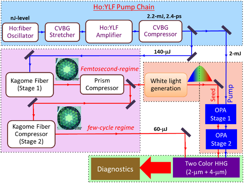
Figure 1.Proposed scheme of two-color HHG driven by Ho-CPA as front-end.
2. EXPERIMENTAL SETUP
A. Ho:YLF Laser Amplifier
The high-energy picosecond pump pulses are derived from Ho-CPA with a homebuilt Ho-fiber oscillator and a commercial Ho:YLF RA from Q-Peak Inc. The schematic of the laser source is depicted in Fig. 2. The Ho-fiber oscillator emits pulses at 34 MHz repetition rate with a pulse energy of 1 nJ and a duration of 160 fs. The output spectrum is centered at 2060 nm with a spectral bandwidth of 37 nm full width at half-maximum (FWHM). The oscillator pulses are stretched in a CVBG from OptiGrate Inc. to 300 ps, and due to the filtering effect in CVBG, the seed bandwidth before amplification reduces to 8.2 nm FWHM. The stretched pulses are amplified in the RA and a single-pass booster both based on Ho:YLF crystals, which are end-pumped by a Tm-fiber laser at 1940 nm. After amplification, the spectral bandwidth of the output spectrum reduces from 8.2 nm to 2.3 nm, which is compressed using the same CVBG as used for stretching. At the output, the pulse energy of 2.2 mJ with the duration of 3.5 ps FWHM is achieved. However, we found that this pulse duration was somewhat longer than that required for suppressing pulse break in the first Kagome fiber compressor as described in the next subsection. Therefore, we explored a method to shorten the pulse duration of the output pulse from the Ho-CPA system by mitigating the gain-narrowing (GN) effect in the RA.
![]()
Figure 2.(a) The schematic layout of the Ho-CPA based on Ho:fiber oscillator, amplifier, and chirp volume Bragg grating (CVBG)-based stretcher and compressor with half-wave plate (
To reduce the GN-effect during the amplification in the RA, we insert an optimized etalon inside the RA cavity. The etalon acts as an anti-GN frequency-selective filter that enhances the output spectrum, leading to the shortening of the pulse duration. An etalon has a sinusoidal transmission function whose period depends on thickness, the modulation depth depends on reflectivity, and the phase depends on the angle of incidence. Hence, by careful choice of thickness, reflectivity and phase of the etalon, the effect of GN after each round trip is reduced thereby increasing the effective output spectrum. The angle of the etalon is tuned in such a way that its transmission minimum is aligned with the gain maximum. With the use of fused silica etalon of thickness 290 μm and reflectivity 3.3%, the spectral bandwidth is increased from 2.9 nm to 5.4 nm. The complete optimization of the gain shaping using an etalon can be found in Ref. [48]. After etalon optimization, the Ho-CPA is operated at a lower pulse energy of 1.7 mJ with a pulse duration of 3.3 ps (without etalon) and 1.8 ps (with etalon).
B. Dual-Stage Kagome-Fiber-Based Compressor
Our nonlinear dual-stage compressor consists of Kagome fiber based on a hypocycloid-core-contour (7-cell and 19-cell) specially designed for operation at 2-μm wavelength in the anomalous dispersion regime. The fiber is fabricated by the GPPMM group in France. The 7-cell fiber has an inner core diameter of 63 μm with mode field diameter (MFD) of 44 μm and NA of 0.018 while the 19-cell fiber has an inner core diameter of 82 μm, MFD of 54 μm, and NA of 0.014. It also has a very broad transmission range of 400–2400 nm and exhibits a relatively low propagation loss of 0.2 dB/m at 2 μm. The calculated group velocity dispersion (GVD) of the fiber at 2 μm is low and anomalous with a value of
We initially launched the pulses in a 19-cell fiber with a length of 3.5 m and high-energy up to 780 μJ at 3.3 ps duration. From the exit end of the fiber, inert gas Ar at a pressure of 3 bar is injected. Figure 3(a) shows the waterfall plots of spectral broadening obtained at the output of the fiber with increasing input energy from 85 μJ to 780 μJ beyond which fiber damage is observed. The spectrum is measured using the NIRQuest grating spectrometer from Ocean Optics Inc. that has high resolution of 1.5 nm and spectral range from 1850 to 2150 nm. As the energy is increased, the pulse encounters very limited broadening due to the generation of the high order soliton leading to soliton fission. Due to the ps-long input pulse the soliton order
![]()
Figure 3.Measured spectral evolution at the output of the Ar-gas filled 19-cell Kagome fiber at a pressure of 3 bar with an increasing input energy at a pulse duration of 3.3 ps (left) and 1.8 ps (right).
In the first stage, a pulse energy of 140 μJ is launched into a 7-cell Kagome fiber of length 3 m using a mode-matched lens of focal length 50 mm. For all further experiments, we only use the 7-cell fiber instead of the 19-cell fiber. The incoupling end of the fiber is mounted on a metal V-groove and left open in ambient air, while the outcoupling end is capped in a high-pressure gas cell with a 5-mm-thick uncoated
![]()
Figure 4.Experimental layout of the two-stage compression in 7-cell Kagome fiber: the first stage comprises spectral broadening in the fiber of length 3 m and a prism compressor whose tip-to-tip separation is 1.1 m. The output of the first stage is launched in the second piece of Kagome fiber and self-compressed with the outer end placed in the gas cell. The GDD of the thin window of the gas cell is used to compensate for the small positive chirp remaining in the fiber.
3. RESULTS AND DISCUSSION
A. Pulse Dynamics and Modulation Instability
Though the main mechanism of spectral broadening in PCF is SPM, the dynamics can vary significantly with the input pulse duration and the fiber parameters as different higher-order nonlinear effects can play a crucial role. Broadly, the pulse duration is classified into two regimes: an ultrashort fs-regime and a longer ps-regime. For this reason we divided the experiments into two stages. In the first stage, the pulses are in ps-regime, while in the second stage they are in fs-regime. In particular, the pulse dynamics varies significantly with the position of the input pulse wavelength relative to the zero-dispersion wavelength (ZDW). Regardless of the input pulse duration, when operating in the normal dispersion regime, the spectral broadening in both fs- and ps-regimes is heavily dominated by SPM. However, when operating in anomalous dispersion, in addition to SPM, more complex physics is involved, which is dominated by soliton-related dynamics. Depending on the input peak intensity, either solitonic self-compression occurs or, if the peak intensity is high, soliton fission occurs in which the pulse with sufficient peak power breaks up into a series of lower power sub-pulses due to the perturbation of higher-order dispersion or Raman scattering. The pulse breakup is generally linked to the soliton order (
Table 1 summarizes the calculation of the
Calculated Dispersion Length
| Argon-5 bar | Krypton-5 bar | Air-1 atm | |||||
|---|---|---|---|---|---|---|---|
| 3300 | 4644 | 0.26 | 134 | 0.08 | 239 | 1.62 | 54 |
| 1800 | 1382 | 0.14 | 99 | 0.04 | 176 | 0.88 | 40 |
| 285 | 35 | 0.03 | 32 | 0.01 | 56 | 0.22 | 13 |
B. Pulse Characterization
The optical pulses are characterized using a home-built second-harmonic generation-frequency-resolved optical gating (SHG-FROG) setup employing a 200-μm-thick BBO crystal. The results of these measurement can be found in Ref. [47]. The FROG retrieval of the pulses at the output of the first stage yields a duration of 285 fs with the FL of 244 fs. To achieve further compression, the 285 fs pulse obtained from the first stage is launched into the second stage fiber. Since, in the first stage, the ps pulse from the Ho-CPA is reduced to 285 fs and the pulse duration at the input of the second stage is in the fs-regime, the
![]()
Figure 5.(a) Measured spectral evolution obtained at the output of the second stage with increasing input pulse energy for three different gas conditions in the fiber: air at 1 atm pressure; Kr gas filled in the fiber at a pressure of 3, 4, and 5 bar. (b) Measured autocorrelation trace at the input of the first stage (red), input of the second stage (blue), output of the second stage (highlighted background) with different amount of negative GDD added to optimize the remaining chirp from the second stage fiber compressor.
The shortest output pulse with the autocorrelation value of 38 fs obtained in the presence of air is then characterized using the FROG, and the results are shown in Fig. 6. Figure 6(a) shows the measured FROG trace shown on full time scale while Fig. 6(b) shows the trace after filtering out the compressed part using super-Gaussian filter in the time domain where about 28% of the entire pulse energy is contained. This is done to avoid the numerical issues emerging from the high complexities of the FROG trace data between the long ps pulse in the background and the ultrashort component. The reconstructed FROG trace of the filtered trace in Fig. 6(b) is shown in Fig. 6(c). From the reconstruction, we obtain a 48 fs FWHM duration of the compressed component that contains 67% (
![]()
Figure 6.FROG results of output pulse from the second stage based on 7-cell Kagome fiber of length 2 m filled with air. (a) Measured FROG trace shown on the full time scale; (b) FROG trace after filtering out the compressed part using a super-Gaussian filter in the time domain; (c) reconstructed FROG trace retrieved from the filtered trace; (d) measured (red) and retrieved (black) spectrum with the retrieved spectral phase in blue; (e) retrieved temporal profile (black) and retrieved temporal phase (blue) overlaid with the simulated profile in the green dotted line.
Finally, we measure the pulse-to-pulse power stability of the overall system using a thermal powermeter PM10 from Coherent Inc. The output power from the second stage is directed to the powermeter, and simultaneously we measure the fluctuations from the Ho-CPA. Figure 7(a) shows the power stability measured at the output of the second stage (red) and from the amplifier (black) for 70 min with a root mean square deviation value of 0.22% and 0.42%, respectively. The amplifier is operated under humidity level
![]()
Figure 7.(a) Measured pulse-to-pulse fluctuations for 70 min at the output of the Ho-CPA (black) and after the second stage compression (red); (b) measured output spectra from the amplifier (black), after compression from the first stage Kagome fiber (red) and from the second stage Kagome fiber (blue).
C. Simulation
To understand the compression dynamics in the second stage Kagome fiber operated at 2 μm, we simulated the nonlinear pulse propagation in HC-PCF using a numerical model based on a 1D nonlinear Schrödinger equation given by
Here, the term
![]()
Figure 8.Simulation results after the second stage with a fiber length of 2 m and input pulse parameters obtained from the output of the first stage. (a) Spectral evolution along the fiber length; (b) temporal evolution along the fiber length, the white dashed line indicates the pulse exit point from the fiber; (c) simulated spectrum (red); (d) simulated temporal profile (red) obtained at the end of the fiber length, overlaid with the experimental profile (black).
D. White Light Generation Using 48 fs, 2 μm Pulses
The output pulse obtained after the second Kagome fiber stage is focused by an AR-coated lens of 50 mm focal length into a 3 mm thin YAG plate. Figure 9 shows the images of the generated white light captured with a camera for different input energy and the schematic of the setup. The input pulse energy is increased in steps from 10 μJ to 60 μJ in the energy increments of 10 μJ. The input energy is controlled using a TFP and an HWP.
![]()
Figure 9.White light generation in a thin YAG plate with pulses derived from the two-stage Kagome compressor for different input energies. The top panel shows the schematic of white light generation setup.
4. CONCLUSION
In summary, the Ho-CPA operates at 1 kHz repetition rate and delivers pulses at the mJ level and with durations in the few ps range. A small portion of the output energy is spectrally broadened in a first stage Kagome fiber and compressed using a silicon (Si) prism pair. With an input pulse energy of 140 μJ, the pulses are compressed to 285 fs with an output energy of 90 μJ. The output pulse is further spectrally broadened and self-compressed in a second stage air-filled Kagome fiber of 2 m length leading to pulse duration of 150 fs. With proper GDD compensation using a thin sapphire window of 3 mm, output pulses of 48 fs duration are obtained with a pulse energy of 60 μJ and 19% of the energy, i.e., 11 μJ, in the main peak. After compression of the picosecond pulses down to 48 fs in a two-stage Kagome compressor at 2 μm wavelength, we also generated white light with this compressed pulse that confirms the coherent nature of the compressed pulse and suitability for experiments. With only 140 μJ of energy used for compression, the system as envisioned in Fig. 1 allows pumping of the OPA with more than 2 mJ of energy. When focused to a spot size of 50 μm, the intensity of the output from the second stage can reach peak values of
Acknowledgment
Acknowledgment. We thank Oliver D. Mücke for helpful discussions in FROG reconstruction.
References
[1] H. Pires, M. Baudisch, D. Sanchez, M. Hemmer, J. Biegert. Ultrashort pulse generation in the mid-IR. Prog. Quantum Electron., 43, 1-30(2015).
[2] I. Jovanovic, G. Xu, S. Wandel. Mid-infrared laser system development for dielectric laser accelerators. Phys. Procedia, 52, 68-74(2014).
[3] H. R. Reiss. Limits on tunneling theories of strong-field ionization. Phys. Rev. Lett., 101, 043002(2008).
[4] S. Woutersen, U. Emmerichs, H. J. Bakker. Femtosecond mid-IR pump-probe spectroscopy of liquid water: evidence for a two-component structure. Science, 278, 658-660(1997).
[5] A. H. Chin, J. M. Bakker, J. Kono. Ultrafast electroabsorption at the transition between classical and quantum response. Phys. Rev. Lett., 85, 3293-3296(2000).
[6] S. Ghimire, A. D. DiChiara, E. Sistrunk, U. B. Szafruga, P. Agostini, L. F. DiMauro, D. A. Reis. Redshift in the optical absorption of ZnO single crystals in the presence of an intense midinfrared laser field. Phys. Rev. Lett., 107, 167407(2011).
[7] S. Ghimire, A. D. DiChiara, E. Sistrunk, P. Agostini, L. F. DiMauro, D. A. Reis. Observation of high-order harmonic generation in a bulk crystal. Nat. Phys., 7, 138-141(2011).
[8] O. D. Mücke. Isolated high-order harmonics pulse from two-color-driven Bloch oscillations in bulk semiconductors. Phys. Rev. B, 84, 081202(2011).
[9] G. J. Stein, P. D. Keathley, P. Krogen, H. Liang, J. P. Siqueira, C.-L. Chang, C.-J. Lai, K.-H. Hong, G. M. Laurent, F. X. Kärtner. Water-window soft X-ray high-harmonic generation up to the nitrogen K-edge driven by a kHz, 2.1 μm OPCPA source. J. Phys. B, 49, 155601(2016).
[10] J. Pupeikis, P.-A. Chevreuil, N. Bigler, L. Gallmann, C. R. Phillips, U. Keller. Water window soft X-ray source enabled by a 25 W few-cycle 22 μm OPCPA at 100 kHz. Optica, 7, 168-171(2020).
[11] X. Ren, J. Li, Y. Yin, K. Zhao, A. Chew, Y. Wang, S. Hu, Y. Cheng, E. Cunningham, Y. Wu, M. Chini, Z. Chang. Attosecond light sources in the water window. J. Opt., 20, 023001(2018).
[12] A. D. Shiner, C. Trallero-Herrero, N. Kajumba, H.-C. Bandulet, D. Comtois, F. Légaré, M. Giguère, J.-C. Kieffer, P. B. Corkum, D. M. Villeneuve. Wavelength scaling of high harmonic generation efficiency. Phys. Rev. Lett., 103, 073902(2009).
[13] M. B. Gaarde, K. J. Schafer, A. Heinrich, J. Biegert, U. Keller. Large enhancement of macroscopic yield in attosecond pulse train–assisted harmonic generation. Phys. Rev. A, 72, 013411(2005).
[14] F. Brizuela, C. M. Heyl, P. Rudawski, D. Kroon, L. Rading, J. M. Dahlström, J. Mauritsson, P. Johnsson, C. L. Arnold, A. L’Huillier. Efficient high-order harmonic generation boosted by below-threshold harmonics. Sci. Rep., 3, 1410(2013).
[15] G. Orlando, P. P. Corso, E. Fiordilino, F. Persico. A three-colour scheme to generate isolated attosecond pulses. J. Phys. B, 43, 025602(2010).
[16] A. Heinrich, W. Kornelis, M. P. Anscombe, C. P. Hauri, P. Schlup, J. Biegert, U. Keller. Enhanced VUV-assisted high harmonic generation. J. Phys. B, 39, S275-S281(2006).
[17] Z. Chang. Enhancing keV high harmonic signals generated by long-wave infrared lasers. OSA Continuum, 2, 2131-2136(2019).
[18] H. Du, L. Luo, X. Wang, B. Hu. Attosecond ionization control for broadband supercontinuum generation using a weak 400 nm few-cycle controlling pulse. Opt. Express, 20, 27226-27241(2012).
[19] T. Popmintchev, M.-C. Chen, D. Popmintchev, P. Arpin, S. Brown, S. Alisauskas, G. Andriukaitis, T. Balciunas, O. D. Mucke, A. Pugzlys, A. Baltuska, B. Shim, S. E. Schrauth, A. Gaeta, C. Hernandez-Garcia, L. Plaja, A. Becker, A. Jaron-Becker, M. M. Murnane, H. C. Kapteyn. Bright coherent ultrahigh harmonics in the keV X-ray regime from mid-infrared femtosecond lasers. Science, 336, 1287-1291(2012).
[20] S. Hädrich, M. Krebs, A. Hoffmann, A. Klenke, J. Rothhardt, J. Limpert, A. Tünnermann. Exploring new avenues in high repetition rate table-top coherent extreme ultraviolet sources. Light Sci. Appl., 4, e320(2015).
[21] P. Malevich, G. Andriukaitis, T. Flöry, A. J. Verhoef, A. Fernández, S. Ališauskas, A. Pugžlys, A. Baltuška, L. H. Tan, C. F. Chua, P. B. Phua. High energy and average power femtosecond laser for driving mid-infrared optical parametric amplifiers. Opt. Lett., 38, 2746-2749(2013).
[22] C. R. Phillips, J. Jiang, C. Mohr, A. C. Lin, C. Langrock, M. Snure, D. Bliss, M. Zhu, I. Hartl, J. S. Harris, M. E. Fermann, M. M. Fejer. Widely tunable midinfrared difference frequency generation in orientation-patterned GaAs pumped with a femtosecond Tm-fiber system. Opt. Lett., 37, 2928-2930(2012).
[23] D. Brida, M. Marangoni, C. Manzoni, S. De Silvestri, G. Cerullo. Two-optical-cycle pulses in the mid-infrared from an optical parametric amplifier. Opt. Lett., 33, 2901-2903(2008).
[24] V. Shumakova, P. Malevich, S. Ališauskas, A. Voronin, A. M. Zheltikov, D. Faccio, D. Kartashov, A. Baltuška, A. Pugzlys, A. Pugžlys. Multi-millijoule few-cycle mid-infrared pulses through nonlinear self-compression in bulk. Nat. Commun., 7, 12877(2016).
[25] M. Seidel, G. Arisholm, J. Brons, V. Pervak, O. Pronin. All solid-state spectral broadening: an average and peak power scalable method for compression of ultrashort pulses. Opt. Express, 24, 9412-9428(2016).
[26] K. Fritsch, M. Poetzlberger, V. Pervak, J. Brons, O. Pronin. All-solid-state multipass spectral broadening to sub-20 fs. Opt. Lett., 43, 4643-4646(2018).
[27] M. Ueffing, S. Reiger, M. Kaumanns, V. Pervak, M. Trubetskov, T. Nubbemeyer, F. Krausz. Nonlinear pulse compression in a gas-filled multipass cell. Opt. Lett., 43, 2070-2073(2018).
[28] V. Cardin, N. Thiré, S. Beaulieu, V. Wanie, F. Légaré, B. E. Schmidt. 0.42 TW 2-cycle pulses at 1.8 μm via hollow-core fiber compression. Appl. Phys. Lett., 107, 181101(2015).
[29] G. Fan, T. Balčiūnas, T. Kanai, T. Flöry, G. Andriukaitis, B. E. Schmidt, F. Légaré, A. Baltuška. Hollow-core-waveguide compression of multi-millijoule CEP-stable 3.2 μm pulses. Optica, 3, 1308-1311(2016).
[30] M. Nisoli, S. De Silvestri, O. Svelto. Generation of high energy 10 fs pulses by a new pulse compression technique. Appl. Phys. Lett., 68, 2793-2795(1996).
[31] B. Debord, F. Amrani, L. Vincetti, F. Gérôme, F. Benabid. Hollow-core fiber technology: the rising of ‘gas photonics’. Fibers, 7, 16(2019).
[32] F. Benabid, P. J. Roberts. Linear and nonlinear optical properties of hollow core photonic crystal fiber. J. Mod. Opt., 58, 87-124(2011).
[33] Y. Y. Wang, N. V. Wheeler, F. Couny, P. J. Roberts, F. Benabid. Low loss broadband transmission in hypocycloid-core Kagome hollow-core photonic crystal fiber. Opt. Lett., 36, 669-671(2011).
[34] F. Couny, F. Benabid, P. J. Roberts, P. S. Light, M. G. Raymer. Generation and photonic guidance of multi-octave optical-frequency combs. Science, 318, 1118-1121(2007).
[35] Y. Y. Wang, X. Peng, M. Alharbi, C. F. Dutin, T. D. Bradley, F. Gérôme, M. Mielke, T. Booth, F. Benabid. Design and fabrication of hollow-core photonic crystal fibers for high-power ultrashort pulse transportation and pulse compression. Opt. Lett., 37, 3111-3113(2012).
[36] B. Debord, M. Alharbi, L. Vincetti, A. Husakou, C. Fourcade-Dutin, C. Hoenninger, E. Mottay, F. Gérôme, F. Benabid. Multi-meter fiber-delivery and pulse self-compression of milli-Joule femtosecond laser and fiber-aided laser-micromachining. Opt. Express, 22, 10735-10746(2014).
[37] B. Debord, M. Maurel, F. Gerome, L. Vincetti, A. Husakou, F. Benabid. Strong nonlinear optical effects in micro-confined atmospheric air. Photon. Res., 7, 1134-1141(2019).
[38] H. Ren, A. Nazarkin, J. Nold, P. S. Russell. Quasi-phase-matched high harmonic generation in hollow core photonic crystal fibers. Opt. Express, 16, 17052-17059(2008).
[39] O. H. Heckl, C. R. E. E. Baer, C. Kränkel, S. V. Marchese, F. Schapper, M. Holler, T. Südmeyer, J. S. Robinson, J. W. G. G. Tisch, F. Couny, P. Light, F. Benabid, U. Keller. High harmonic generation in a gas-filled hollow-core photonic crystal fiber. Appl. Phys. B, 97, 369-373(2009).
[40] F. Emaury, C. F. Dutin, C. J. Saraceno, M. Trant, O. H. Heckl, Y. Y. Wang, C. Schriber, F. Gerome, T. Südmeyer, F. Benabid, U. Keller. Beam delivery and pulse compression to sub-50 fs of a modelocked thin-disk laser in a gas-filled Kagome-type HC-PCF fiber. Opt. Express, 21, 4986-4994(2013).
[41] O. H. Heckl, C. J. Saraceno, C. R. E. Baer, T. Südmeyer, Y. Y. Wang, Y. Cheng, F. Benabid, U. Keller. Temporal pulse compression in a xenon-filled Kagome-type hollow-core photonic crystal fiber at high average power. Opt. Express, 19, 19142-19149(2011).
[42] K. F. Mak, M. Seidel, O. Pronin, M. H. Frosz, A. Abdolvand, V. Pervak, A. Apolonski, F. Krausz, J. C. Travers, P. S. J. Russell. Compressing μJ-level pulses from 250 fs to sub-10 fs at 38-MHz repetition rate using two gas-filled hollow-core photonic crystal fiber stages. Opt. Lett., 40, 1238-1241(2015).
[43] S. Hädrich, M. Kienel, M. Müller, A. Klenke, J. Rothhardt, R. Klas, T. Gottschall, T. Eidam, A. Drozdy, P. Jójárt, Z. Várallyay, E. Cormier, K. Osvay, A. Tünnermann, J. Limpert. Energetic sub-2-cycle laser with 216 W average power. Opt. Lett., 41, 4332-4335(2016).
[44] T. Balciunas, C. Fourcade-Dutin, G. Fan, T. Witting, A. A. Voronin, A. M. Zheltikov, F. Gerome, G. G. Paulus, A. Baltuska, F. Benabid. A strong-field driver in the single-cycle regime based on self-compression in a kagome fibre. Nat. Commun., 6, 6117(2015).
[45] S. A. Mousavi, H. C. H. Mulvad, N. V. Wheeler, P. Horak, J. Hayes, Y. Chen, T. D. Bradley, S. Alam, S. R. Sandoghchi, E. N. Fokoua, D. J. Richardson, F. Poletti. Nonlinear dynamic of picosecond pulse propagation in atmospheric air-filled hollow core fibers. Opt. Express, 26, 8866-8882(2018).
[46] A. Benoît, B. Beaudou, M. Alharbi, B. Debord, F. Gérôme, F. Salin, F. Benabid. Over-five octaves wide Raman combs in high-power picosecond-laser pumped H2-filled inhibited coupling Kagome fiber. Opt. Express, 23, 14002-14009(2015).
[47] K. Murari, G. J. Stein, H. Cankaya, B. Debord, F. Gérôme, G. Cirmi, O. D. Mücke, P. Li, A. Ruehl, I. Hartl, K.-H. Hong, F. Benabid, F. V. X. Kärtner. Kagome-fiber-based pulse compression of mid-infrared picosecond pulses from a Ho:YLF amplifier. Optica, 3, 816-822(2016).
[48] K. Murari, H. Cankaya, P. Kroetz, G. Cirmi, P. Li, A. Ruehl, I. Hartl, F. X. Kärtner. Intracavity gain shaping in millijoule-level, high gain Ho:YLF regenerative amplifiers. Opt. Lett., 41, 1114-1117(2016).
[49] J. M. Dudley, G. Genty, S. Coen. Supercontinuum generation in photonic crystal fiber. Rev. Mod. Phys., 78, 1135-1184(2006).


Set citation alerts for the article
Please enter your email address

© Copyright 2018-2021 | Chinese Laser Press. All Rights Reserved 沪ICP备15018463号-20