
Peng Li, Xinhao Fan, Dongjing Wu, Sheng Liu, Yu Li, Jianlin Zhao, "Self-accelerated optical activity in free space induced by the Gouy phase," Photonics Res. 8, 475 (2020)
- Photonics Research
- Vol. 8, Issue 4, 475 (2020)
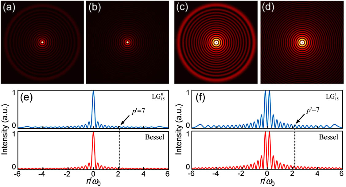
Fig. 1. Comparison of intensity distributions of higher-radial-order LG beams and their corresponding Bessel beams. (a), (b) l = 0 p = 15 l = 1 p = 15
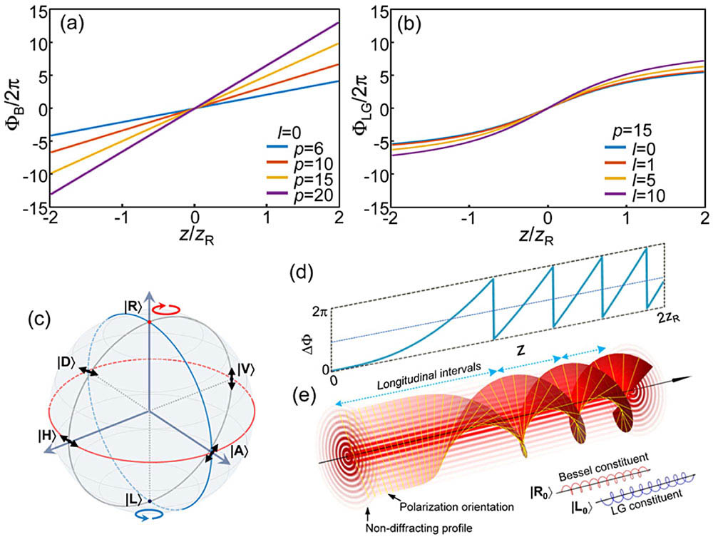
Fig. 2. (a), (b) Gouy phases of Bessel and LG beams with different transverse parameters, respectively. (c) Canonical Poincaré sphere. (d) Gouy phase difference between LG 15 0
Fig. 3. Experimental setup. HWP, half-wave plate; BS, beam splitter; PBS, polarized beam splitter; SLM, spatial light modulator; QWP, quarter-wave plate; L, lens; F, filter; M, mirror; P, polarizer. Insets: computer-generated holograms.
Fig. 4. Self-accelerated OA of a scalar (zeroth-order) quasi-non-diffracting beam. (a) 3D intensity profile of light field composed by an LG 15 0 z 0 z 1 z 2
Fig. 5. Self-accelerated OA of vector non-diffracting beams. (a) Higher-order Poincaré sphere composed by two kinds of quasi-non-diffracting components carrying OAMs. Insets: | R + 1 ⟩ | L + 1 ⟩ | H + 1 ⟩ | A + 1 ⟩ | V + 1 ⟩ | D + 1 ⟩ I x y – z z 1 z 2
Fig. 6. Self-accelerated OA of different vector quasi-non-diffracting beams. Backgrounds: intensity distributions of the vertical component; white lines and values denote the theoretical rotation angles.


Set citation alerts for the article
Please enter your email address

© Copyright 2018-2021 | Chinese Laser Press. All Rights Reserved 沪ICP备15018463号-20