
Cheng Zhang, Jin Yang, Wenkang Cao, Wei Yuan, Junchen Ke, Liuxi Yang, Qiang Cheng, Tiejun Cui, "Transparently curved metamaterial with broadband millimeter wave absorption," Photonics Res. 7, 478 (2019)
- Photonics Research
- Vol. 7, Issue 4, 478 (2019)
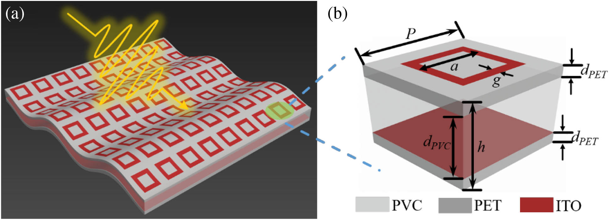
Fig. 1. (a) Schematic of the flexible and transparent MMA at millimeter frequencies. (b) Geometry of a unit cell.
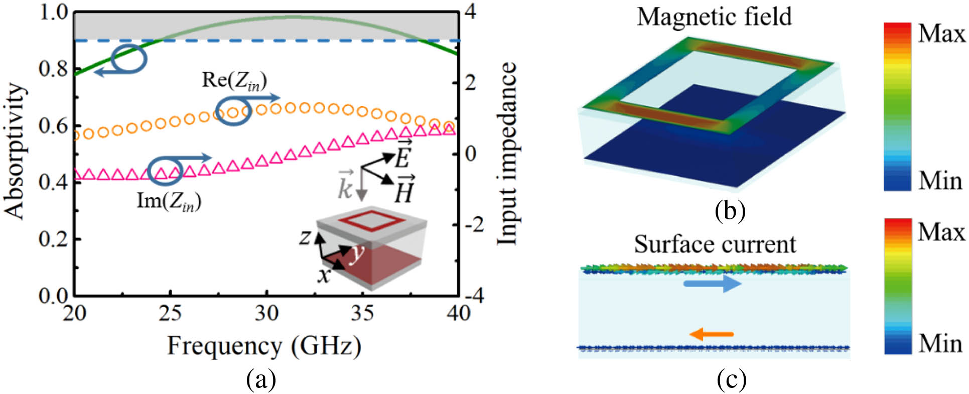
Fig. 2. (a) Simulated absorptivity spectra of the proposed MMA under normal incidence. (b), (c) Simulated magnetic field distribution and surface current distribution of the meta-atom at 32.0 GHz under normal incidence.
Fig. 3. (a) Schematic of the equivalent TL of the MMA. (b) TL model to retrieve the surface impedance of the ITO pattern. (c), (d) Calculated and simulated f r a g
Fig. 4. (a), (b) Schematic of the conformal MMA backed by a conducting cylindrical surface under normal incidence of TE and TM waves. (c)–(h) Scattering patterns on the x o z r = 75 r = 75
Fig. 5. Simulated angular stability of the MMA coating compared with the control conducting surface of the same size for (a) TE and (b) TM waves with r = 75 mm
Fig. 6. (a) Photograph of the fabricated sample, where the inset shows the measured light transmittance. (b) The whole experimental setup in a microwave chamber. (c), (d) Measured absorptivity spectra of the proposed MMA from 20.0 to 40.0 GHz at angles of 0°, 15°, 30°, and 45° for TE and TM waves. (e), (f) Measured RCS reduction of the MMA coating compared with the control conducting surface of the same size with r = 75 mm


Set citation alerts for the article
Please enter your email address

© Copyright 2018-2021 | Chinese Laser Press. All Rights Reserved 沪ICP备15018463号-20