
Lanting Li, Yuanlin Zheng, Haigang Liu, Xianfeng Chen. Reconstitution of optical orbital angular momentum through strongly scattering media via feedback-based wavefront shaping method[J]. Chinese Optics Letters, 2021, 19(10): 100101
- Chinese Optics Letters
- Vol. 19, Issue 10, 100101 (2021)
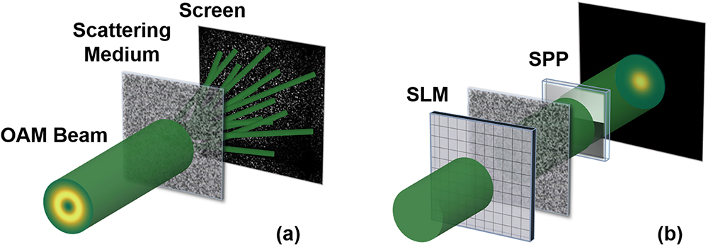
Fig. 1. Sketch map of optical OAM reconstitution through scattering media. (a) Without wavefront shaping, the OAM beam forms a disordered speckle pattern behind the scattering medium. (b) With an appropriate SLM phase mask applied in advance, optical OAM is reconstituted after scattering. Using an SPP with an opposite topological charge as a detection component, a focal point can be generated on the screen.
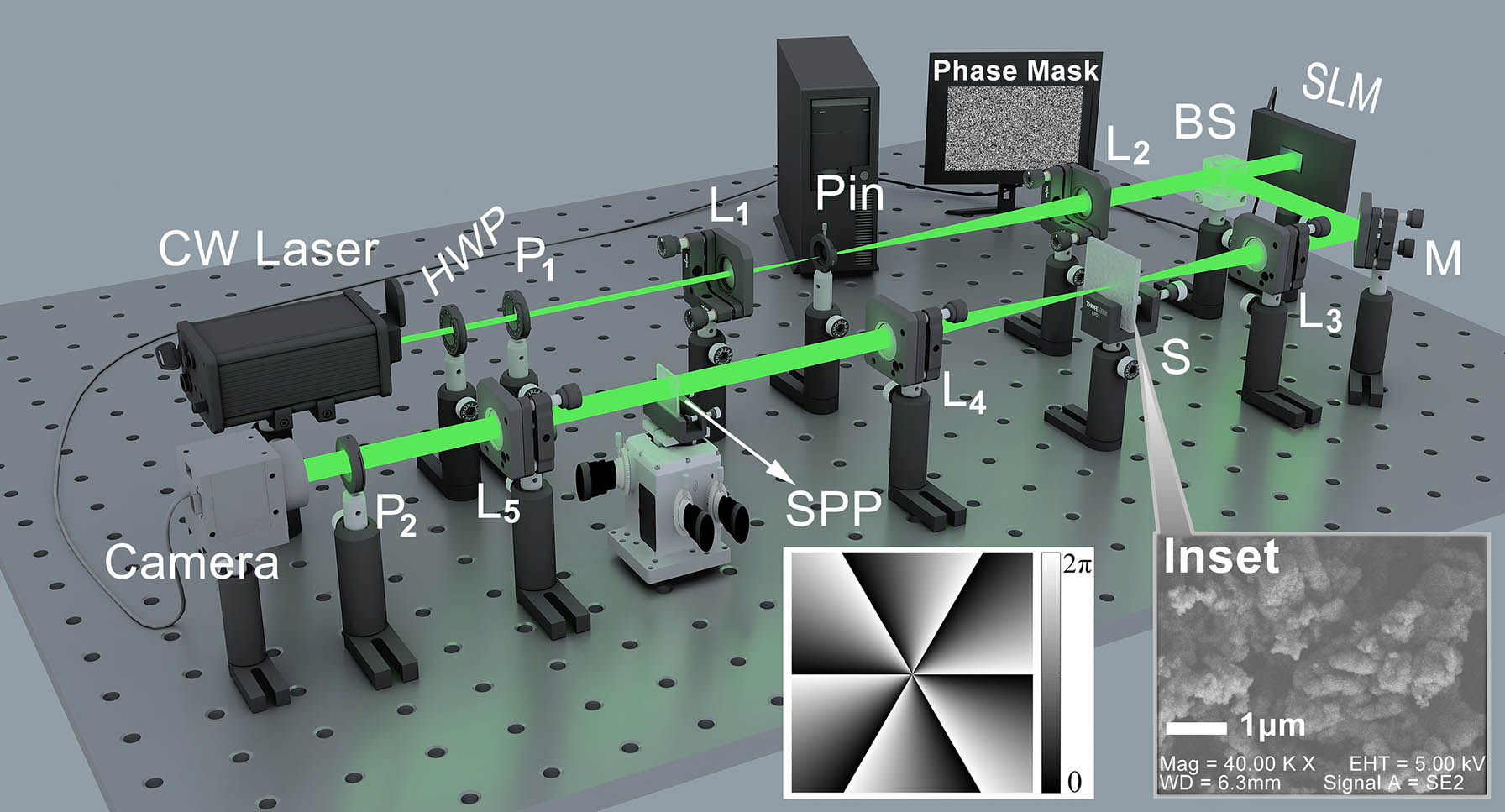
Fig. 2. Experimental setup for OAM restoration behind the strongly scattering media. HWP, half-wavelength plate;
Fig. 3. Experimental demonstration of measuring OAM and calibration. (a) An example for the OAM state with
Fig. 4. (a) Calibration of detecting system with an SPP of
Fig. 5. (a) Enhancement factor curves of different topological charges (ℓ = 4–7). In our experiment, a typical value is 150 after 500 generations. (b) Stability measurement of the focusing relative intensity over 10 h.
Fig. 6. Reconstitution of OAMs in different spatial directions. (a) and (b) have a deflection angle of around

Set citation alerts for the article
Please enter your email address
© Copyright 2018-2021 | Chinese Laser Press. All Rights Reserved 沪ICP备15018463号-20