
Su Wu, Chan Huang, Jing Lin, Tao Wang, Shanshan Zheng, Haisheng Feng, Lei Yu. Physics-constrained deep-inverse point spread function model: toward non-line-of-sight imaging reconstruction[J]. Advanced Photonics Nexus, 2024, 3(2): 026010
- Advanced Photonics Nexus
- Vol. 3, Issue 2, 026010 (2024)
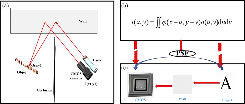
Fig. 1. The NLOS system and reconstruction principle. (a) A confocal NLOS imaging system with a CMOS camera to capture the image. (b) The imaging equation in an optical system with PSF and (c) propagation process from object to image in the NLOS system.
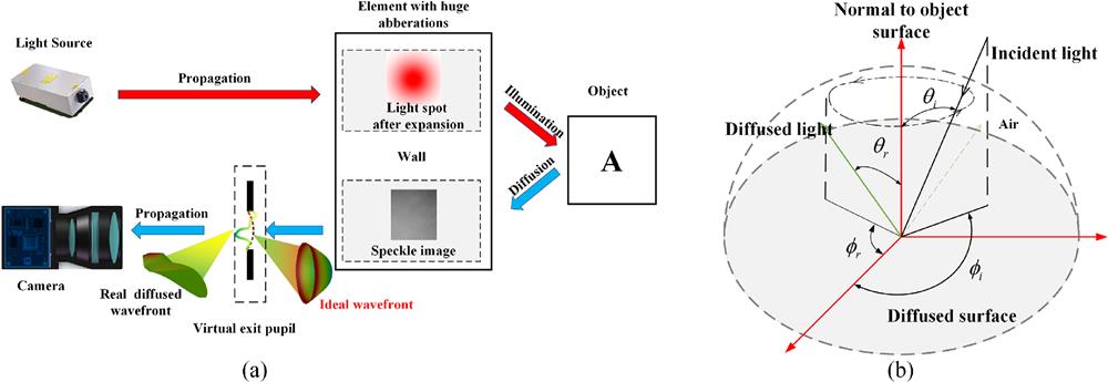
Fig. 2. Light path in the NLOS system. (a) Wavefront propagation process of diffuse reflection and (b) definition of diffuse reflection parameters.
Fig. 3. Flowchart of PCIN algorithm for NLOS imaging reconstruction. The speckle image captured by the camera is put into CNN, and PCIN iteratively updates the parameters in CNN using the loss function constructed by the speckle image and forward physical model. The optimized parameters are utilized to obtain a high-quality reconstructed image.
Fig. 4. Back and front of the experimental scene. Light passes from the laser, to the collimator, to the wall, to the hidden object, and finally to the camera.
Fig. 5. Comparison of the reconstructed images of various exposure time from the proposed PCIN method. (a) Speckle images of different exposure time captured by the camera. (b) Ground truth. (c) Reconstructed images of different exposure time.
Fig. 6. Comparison of the reconstructed images of various exposure time from the proposed PCIN method. (a) Speckle images of different exposure time captured by the camera. (b) Ground truth. (c) Reconstructed images of different exposure time.
Fig. 7. Comparison of the reconstructed cartoon images and Chinese characters of various exposure time from the proposed PCIN method. (a) Speckle images of different exposure time captured by the camera. (b) Ground truth. (c) Reconstructed images of different exposure time.
Fig. 8. Comparison of the reconstructed images of convex, concave, and wavy walls.
Fig. 9. Comparison of the reconstructed images of PR, CNN, and PCIN methods at 40 ms exposure time.
Fig. 10. Comparison of the reconstructed images of PR, CNN, and PCIN methods after a 10 deg change in image plane inclination.
Fig. 11. Comparison of the reconstructed images of PR, CNN, and PCIN methods at 20 ms exposure time.

Set citation alerts for the article
Please enter your email address
© Copyright 2018-2021 | Chinese Laser Press. All Rights Reserved 沪ICP备15018463号-20