• Acta Optica Sinica
  • Vol. 41, Issue 21, 2126001 (2021)
Xueyun Qin1、2, Liuhao Zhu1, Yuping Tai3, Jie Tang2, and Xinzhong Li1、2、*
Author Affiliations
  • 1School of Physics and Engineering, Henan University of Science and Technology, Luoyang, Henan 471023, China
  • 2State Key Laboratory of Transient Optics and Photonics, Xi′an Institute of Optics and Precision Mechanics, Chinese Academy of Sciences, Xi′an, Shaanxi 710119, China
  • 3School of Chemical Engineering and Pharmaceutics, Henan University of Science and Technology, Luoyang, Henan 471023, China
  • show less
    DOI: 10.3788/AOS202141.2126001 Cite this Article Set citation alerts
    Xueyun Qin, Liuhao Zhu, Yuping Tai, Jie Tang, Xinzhong Li. Properties of Optical Vortex Lattice Generated via Multiple Plane Wave Interference[J]. Acta Optica Sinica, 2021, 41(21): 2126001 Copy Citation Text show less
    Representation of wave vector coordinate and matrix. (a1)--(a3) Wave vector coordinate distribution patterns; (b1)--(b3) transferred wave vector coordinate distribution patterns. Bottom panel is its corresponding wave vector coordinate matrix representation
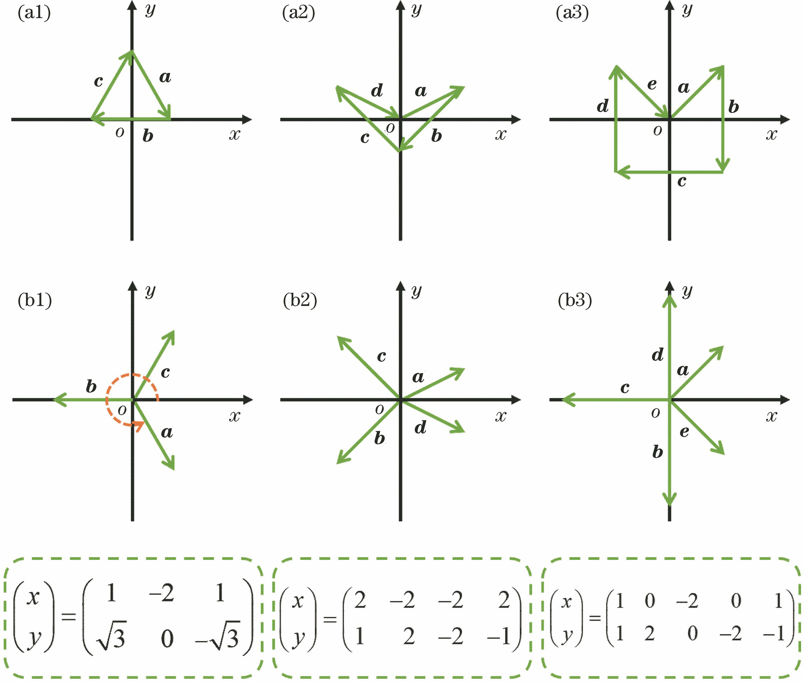
    Fig. 1. Representation of wave vector coordinate and matrix. (a1)--(a3) Wave vector coordinate distribution patterns; (b1)--(b3) transferred wave vector coordinate distribution patterns. Bottom panel is its corresponding wave vector coordinate matrix representation
    Light intensity, phase, and vortex point of OVL based on MPWI. (a1)--(a3) Intensity distribution patterns; (b1)--(b3) distribution patterns of phase and vortex point
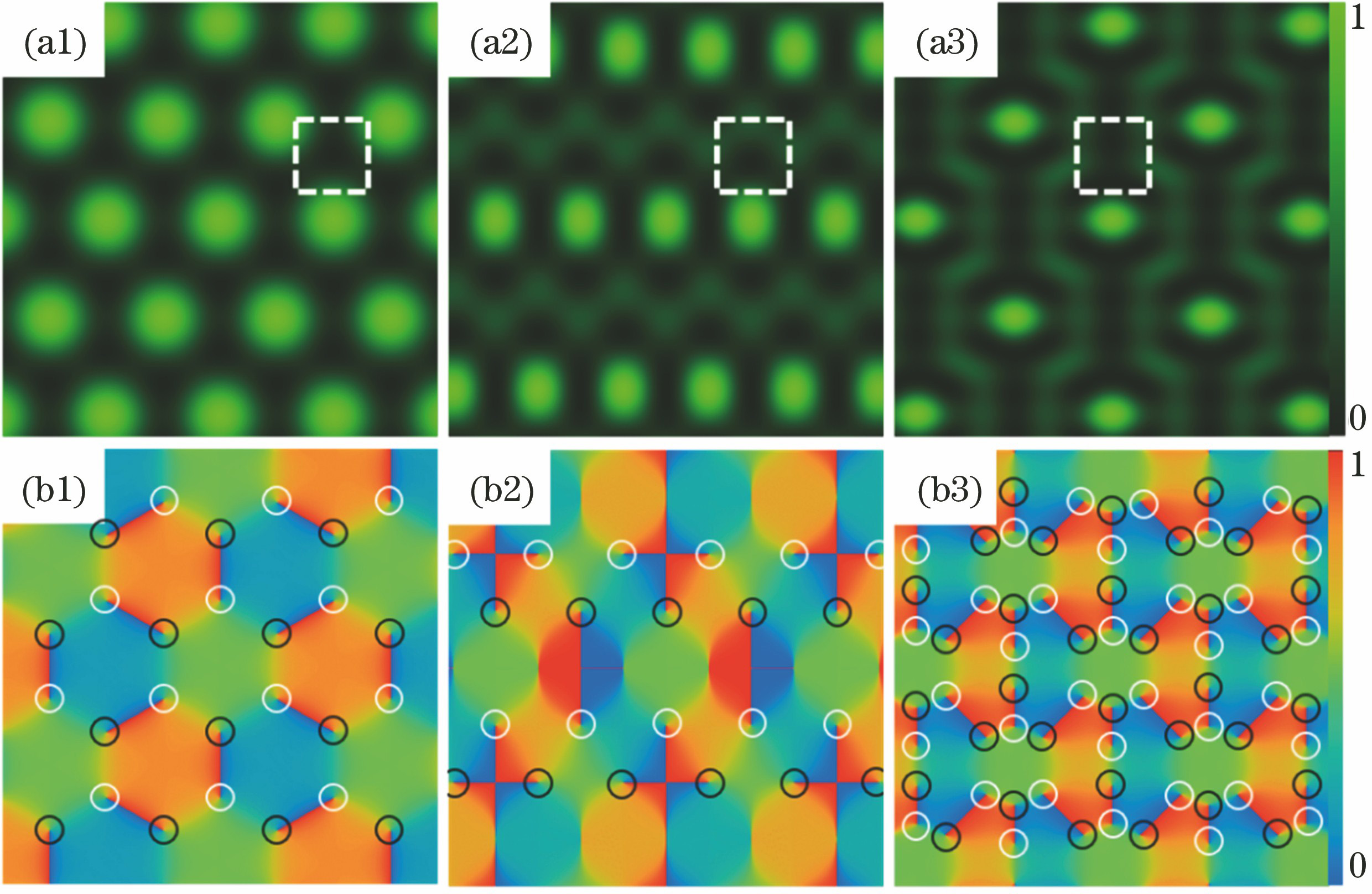
    Fig. 2. Light intensity, phase, and vortex point of OVL based on MPWI. (a1)--(a3) Intensity distribution patterns; (b1)--(b3) distribution patterns of phase and vortex point
    Four plane wave and five plane wave generate energy flow and gradient force in OVL . (a1)--(a4) Gradient force distribution patterns; (b1)--(b4) energy flow distribution patterns; (a2)--(b2) area between the two dash lines curves is Q1, and area outside the two dash lines is Q2; (a4)--(b4) area between the two left dash lines is Q1, and area between the right two dash lines is Q2
    Fig. 3. Four plane wave and five plane wave generate energy flow and gradient force in OVL . (a1)--(a4) Gradient force distribution patterns; (b1)--(b4) energy flow distribution patterns; (a2)--(b2) area between the two dash lines curves is Q1, and area outside the two dash lines is Q2; (a4)--(b4) area between the two left dash lines is Q1, and area between the right two dash lines is Q2
    Energy flow and gradient force as partial wave vectors are increased. (a1)--(a4) Wave vector coordinate distribution patterns; (b1)--(b4) gradient force distribution patterns; (c1)--(c4) energy flow distribution patterns, and longer-arrow lines are the movement tracks of the captured particles
    Fig. 4. Energy flow and gradient force as partial wave vectors are increased. (a1)--(a4) Wave vector coordinate distribution patterns; (b1)--(b4) gradient force distribution patterns; (c1)--(c4) energy flow distribution patterns, and longer-arrow lines are the movement tracks of the captured particles
    Energy flow and gradient force as the angles of the wave vector are simultaneously changed. (a1)--(a5) Wave vector coordinate distribution patterns; (b1)--(b5) gradient force distribution patterns; (c1)--(c5) energy flow distribution patterns, and longer-arrow lines are the movement tracks of the trapped particles
    Fig. 5. Energy flow and gradient force as the angles of the wave vector are simultaneously changed. (a1)--(a5) Wave vector coordinate distribution patterns; (b1)--(b5) gradient force distribution patterns; (c1)--(c5) energy flow distribution patterns, and longer-arrow lines are the movement tracks of the trapped particles
    Xueyun Qin, Liuhao Zhu, Yuping Tai, Jie Tang, Xinzhong Li. Properties of Optical Vortex Lattice Generated via Multiple Plane Wave Interference[J]. Acta Optica Sinica, 2021, 41(21): 2126001
    Download Citation