
Yizhou Tan, Ying Gu, "Characteristics of a Gaussian focus embedded within spiral patterns in common-path interferometry with phase apertures," Adv. Photon. Nexus 2, 036008 (2023)
- Advanced Photonics Nexus
- Vol. 2, Issue 3, 036008 (2023)
Abstract
Keywords
1 Introduction
Optical waves carrying orbital angular momentums (OAMs) have been applied in optical manipulation, microscopy, quantum optics, and information encoding1 since its first discovery by Allen et al. 30 years ago.2 To expand the controllability of optical vortices, efforts have been made to modify the doughnut-shaped intensity distribution of the vortex beams, such as using the interference of Laguerre–Gaussian (LG) beams in a Mach–Zehnder interferometer to rotate optically trapped particles,3 generating tiny dark spot diffraction of nonzero LG laser beams by an opaque disk,4 generating continuously adjustable vortex beams by coaxial or small-angle interference,5 using laser beams of different wavelengths incoherently overlaid to produce a subdiffraction dark spot,6 or generating concentric multirings by compound spiral phase plates.7
An important feature of the optical vortex beams is that the beam axis marks a singularity in the optical phase, and the amplitude of light becomes zero. Therefore, generating a bright Gaussian focus embedded with a spiral pattern remains challenging. Existing technology, such as computer-generated holograms, can generate a vortex beam of arbitrary patterns, including the diffraction–interference patterns studied in this work.8,9 However, optical elements have to be carefully aligned in the holographic off-axis optical system, which makes it infeasible in long-term optical trapping with high positioning accuracy. Meanwhile, although a metasurface plate allows conversion of a polarized input beam into an arbitrary vortex mode, it is not possible to modify the operating parameters dynamically in a prefabricated metasurface.10,11
The generalized phase contrast (GPC) method converts a pattern of phase modulation into the corresponding intensity distribution.12,13 Inspired by GPC, we propose a method for transforming an optical vortex field into the desired spiral interferograms. Amplitude aperture is referred to as the hole on an optically opaque screen, and its diameter determines the diameter of the bundle of rays traversing through. Different from a triangular amplitude aperture, which produces a triangular lattice correlated with the topological charge of the vortex beam in the far-field plane,14,15 we designed double-ring phase apertures to generate a concentric diffraction field. Based on the interference of the two diffraction fields, a sharp focus laser spot can be embedded into the middle of the spiral fringes.
Sign up for Advanced Photonics Nexus TOC. Get the latest issue of Advanced Photonics Nexus delivered right to you!Sign up now
Our experimental results have potential applications for micromanipulation: the measurements of torque, angle, and displacement of small objects such as enzymes link, protein binding, and DNA molecules require central trapping with rotation controls.11,16 Verification of quantum entanglement needs the petal-like fringes containing a brighter reference point for the rotation angle identification, and twisted light transmission at long distances will need a concentric brighter beacon laser inside the encoded vortex beams to resolve the atmospheric turbulence problems.17,18
2 Principle
In this work, the experimental principle includes three main issues: the design of the double-ring phase-aperture, the diffraction theory for phase element, and the coherent combination between the vortex beam and Gaussian beam.19
2.1 Phase Only Transform
The double-ring phase-aperture is made of a transparent element which is divided into two parts: the inner circle zone of radius
![]()
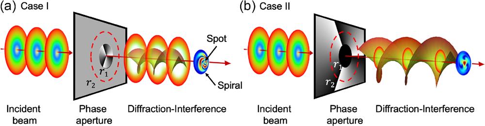
Figure 1.Interference between diffracted vortex beam and diffracted plane wave beam through a phase aperture in common-path interferometry. (a) Case I: the inner circle zone (
The double-ring phase-aperture is specially designed to realize three functions: (1) The element splits incident light at a designated ratio into two separate subbeams with phase difference. (2) The helical phase modulation profile, covered on the local zone, is able to generate a subbeam carrying OAM. (3) Diffraction patterns in the far-field are created by finite aperture diffraction. In the rest of this work, the double-ring phase-aperture element is frequently referred to as “phase aperture” for short.
The beam conversion process is shown in Fig. 1. In the far-field, the diffracted intensity distribution
2.2 Common-Path Interference Scheme
In our experiments, one zone of the double-ring phase-aperture element is covered with the helical phase modulated profile
When a plane wave beam passes through the double-ring phase apertures, the incident beam is split into high-order vortex beam
2.3 Interference between Two Diffraction Fields
The compound patterns, such as the Gaussian laser focus embedded with spiral petal-like fringes, are observed. We explain the physical reasons behind this result based on the theoretical model: (1) Both the vortex beam and the plane wave (or Gaussian laser) beam are converted into Fraunhofer diffraction fields through a finite aperture. (2) The coherent superposition of two diffraction fields generates interference fringes in the far-field.
A noticeable feature in our method is that a brighter Airy spot (Poisson spot) can automatically align with the center of the vortex beam all the time, which is attributed to the coherent combination of the vortex beam and the concentric Gaussian beam.
In this section, we analyze the theory and method for shaping the light optical wavefront by employing a transmissive spatial light modulator (SLM). The transmission-mode SLM is a necessary condition for realization of common-path interference in Fig. 1 and Fig. S1 in the Supplemental Material.
In following experimental study, we employ the reflection-mode SLM to demonstrate the diffraction-interference theory for vortex beams.
3 Experimental Setup
The experimental arrangement is shown in Fig. 2. The light beam from an He–Ne laser (
![]()
Figure 2.Experimental setup of common-path interferometry with a phase aperture.
4 Results
4.1 Beam Transformation through a Circular Phase Aperture in Common-Path Interferometry
To verify the feasibility of generating spiral petal-like fringes with a Gaussian focus in the middle, two experiments have been carried out. The experimental conditions correspond to Case I and Case II in Sec. 2.
In Experiment I, a transparent phase-aperture element is designed. The internal circle zone has an
![]()
Figure 3.(a) Circular phase-aperture element with a helical phase-modulated profile in the inner circle zone. (b) Numerically simulated light intensity distribution modulated by (a). (c) Experimentally recorded intensity distribution modulated by (a). (d) Circular phase-aperture element with a helical phase-modulated profile in the ring zone. (e) Numerically simulated light intensity distribution modulated by (d). (f) Experimentally recorded intensity distribution modulated by (d). The red dashed circle indicates the outer radius
The phase-modulated SLM produces a concentric beam in the Fresnel region: the inner is a vortex beam with a circular cross section, and the outer beam is a plane-wave beam with an annular cross section.
The interference between the diffraction fields of the vortex beam and the plane wave occurs in the far-field. Numerical calculations of the interference fringe are performed according to the theoretical model in Sec. 2 and Eqs. (A1)–(A4) in the Supplemental Material. The simulated intensity two-dimensional (2D)-distribution is shown in Fig. 3(b). A three-lobe spiral pattern with a brighter spot in the middle was observed in Fig. 3(c). The experimentally recorded interference fringe is in agreement with the numerical calculation result.
In Experiment II, a transparent phase-aperture element is designed. The internal circle zone has a uniform phase profile, and the ring zone has an
4.2 Beam Transformation through a Triangular Phase Aperture in Common-Path Interferometry
To verify the diffraction–interference effect of the triangular phase aperture, two experiments have been carried out.
In Experiment I, a transparent phase-aperture element is designed: the inner triangle zone has an
![]()
Figure 4.(a) Triangular phase-aperture element with a helical phase-modulated profile in the inner zone. The inner equilateral triangle has the side length
In Experiment II, a transparent phase-aperture element is designed: the inner circle zone has a uniform phase profile, and the zone between the inner triangle and the outer ring has an
In the Fresnel region, the inner plane-wave beam has a triangular cross section, and the outer beam is dark hollow vortex beam. Numerically simulated 2D distributions of the diffraction–interference pattern is shown in Fig. 4(e) and the experimentally recorded intensity distribution is shown in Fig. 4(f). A three-arm Y-shaped pattern with a brighter spot in the center of the interference fringe was observed.
4.3 Effect of Phase Aperture Size on the Diffraction–Interference Pattern
Next, we study the effect of the size of the phase aperture on the diffraction–interference pattern. The side length
![]()
Figure 5.(a), (d), (g), (j) Triangular phase-aperture element with a helical phase-modulated profile in the inner zone. The triangular phase aperture has a different side length,
The effect of the size of the circular and rectangular phase apertures on the diffraction–interference pattern is plotted in Fig. S2 in the Supplemental Material.
4.4 Rotating the Diffraction–Interference Pattern
The orientation of diffraction–interference pattern is turned by the following methods.
In the first experiment, the helically modulated phase profile stays constant. Meanwhile, the direction of the triangular phase aperture is rotated around the optical axis of the phase-aperture element, as shown in Figs. 6(a), 6(d), 6(g), and 6(j). The numerically simulated intensity 2D distribution and recorded intensity distribution demonstrated that the diffraction–interference pattern rotates in a clockwise direction. Results are shown in Fig. 6.
![]()
Figure 6.(a), (d), (g), (j) Triangular phase-aperture element with a helical phase-modulated profile inside. The orientation of the triangular phase aperture tilts with different angle
In the previous experiment, the phase shift in the outer zone of the phase aperture is set to
![]()
Figure 7.(a) Triangular phase-aperture element with a helical phase-modulated profile inside. The outer zone of the phase aperture has 0 phase shift. (b) Numerically simulated intensity distribution. (c) Experimental recording. (d) The outer zone of the phase aperture has
4.5 Effect of Phase Aperture Shape and Topological Charge on the Diffraction–Interference Pattern
The relationship between the shape of the phase aperture and the topological charge
![]()
Figure 8.(a), (b) Triangular phase aperture with a helical phase-modulated profile inside (
5 Discussion
5.1 Integration of Optical Trapping Function and Controllable Rotation Function
In optical Gaussian tweezers, a tightly focused Gaussian laser beam generates a trapping force that can capture and move small particles under a microscope.26,27 In an optical tweezers employed vortex beam, micrometer particles can be rotated by the twisting force originating from OAM.3,28,29
Owing to the different roles of optical Gaussian tweezers and optical vortex tweezers, each of them could not be replaced by another.3,30 To investigate and control rotational motion of small particles, it is necessary to develop a compact device that combines an optical trapping function with a controllable rotation function.30
We demonstrated that our experimental setup is able to generate three kinds of light intensity distributions: a tightly focused spot, a spiral petal-like fringe, and a doughnut-shaped fringe, which stay at the same center line. The phase-only transform method in our work supports a concept of optical tweezers that integrates the optical Gaussian tweezers and optical vortex tweezers in a single optical system.
By adjusting the inner size of the phase aperture, the light intensity distributions gradually evolve from a tightly focused spot to a doughnut-shaped fringe, as shown in Fig. 5 and Fig. S2 in the Supplemental Material. The experimental results are in good agreement with the theoretical calculation results.
For the side length of a triangular phase aperture
To achieve symmetric energy distribution with a bright center, a triangular phase aperture with even topological charges or a rectangular phase aperture with odd topological charges is necessary.14,15 When an even topological charges phase-modulated profile is loaded inside a triangular phase aperture, the interference fringe is asymmetric, and the central bright spot is either missing or weak, as shown in Figs. 8(a) and 8(b).33 While the circular phase aperture generates symmetric energy distribution in every lobe, it is difficult to distinguish the rotation, which will be discussed in the following section.
5.2 Rotate the Orientation of Diffraction–Interference Pattern by Adjusting the Phase Aperture
This work studies two strategies to rotate the orientation of diffraction–interference pattern. First, we explore the possibility of controlling rotation by turning the orientation of the triangular phase aperture. As shown in Fig. 6, the orientation of the triangular phase aperture is rotated by steps, with the orientation of the diffraction–interference pattern rotated accordingly.
The existing method rotates the orientation of the pattern by changing the optical path.3,16 By comparison, our approach realized concentric rotation of the diffraction–interference pattern of the optical vortex by adjusting the geometric variable only.3,16
Second, we show that the phase shift of a triangular phase aperture affects the orientation of the diffraction-interference pattern. By comparison, the phase shift of 0 [Figs. 4(b) and 4(c)] and
5.3 Potential Application in Optical Communication
To compensate for small perturbations in optical communication, a vortex beam carrying encoded OAM has been transformed into a
Long-distance twisted light transmission experiments have been realized, and the transmission quality of the OAM modes was primarily reduced due to atmospheric turbulence near the sender.17,18 The literature18 proposed employing a second laser beam to create a guide star.18 Our method is able to generate a Gaussian spot that can be used as the beacon laser with OAM-encoded information simultaneously in a simple optical setting.
5.4 Comparison between Optical Conversion Methods
Both computer-generated holograms and conventional MZIs are able to generate spiral petal-like patterns, which are similar to the patterns reported in this work.3,8,9,34 A holographic system is able to generate arbitrary patterns, but the zero-order diffracted beam is not used, which inevitably wastes incident optical power. Meanwhile, the holographic optical elements need to be carefully aligned due to the shortcomings of the off-axis optical system, making it unfeasible in long-time stable optical trapping.8,9
The MZI is the most common way to modulate intensity patterns of an optical vortex field. However, misalignment during interference may cause unsatisfactory interference fringes. And 50:50 splitting incident beam decreases its light conversion efficiency.3,20,21,34
In terms of fulfilling the special requirement, such as new concepts of optical tweezers and laser beacon in turbulent air (or as a reference point for OAM-coded pattern recognition), the common-path interferometer with a double ring phase aperture has advantages in various applications. For instance, it can work in a vibrating or noisy environment with relatively simple and compact optical setups. The transmissive phase-only element has high conversion efficiency. The double ring phase-aperture element produces concentric beams, which allow dynamical parameter adjustment of optical vortex fringes along the same axis; details are given in Sec. 4.36
6 Conclusion
This work proposes a phase-only method for transforming an optical vortex field into a desired spiral interference fringe. By employing double ring phase-aperture elements to realize common-path interference, a brighter spot is embedded with the optical vortex fringe. The embedded spot is located the singularity of the typical vortex beam is. In theory, this type of brighter spot originates from an Airy spot (or Poisson spot) due to the zeroth-order vortex beam diffracted at the phase aperture. A noticeable feature is that the brighter spot is automatically aligned with the central axis of the vortex beam because it is attributed to the coherent combination of vortex beam and concentric Gaussian beam. The theoretical calculated patterns are in excellent agreement with diffraction–interference fringes in experiment. Our experimental setup offers a method to implement optical tweezers that can trap and twist a particle (or biological sample) spatially and angularly. By controlling the phase shift and the size of the circular or polygonal phase aperture, the intensity distributions in the far field are able to evolve from a doughnut shape to a Gaussian focus, and the orientation of the diffraction–interference pattern can be rotated and controlled.
Yizhou Tan is an assistant researcher at Chinese PLA General Hospital. He received his BS and MS degrees from the National University of Defense Technology in 2011 and 2013, respectively, and his PhD in physics from Cavendish Laboratory, Cambridge University, in 2018. His current research focuses on laser medicine and its clinical application.
Ying Gu: Biography is not available.
References
[1] M. Padgett, R. Bowman. Tweezers with a twist. Nat. Photonics, 5, 343-348(2011).
[9] J. E. Curtis, D. G. Grier. Modulated optical vortices. Opt. Lett., 28, 872-874(2003).
[18] M. Krenn et al. Twisted light transmission over 143 km. Proc. Natl. Acad. Sci. U. S. A., 113, 13648-13653(2016).
[24] P. Fischer et al. The dark spots of Arago. Opt. Express, 15, 11860-11873(2007).
[30] F. Pedaci et al. Excitable particles in an optical torque wrench. Nat. Phys., 7, 259-264(2011).


Set citation alerts for the article
Please enter your email address

© Copyright 2018-2021 | Chinese Laser Press. All Rights Reserved 沪ICP备15018463号-20