• Opto-Electronic Advances
  • Vol. 4, Issue 3, 200021-1 (2021)
Lei Zhu1, Xuesong Zhao1, Chen Liu1, Songnian Fu2、*, Yuncai Wang2, and Yuwen Qin2
Author Affiliations
  • 1Wuhan National Laboratory for Optoelectronics, and School of Optical and Electronic Information, Huazhong University of Science and Technology, Wuhan 430074, China
  • 2School of Information Engineering, Guangdong University of Technology, and Guangdong Provincial Key Laboratory of Photonics Information Technology, Guangzhou 510006, China.
  • show less
    DOI: 10.29026/oea.2021.200021 Cite this Article
    Lei Zhu, Xuesong Zhao, Chen Liu, Songnian Fu, Yuncai Wang, Yuwen Qin. Flexible rotation of transverse optical field for 2D self-accelerating beams with a designated trajectory[J]. Opto-Electronic Advances, 2021, 4(3): 200021-1 Copy Citation Text show less
    Generation of 2D self-accelerating beam based on optical caustic and the rotation principle of transverse optical field for 2D self-accelerating beam. Two perpendicular components (a)−(b) of trajectory and light rays in default Cartesian coordinates. (c) The projection of multiplexed trajectory and the distribution of transverse optical field in default Cartesian coordinates; two perpendicular components (d)−(e) of trajectory and light rays in rotated Cartesian coordinates. (f) The projection of multiplexed trajectory and the rotated distribution of transverse optical field in rotated Cartesian coordinates.
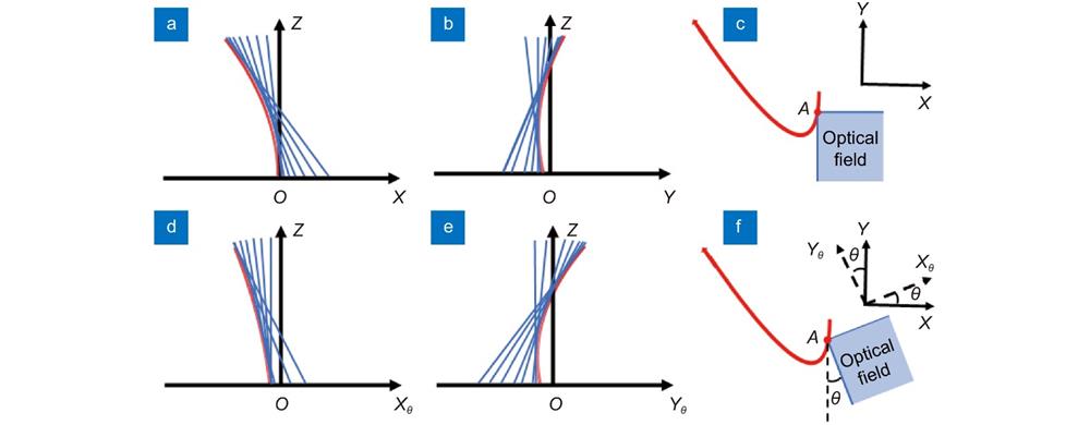
    Fig. 1. Generation of 2D self-accelerating beam based on optical caustic and the rotation principle of transverse optical field for 2D self-accelerating beam. Two perpendicular components (a)−(b) of trajectory and light rays in default Cartesian coordinates. (c) The projection of multiplexed trajectory and the distribution of transverse optical field in default Cartesian coordinates; two perpendicular components (d)−(e) of trajectory and light rays in rotated Cartesian coordinates. (f) The projection of multiplexed trajectory and the rotated distribution of transverse optical field in rotated Cartesian coordinates.
    Experimental setup for the optical field rotation of 2D self-accelerating beams. DFB: distributed feedback laser; Col.: collimator; PC: polarizer controller; P: polarizer; BS: beam splitter; SLM: spatial light modulator.
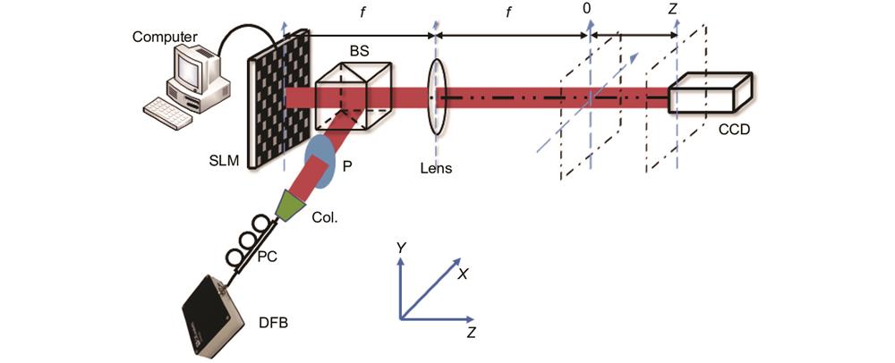
    Fig. 2. Experimental setup for the optical field rotation of 2D self-accelerating beams. DFB: distributed feedback laser; Col.: collimator; PC: polarizer controller; P: polarizer; BS: beam splitter; SLM: spatial light modulator.
    Different phase patterns and their calculated 3D optical distribution and trajectories. (a) Original phase pattern and its (b) 3D optical distribution and (c) the projection of trajectory. (d) Simply rotated phase pattern for -30° and corresponding (e) 3D optical distribution and (f) the projection of trajectory. (g), (j) Re-calculated phase patterns for -30° and 15°, and (h), (k) their 3D optical distribution and (i), (l) the projection of trajectory.
    Fig. 3. Different phase patterns and their calculated 3D optical distribution and trajectories. (a) Original phase pattern and its (b) 3D optical distribution and (c) the projection of trajectory. (d) Simply rotated phase pattern for -30° and corresponding (e) 3D optical distribution and (f) the projection of trajectory. (g), (j) Re-calculated phase patterns for -30° and 15°, and (h), (k) their 3D optical distribution and (i), (l) the projection of trajectory.
    Calculated and experimental results for the optical field rotation of 2D Airy beam at different propagation distances. (a− c) Calculated phase patterns. (d− f), (j− l), (p− r) Simulated and (g− i), (m− o), (s− u) experimental intensity profiles at distance of 0, 0.3 m and 0.6 m with a rotation angle of -30°, 0° and 15°, respectively.
    Fig. 4. Calculated and experimental results for the optical field rotation of 2D Airy beam at different propagation distances. (ac) Calculated phase patterns. (df), (jl), (pr) Simulated and (gi), (mo), (su) experimental intensity profiles at distance of 0, 0.3 m and 0.6 m with a rotation angle of -30°, 0° and 15°, respectively.
    Obstacle evasion experiment. (a) set-up; normalized received optical power with obstacle’s angle β of (b) -15° (c) 0° and (d) 30°. (blue solid curves are calculated results, and red dotted curves denote the experimental results.)
    Fig. 5. Obstacle evasion experiment. (a) set-up; normalized received optical power with obstacle’s angle β of (b) -15° (c) 0° and (d) 30°. (blue solid curves are calculated results, and red dotted curves denote the experimental results.)
    Lei Zhu, Xuesong Zhao, Chen Liu, Songnian Fu, Yuncai Wang, Yuwen Qin. Flexible rotation of transverse optical field for 2D self-accelerating beams with a designated trajectory[J]. Opto-Electronic Advances, 2021, 4(3): 200021-1
    Download Citation