• Infrared and Laser Engineering
  • Vol. 51, Issue 4, 20210549 (2022)
Xiaolei Li and Ming Gao
Author Affiliations
  • School of Ordnance Science and Technology, Xi'an Technological University, Xi'an 710021, China
  • show less
    DOI: 10.3788/IRLA20210549 Cite this Article
    Xiaolei Li, Ming Gao. Design of miniaturized dual-band observation system with composite aperture[J]. Infrared and Laser Engineering, 2022, 51(4): 20210549 Copy Citation Text show less
    Schematic diagram of sub-eye array
    Fig. 1. Schematic diagram of sub-eye array
    Schematic diagram of the relation between the angle between the adjacent sub-eye axes and the sub-eye field angle
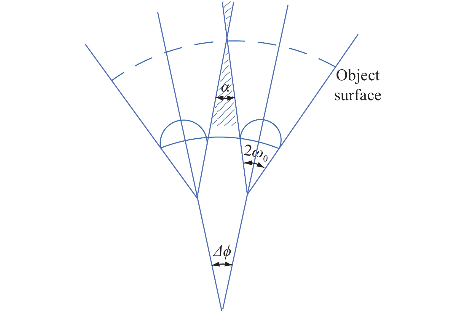
    Fig. 2. Schematic diagram of the relation between the angle between the adjacent sub-eye axes and the sub-eye field angle
    Schematic diagram of X-direction imaging principle
    Fig. 3. Schematic diagram of X-direction imaging principle
    Sub-eye structure light path diagram
    Fig. 4. Sub-eye structure light path diagram
    MTF of subocular system
    Fig. 5. MTF of subocular system
    RMS field of view of the sub-eye system
    Fig. 6. RMS field of view of the sub-eye system
    Field curve and distortion of sub-eye system
    Fig. 7. Field curve and distortion of sub-eye system
    Sub-eye lens array
    Fig. 8. Sub-eye lens array
    Structural light path diagram of receiving system
    Fig. 9. Structural light path diagram of receiving system
    MTF of the receiving system
    Fig. 10. MTF of the receiving system
    RMS field of view of the receiving system
    Fig. 11. RMS field of view of the receiving system
    Field curve and distortion of receiving system
    Fig. 12. Field curve and distortion of receiving system
    MTF in visible light band of sub-eye at −40 ℃ and +60 ℃
    Fig. 13. MTF in visible light band of sub-eye at −40 ℃ and +60 ℃
    MTF in mid-wave infrared band of sub-eye at −40 ℃ and +60 ℃
    Fig. 14. MTF in mid-wave infrared band of sub-eye at −40 ℃ and +60 ℃
    MTF in visible light band of receiving system at −40 ℃ and +60 ℃
    Fig. 15. MTF in visible light band of receiving system at −40 ℃ and +60 ℃
    MTF in mid-wave infrared band of receiving system at −40 ℃ and +60 ℃
    Fig. 16. MTF in mid-wave infrared band of receiving system at −40 ℃ and +60 ℃
    Tolerance analysis results of 500 groups
    Fig. 17. Tolerance analysis results of 500 groups
    NITD of each surface and total NITD of the medium wave infrared system
    Fig. 18. NITD of each surface and total NITD of the medium wave infrared system
    RelationshipConclusion
    Δϕ=0 The optical axes are parallel to each other, and the total field of view of the system is close to the size of the field of view of a single aperture
    0<Δϕ<ω0The outer two fields of view of the three adjacent subeyes meet at infinity, and the detection range of the middle sub-eye and the adjacent sub-eyes completely overlap
    Δϕ=2ω0The edge field of view of adjacent subapertures is parallel, there is a gap at infinity, and there is a blind spot in the field of view
    Δϕ>2ω0The peripheral fields of view of adjacent sub-eyes do not overlap, so there must be a blind spot
    Table 1. Relation between the angle between the adjacent subocular axes and the half-field angle of the sub-eye
    ParameterValue
    Field of view, FOV/(°)116
    Aperture of sub-eye, D/mm 10
    Angle of adjacent sub-eye, ∆θ/(°) 16
    Number of sub-eye37
    Radius of base layer, R/mm 65
    Table 2. Optical system parameters of bionic compound eye with curved surface
    ParameterVisibleMWIR
    Band/μm0.38-0.763-5
    Focal length/mm30
    F number 3
    Field angle/(°)20
    Table 3. Sub-visual parameters
    ParameterVisibleMWIR
    Band/μm0.38-0.763-5
    Field angle/(°)96
    F/# 2
    Pixel1456×1088640×512
    Pixel size/μm3.45×3.4515×15
    Table 4. Optical parameters of the receiving system
    Temperature/℃VIS/mmMWIR/mm
    −4029.979830.1276
    2029.998730.0417
    6030.017730.1470
    Table 5. Focal lengths of sub-eye systems in VIS and MWIR bands at different temperatures
    Temperature/℃Visible/mmMWIR/mm
    −402.60014.5925
    202.60544.672
    +602.61014.6130
    Table 6. Focal lengths of receiving systems in VIS and MWIR bands at different temperatures
    ParametersValum
    Radius/Fringes4
    Thickness/mm±0.01
    Surface decenter/mm±0.02
    Surface tilt/(°)±0.01
    Element decenter/mm±0.02
    Element tilt/(°)±0.01
    Index0.001
    Abbe0.5%
    Table 7. Tolerance allocation
    Xiaolei Li, Ming Gao. Design of miniaturized dual-band observation system with composite aperture[J]. Infrared and Laser Engineering, 2022, 51(4): 20210549
    Download Citation