1Key Laboratory of Optoelectronic Information and Sensing Technologies of Guangdong Higher Education Institutes, Guangdong Provincial Key Laboratory of Optical Fiber Sensing and Communications, Jinan University, Guangzhou 510632, China
2Department of Optoelectronic Engineering, Jinan University, Guangzhou 510632, China
3Department of Cell Biology, Yale University School of Medicine, New Haven, Connecticut 06510, USA
Opto-conveyors have attracted widespread interest in various fields because of their non-invasive and non-contact delivery of micro/nanoparticles. However, the flexible control of the delivery distance and the dynamic steering of the delivery direction, although very desirable in all-optical manipulation, have not yet been achieved by opto-conveyors. Here, using a simple and cost-effective scheme of an elliptically focused laser beam obliquely irradiated on a substrate, a direction-steerable and distance-controllable opto-conveyor for the targeting delivery of microparticles is implemented. Theoretically, in the proposed scheme of the opto-conveyor, the transverse and longitudinal resultant forces of the optical gradient force and the optical scattering force result in the transverse confinement and the longitudinal transportation of microparticles, respectively. In this study, it is experimentally shown that the proposed opto-conveyor is capable of realizing the targeting delivery for microparticles. Additionally, the delivery distance of microparticles can be flexibly and precisely controlled by simply adjusting the irradiation time. By simply rotating the cylindrical lens, the proposed opto-conveyor is capable of steering the delivery direction flexibly within a large range of azimuthal angles, from to 75°. This study also successfully demonstrated the real-time dynamic steering of the delivery direction from to 45° with the dynamical rotation of the cylindrical lens. Owing to its simplicity, flexibility, and controllability, the proposed method is capable of creating new opportunities in bioassays as well as in drug delivery.
1. INTRODUCTION
Optical tweezers, first developed by Arthur Ashkin [1], are capable of all-optically trapping particles, cells, biomolecules, and nanomaterials with an optical gradient force generated by a focused laser beam. Thanks to their novel capability to non-contact manipulate micro-/nano-objects, optical tweezers surpass traditional mechanical techniques, which require contact with the object and thus make it very difficult to manipulate fragile and easily damaged tiny particles [2]. So far, optical tweezers have been widely and successfully exploited in different fields ranging from physics to medicine to biology. Currently, various intriguing applications, such as manipulating micro/nanoparticles [3–11], cooling atoms [12,13], distinguishing cells [14,15], and probing the folding of a slipknotted protein [16,17], have been demonstrated successfully. In many applications, delivering or transporting tiny particles from an initial position to the targeted position is highly desirable. The use of piezoelectric devices, such as piezoelectric mirrors [18] and acousto-optic deflectors [19], could help optical tweezers to deliver multiple particles [18–21]; however, these devices have a high cost and mechanical complexity. Therefore, an opto-conveyor, which is capable of trapping a particle transversely in an optical beam, and meanwhile delivering the particle in a non-invasive and contamination-free way [22,23], provides an effective and simple method to extend the flexibility of optical manipulation. In this latter respect, controlling distance and steering direction in delivering micro/nanoparticles are desired features in the potential applications of opto-conveyors.
Recently, many attempts have been made to realize opto-conveyors using optical tractor beams [24–30], opto-thermoelectricity [31], and plasmonic tweezers [32–40]. The non-diffracting beams like Bessel beams and Airy beams have been reported as optical tractor beams to trap and deliver particles due to the features of propagation-invariance and self-healing ability [24–30]. Two or more coherent Bessel beams along the same axis can be formed to implement a one-sided delivery, and control the delivery distance by varying their relative phase [25]. However, their delivery directions are fixed. Various metallic structures, such as nanostructured arrays [32–35], slot waveguides [36], optical microcavities [37], and plasmonic disks [38–40], have been reported to improve plasmonic tweezers. However, these opto-conveyor candidates usually lack simplicity, flexibility, and continuity in the control of the delivery distance and direction, which in turn makes particle delivery difficult to direct. Generally, a plasmonic tweezer utilizes an optical potential well generated by metallic plasmonic resonances to trap particles. Sequentially activating the two adjacent traps on the local plasmonic resonances could realize the opto-conveyer function of delivering a particle from one trap to the adjacent trap [32–34]. Similarly, opto-thermoelectric tweezers have been reported to realize the opto-thermoelectric delivery of nano-objects using the metallic nanoantenna and light-induced gradient temperature field [31]. However, these plasmonic and opto-thermoelectric opto-conveyers both rely on the prior-fabricated metallic nanostructures on the substrate to determine the delivery direction [31–40]. Such prior-fabricated nanostructures suffer from sophisticated and high-cost fabrication, leading to unsteerable delivery direction. On the other hand, the discrete spatial distribution of the optical and opto-thermoelectric traps will lead to a discrete delivery distance, and thus such opto-conveyors cannot deliver the objects to an arbitrary targeted position. Additionally, for potential biological and medical applications, the synthetic nanostructures of the opto-conveyors lack biocompatibility and easily rupture in vivo tissue when delivering tiny objects, since they are made of semiconductor or metal materials.
In this paper, a direction-steerable and distance-controllable opto-conveyor is proposed and demonstrated for targeting the delivery of microparticles. The opto-conveyor is cost-effectively implemented with an elliptically focused laser beam obliquely irradiating on a glass substrate in a solution. Owing to its simple implementation with a small low numerical aperture () lens, the opto-conveyor exhibits several advantages, including low cost, easy switching direction, long delivery distance (μ), and flexible distance control, which together represent an efficient alternative tool for highly non-invasive and non-contact targeting delivery. Theoretical analyses reveal that light can generate a pico-Newton optical force in the proposed opto-conveyor for the transverse confinement and longitudinal transportation of the microparticle. Experimentally, the results show that the proposed opto-conveyor exhibits the capability of targeting the delivery of microparticles. In addition, the proposed scheme of the opto-conveyor allows for the flexible control of the delivery distance and the delivery period simply by adjusting the optical power and the irradiation time. Using the simple rotation of the cylindrical lens, the proposed opto-conveyor is capable of steering the delivery direction flexibly and dynamically. It is therefore experimentally concluded that the delivery direction is steerable within a large range of azimuthal angles, from to 75°. The continuous dynamical steering of the delivery direction within the range of the azimuthal angles from to 45° is also demonstrated. Therefore, owing to the advantages of the proposed opto-conveyor in terms of flexibility, controllability, and simplicity, this work can extend the potential applications of optical manipulation, e.g., biomedical assays and accurate drug delivery.
Sign up for Photonics Research TOC. Get the latest issue of Photonics Research delivered right to you!Sign up now
2. EXPERIMENTAL SETUP AND DELIVERY CONDITION
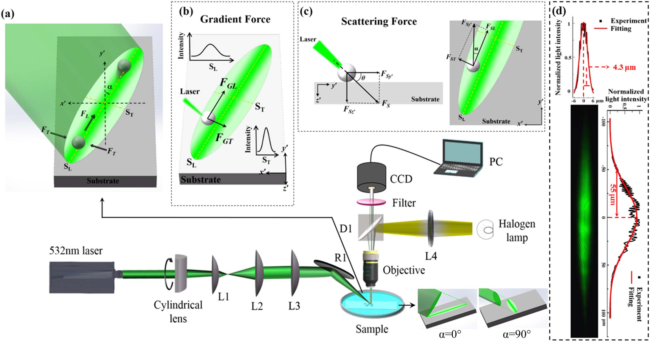
The experimental setup of the proposed opto-conveyor is schematically shown in Fig. 1(a) for delivering polystyrene (PS) microparticles in an aqueous solution. In the experiment, a 532 nm laser (CNI, MGL-F-532) is chosen to avoid high light absorption and the heat effect in the solution. The collimated laser beam is propagated along the direction and converted to an elliptical beam by a cylindrical lens. Then, the elliptical beam is expanded by convex lenses L1 and L2. Convex lens L3 with a low NA () focuses the elliptical beam and provides the capability of the long-distance control of microparticle delivery. The focused beam is reflected by a mirror, R1, and obliquely irradiated on the surface of the substrate to generate a micro-sized elliptical opto-conveyor. The incident angle between the reflected light and the direction is defined as . A microscope (Nikon ECLIPSE LV100ND), an objective (Nikon, 10×, ), a CCD camera (Mshot, MC21-N), and a filter of 532 nm are connected to clearly observe and record the transport characteristics of microparticles. The 3.5 μm radius PS microspheres used in the experiments are from Dae Company. For the opto-conveyor, a coordinate system with , , and axes is established in which the direction is the propagation direction of the laser beam before being reflected by the mirror R1. In the elliptical opto-conveyor, the direction of the long axis is defined as the longitudinal direction, and the direction of the short axis is defined as the transverse direction. Noticeably, when the cylindrical lens is rotated, the longitudinal direction of the opto-conveyor rotates accordingly. Therefore, the angle between the longitudinal direction and the direction is denoted as the azimuthal angle . The schematic diagrams of the opto-conveyors are shown by the insets in Fig. 1(a) for the azimuthal angles of 0° and 90°.
Figure 1.Schematic diagrams of (a) the experimental setup and the opto-conveyor. R1, reflection mirror 1; L1, L2, L3, and L4, lenses. and denote the long and short axes of the opto-conveyor. and represent the driving and confining forces acting on the microparticle. The azimuthal angle denotes the angle between the longitudinal direction and the direction. The two insets show the schematic diagrams of the opto-conveyor for azimuthal angles of 0° and 90°, respectively. (b) The optical gradient force and (c) the optical scattering force () acting on the microsphere, respectively. and denote the longitudinal and transverse components of the optical gradient forces, respectively. and denote the components of the optical scattering forces along the and directions. and are the transverse and longitudinal components of , respectively. (d) The measured elliptical spot of the opto-conveyors on the substrate. The Gaussian waists along long and short axes are estimated as 55 μm and 4.3 μm, respectively.
Because the opto-conveyor is generated by reflecting an elliptical Gaussian beam obliquely onto a substrate, the intensity distributions along the transverse and longitudinal directions are both in Gaussian shapes but with different waists. Figure 1(d) gives the experimentally measured intensity distribution of the opto-conveyor. During the measurement, a diffuse substrate is used. The intensity distributions along transverse and longitudinal directions are fitted by Gaussian functions, respectively. The waist radii of the Gaussian profiles are estimated at the position of the of the maximum light intensity, which are 4.3 μm and 55 μm, respectively. Thus, based on the ray optics, the irradiated microsphere is acted by the transverse and longitudinal components of the optical gradient forces, termed and , as shown in Fig. 1(b). In addition, due to the change of the light momentum caused by reflection and refraction, an optical scattering force is exerted on the microparticle, i.e., , as shown in Fig. 1(c). Moreover, the direction of the optical scattering force is consistent with the direction of the obliquely incident light. Due to the existence of the substrate, the optical scattering force can be divided into the components and along the and directions. Obviously, the scattering force will push the microparticles against the substrate, which can reduce the influence of buoyancy. Furthermore, the component of the scattering force can be divided into the transverse and longitudinal components as and , respectively. Therefore, the corresponding transverse and longitudinal resultant forces of the optical gradient force and the optical scattering force acting on a microparticle in the opto-conveyor, named as the driving force and the confining force in Fig. 1(a), can be calculated as follows: The incident and azimuthal angles can be tuned independently by adjusting mirror R1 and rotating cylindrical lens, respectively. Throughout the paper, the incident angle is fixed to be 30° for both experimental investigation and theoretical calculations unless otherwise specified. The azimuthal angle is tuned to control the delivery direction. When aiming at the delivery condition of the proposed opto-conveyor, the driving force must remain along one direction without considering the drag force.
3. THEORY OF THE OPTO-CONVEYOR
Since the collimated Gaussian laser beam at a wavelength is focused by a low NA () convex lens and reflected by a mirror, the laser beam propagates along the axis and is focused into an elliptical beam waist in the focus plane in theory, as shown in Fig. 2(a). Therefore, in the beam waist, the Gaussian beam can be regarded as two independent beams, named the – beam and the – beam, respectively [41], and its complex electric intensity can be expressed as follows [5]: where denotes the wavenumber, and is the refractive index of the background water. Meanwhile, denotes the radius of the beam, which is given by and for the – beam and – beam, respectively. Their radii of curvature of the very nearly spherical wavefronts can be expressed as and , with and denoting the focus positions of the – beam and the – beam, respectively. Meanwhile, and represent the waist radii of the – beam and the – beam, respectively.
Figure 2.(a) Formation of the opto-conveyor on the substrate. The distributions of the electric intensity in (b) , (c) , and (d) planes, respectively. The dimensionless optical force (DOF) of a microsphere with a radius μ when it moves along the (e) , (f) , and (g) axes, respectively. , , and are the relative positions of the microsphere along the , , and axes.
The waist radii of the Gaussian beam along the and axes are set to be 4.3 μm and 55 μm according to the experimental measurement in Fig. 1(d). According to Eq. (3), the intensity distributions in the , , and planes can be calculated, and the results are shown, respectively, in Figs. 2(b)–2(d) with . Due to the diameter of the microparticles (μ) being much larger than the optical wavelength (0.532 μm) in the experiments, a dimensionless optical force (DOF), , is defined, where is the resultant optical force, is the optical power injected into the opto-conveyor, and is the propagation speed of light through the background medium. The DOF is proportional to the optical force per unit power acting on a microsphere [41,42]. Therefore, the DOFs of a PS microsphere with a radius μ along the , , and axes can be calculated, and the numerical results are shown in Figs. 2(e)–2(g), respectively. , , and are the relative positions of the microsphere: , , and . As shown in Fig. 2(e), is always zero along the axis, because the positive and negative optical gradient forces in the direction are counteracted. However, an optical scattering force in the and directions still can act on the microsphere, and thus and are not zero. Similarly, in Fig. 2(f), for the microparticle on the axis, and are not zero, but remains zero. Remarkably, is always positive, and is much higher than . Figure 2(g) shows that is positive as the optical scattering force and the optical gradient force have the same direction when μ, yet becomes negative at μ because the gradient and scattering forces act in opposite directions. Remarkably, although the obliquely incident light is not focused on the substrate, the distribution of the light intensity of the opto-conveyor is nearly identical to that of the beam waist. Therefore, the opto-conveyor on the substrate can be approximated as the beam waist of the obliquely incident laser beam, and the optical gradient force and the optical scattering force acting on the microparticle in the opto-conveyor can be considered as the same as those in the beam waist.
Based on Figs. 2(b)–2(d), we calculate the gradient and scattering forces. According to Eqs. (1) and (2), at the optical power of 484.1 mW used in the experiments, the driving force and the confining force acting on a 3.5 μm radius microparticle in the opto-conveyor are calculated at different azimuthal angles (, 45°, and 90°), respectively, as exhibited in Fig. 3. It can be seen from Figs. 3(a)–3(c) that at different azimuthal angles, the microparticle will be actuated to the equilibrium point of the confining force. With the increase of the azimuthal angle, the equilibrium point shifts positively, i.e., away from the long axis of the opto-conveyor. This is because according to Eq. (2), the transverse component of the optical scattering force plays a role in the confinement of a microsphere when the azimuthal angle is not 0° and generates an asymmetric resultant force since the transverse component of the optical gradient force is symmetrical, as shown in Fig. 2(e). According to Ref. [43], in addition, the mean value of the Brownian force is . For a 3.5 μm radius microparticle at 300 K temperature, the Brownian force is estimated as 0.002 pN, which is 4 orders smaller than the confining forces, and thus the microparticle can be well confined in the opto-conveyors.
Figure 3.Confining forces () for the azimuthal angles of (a) 0°, (b) 45°, and (c) 90°, respectively. The red dotted lines show the equilibrium points of the confining force. Driving forces () for the azimuthal angles of (d) 0°, (e) 45°, and (f) 90°, respectively. The black dotted lines show the positions of the maximum driving force for the azimuthal angles of 0° and 45°, and the equilibrium point of the positive and negative driving force for the azimuthal angle of 90°, respectively. and are the relative positions of the microsphere along the short and long axes of the opto-conveyor, respectively.
Furthermore, Figs. 3(d)–3(f) show that the maximum value of the driving force exerted on the microsphere is inversely proportional to the azimuthal angle. When the azimuthal angles are 0° and 45°, due to the positive driving force on the pico-Newton level, the irradiated microparticles will be transported longitudinally. In addition, according to the distribution of the driving force, the movement of the microparticle will undergo an acceleration stage and a deceleration stage in order. Remarkably, the position of the maximum driving force has a negative shift, for a reason similar to that of the position of the confining force. For the microsphere, this will result in the time consumption of the deceleration process being longer than that of the acceleration process. However, when the azimuthal angle is enhanced to 90°, as shown in Fig. 3(f), the driving force significantly lowers. Noticeably, according to Eq. (1), it can be concluded that the driving force at the negative azimuthal angle has the same distribution as that at the positive azimuthal angle. Overall, the proposed opto-conveyor can provide the transverse confinement and longitudinal delivery of a microparticle, except when the azimuthal angle is 90°.
4. EXPERIMENTAL RESULTS AND DISCUSSION
A. Targeting Delivery
The delivery process of a 3.5 μm radius PS microsphere at the incident optical power of 400 mW, the azimuthal angle of 0°, and the incident angle of 30° is shown in Visualization 1 in the supporting information (SI). It can be seen that the irradiated microparticle can be stably transported along the longitudinal direction and stopped smoothly at the edge of the opto-conveyor. The whole delivery distance is about 240 μm, and the time consumption is about 22 s. Therefore, the proposed opto-conveyor can easily implement the delivery of the PS microparticle.
Figure 4 shows the delivery processes of the irradiated PS microparticles at six different positions in the proposed opto-conveyor (see Visualization 2 in SI). This figure shows that when the start points of the microspheres are on the long axis, they are transported directly along the longitudinal direction. But due to the higher confining force, the microparticles at other positions are obviously trapped transversely, and they are simultaneously transported along the longitudinal direction as well. These results are in accordance with the theoretical analysis of the opto-conveyor model. Moreover, during these delivery processes, all the terminals are in a deviation range of 10 μm. This may be caused by the measurement deviation of the opto-conveyor and the flow of the aqueous solution. Therefore, the proposed opto-conveyor can realize the targeting delivery of the irradiated PS microparticle at an arbitrary start point.
Figure 4.(a) Targeting delivery processes and (b) the delivery trajectories of the PS microparticles at six different start points. The yellow dotted lines show the trajectories of microparticle movement. The green ellipses denote the opto-conveyor, and the reddish dots denote the positions of the microparticles every second.
Figure 5 shows the delivery processes of the microparticles for five different incident optical powers of 221.7 mW, 337.6 mW, 484.1 mW, 702.5 mW, and 769.4 mW, respectively, with a 1 s interval time between two adjacent microparticles (see Visualization 3 in SI). It can be seen that the delivery terminals are all within a deviation range of 10 μm, which is consistent with the result in Fig. 4. Therefore, for the proposed opto-conveyor, the optical power does not affect its capacity for targeting delivery. Figures 6(a) and 6(b) show the speed distributions as functions of time and position during the delivery processes, respectively. The particle speed is extracted from videos at 2 frames per second. These distributions demonstrate that with the increase of the optical power, the time consumption of microparticle delivery decreases from 30 s to 13 s. In addition, each microsphere is rapidly accelerated to the maximum speed, and then gradually decelerated until it reaches the terminals. In Fig. 6(a), through Gaussian profile, it can clearly be seen that the time consumption of the deceleration process is longer than that of the acceleration process, which is in agreement with the theoretical movement state.
Figure 5.Delivery processes of the microspheres for five different optical powers of 221.7 mW, 337.6 mW, 484.1 mW, 702.5 mW, and 769.4 mW, respectively. The incident angle is 30°, and the azimuthal angle is 0°. The yellow dotted lines show the trajectories of microparticle movement, and the reddish dots denote the positions of the microparticles every second.
Figure 6.Speed distributions during microparticle delivery processes as functions of (a) time and (b) position for five different optical powers of 221.7 mW, 337.6 mW, 484.1 mW, 702.5 mW, and 769.4 mW in the experiments, respectively. (c) The theoretical and experimental distributions of the transport speed and driving force at the optical power of 337.6 mW. (d) The experimental and theoretical maximum speed and the delivery time consumption versus the optical power, respectively.
Considering the background medium of water, the theoretical distribution of the transport speed can usually be calculated by Langevin’s equation as [44] where is the mass of the particle, and is the transport speed along the long axis of the opto-conveyor. denotes the drag force on the microsphere, and can be calculated by Stokes law as where is the radius of the microparticle, and the viscosity coefficient of water is . However, in the current experiments, because the microsphere is transported in the proposed opto-conveyor on the surface of the substrate in the water, the viscosity coefficient became larger. Thus, the viscosity coefficient needs to be corrected as [45] where is the distance between the center of the sphere and the substrate, which is equal to the radius of the particle. The correction viscosity coefficient of water is . As a result, the corrected Langevin’s equation for the calculation of the transport speed in the experiments is as follows:
Therefore, the theoretical distribution of the transport speed at the optical power of 337.6 mW is calculated and shown in Fig. 6(c). It can be seen that although the experimental data are slightly lower than the theoretical results, except with regard to the top speed, the tendencies of their distributions are essentially consistent. This may be because the optical forces are approximate, the substrate is not smooth enough, or the water flows with the movement of the microparticles. In addition, according to the measured experimental speed, the experimental driving force is calculated by Eq. (7). Figure 6(c) also shows that the experimental distribution of the driving force is consistent with the theoretical distribution. Similarly, in Fig. 6(d), the experimental time consumption of the microsphere delivery also has a similar tendency to that of the theoretical results. Furthermore, through fitting the experimental data between the optical power and the maximum speed, as shown in Fig. 6(d), the relationship is linear with a high linear correlation coefficient of 99.1%. Thus, it can be calculated that the threshold of the optical power for transporting the 3.5 μm radius PS microsphere is about 37.83 mW. Therefore, for the proposed opto-conveyor, these results confirm the validity of microparticle delivery using optical force and the correctness of the theoretical model. In addition, based on the ray optics, optical forces for particles with a radius larger than 1 μm are calculated. For μ, the confining force is much larger than the Brownian force. Although the driving force decreases with the radius, the Stokes force and the particle mass also decrease, which ensures the effective optical driving movement for a 1 μm radius particle.
C. Control of the Delivery Distance
Ideally, extracting the results of the transport characteristics in Fig. 6 allows for the further control of the delivery distance of microparticles flexibly and precisely. Figure 7(a) shows the theoretical relationship between the irradiation time, the optical power, and the delivery distance. When the optical power is set at 484.1 mW, as shown in Fig. 7(b), the delivery distances of 58 μm, 136 μm, 158 μm, and 210 μm at the irradiation times of 4 s, 5 s, 6 s, and 22 s, respectively, can be controlled. Furthermore, another experiment is conducted at the same conditions, and the results are shown in Fig. 8 (see Visualization 4 in SI).
Figure 7.(a) Relationship between the irradiation time, optical power, and the delivery distance, and (b) relationship between the irradiation time and the delivery distance at the optical power of 484.1 mW. The dotted lines show the delivery distance at the irradiation times of 4 s, 5 s, 6 s, and 22 s, respectively.
Figure 8.Delivery distances of microparticles at the optical power of 484.1 mW with the delivery periods of 4 s, 5 s, 6 s, and 26 s, respectively. The incident angle is 30°, and the azimuthal angle is 0°.
As Fig. 8 shows, by turning off the laser after the delivery periods of 4 s, 5 s, 6 s, and 26 s, it can be seen that the microparticles all stop immediately, and that their delivery distances are 58 μm, 134 μm, 152 μm, and 211 μm, respectively. According to the comparison of the theoretical and the experimental results of the delivery distance in Table 1, it can be seen that the experimental results of the delivery distances are basically in agreement with the theoretical relationship in Fig. 7(b), and they are also repeatable within the acceptable deviation range. Consequently, by simply adjusting the optical power and the irradiation time irradiated into the opto-conveyor, the delivery distance and the delivery period of a microparticle can be controlled flexibly and precisely. In a particular situation, the proposed opto-conveyor can not only realize the targeting delivery for drug particles but can also ensure their timeliness, if necessary.
Delivery Distance
Period (s)
Theory (μm)
Experiment (μm)
Deviation (%)
4
58
58
0
5
136
134
1.47
6
158
152
3.80
22
210
211
0.48
Table 1. Theoretical and Experimental Results on the Control of the Delivery Distance
The steering of the delivery direction enables the microparticles to be transported flexibly and dynamically to the targeting positions. In theory, the proposed opto-conveyor can easily adjust the delivery direction of microparticles by simply rotating the cylindrical lens instead of changing the structure of the opto-conveyor. In the experiments, the delivery processes of microparticles for the azimuthal angles of 18°, 32°, 45°, 60°, 75°, and 90° at the optical power of 484.1 mW and the incident angle of 45° are further investigated. The delivery trajectories are shown in Fig. 9 (see Visualization 5 in SI). It can be seen in Fig. 9(a) that except in the case when the azimuthal angle is 90°, the microspheres are all transported longitudinally to other edges of the opto-conveyor, and that their delivery processes and characteristics are similar to the results in Fig. 6. For the case of the azimuthal angle being 90°, microparticles are confined on the long axis of the opto-conveyor without delivery process. This is because the driving force for this case results from the gradient force, which is about 7 times smaller than the scattering force, and thus cannot deliver microparticles. The delivery distance and maximum speed changing with the azimuthal angle are extracted from Fig. 9(a), and compared with the theoretical maximum delivery distance and the theoretical maximum speed, respectively. The theoretical maximum delivery distance is equal to the long axis of the opto-conveyor, which decreases with the azimuthal angle . The maximum speed is calculated according to Eq. (7). As shown by Figs. 9(b) and 9(c), the theoretical and experimental results are in good agreement, excepting for the point of in Fig. 9(b). This is because this particle does not start at one end of the opto-conveyor (elliptical spot) as shown by the lower left image in Fig. 9(a). The theoretical maximum delivery distance can be increased easily by enlarging the incident angle. In addition, according to Eq. (1), the delivery of a microparticle at the negative azimuthal angle is the same as that at the positive azimuthal angle. Hence, it can be concluded that the proposed opto-conveyor is capable of flexibly steering the delivery direction within a large range of azimuthal angles from to 75°, by simply rotating the cylindrical lens. Additionally, in Visualization 6 in SI, the implementation and demonstration of the continuously dynamical steering of the delivery direction within the range of the azimuthal angles from to 45° are provided. Therefore, the simple rotation of the cylindrical lens enables steering of the delivery direction of microparticles continuously and dynamically for a large range of azimuthal angles.
Figure 9.(a) Delivery trajectories for different azimuthal angles at the optical power of 484.1 mW and the incident angle of 45°. The optical images of the opto-conveyors are shown in each inset. (b) The experimental and theoretical delivery distances, and (c) the experimental and theoretical maximum speeds of the microparticles versus azimuthal angles.
E. Simultaneous Delivery of Microparticles to a Target Object
The simultaneous delivery of PS microparticles at different start points to a targeting sphere at the optical power of 484.1 mW is shown in Fig. 10 (see Visualization 7 in SI). It can be seen that the irradiated PS microparticles are all delivered accurately to the targeting sphere in 13 s. Despite the first microsphere gradually leaving the surface of the targeting object due to the extrusion of the following ones, the others ultimately adhere to the targeting matter. Therefore, in practical applications, the proposed opto-conveyor may help to deliver drug particles accurately and flexibly and can additionally enhance their arrival probability to diseased tissues effectively.
Figure 10.Simultaneous delivery of microparticles to a targeting object at the optical power of 484.1 mW, the incident angle of 30°, and the azimuthal angle of 0°. The dotted lines denote the opto-conveyor.
In conclusion, a direction-steerable and distance-controllable opto-conveyor is demonstrated with an elliptically focused laser beam obliquely irradiating on a glass substrate for non-invasive and non-contact targeting delivery of microparticles in a solution. Theoretically, using the transverse and longitudinal resultant forces of the optical gradient force and the optical scattering force, the transverse confinement and the longitudinal transportation of microparticles can be realized respectively. Thanks to its simple implementation with a small low NA () lens, the proposed opto-conveyor is capable of achieving a two-dimensional long-distance delivery (μ) cost-effectively. The experimental results show that the proposed opto-conveyor enables microparticles to achieve targeting delivery. In addition, the proposed scheme of the opto-conveyor allows for the control of the delivery distance and the delivery period flexibly and precisely by simply adjusting the irradiation time. With a simple rotation of the cylindrical lens, the delivery direction is steerable flexibly and dynamically. It is experimentally shown that the proposed opto-conveyor is capable of steering the delivery direction flexibly within a large range of azimuthal angles from to 75°. The real-time steering of the delivery direction from to 45° with the continuously dynamical rotation of the cylindrical lens is also demonstrated. Benefiting from the simple, flexible, and controllable delivery of microparticles, the proposed method has potential applications in biological and medical sciences, such as the delivery of targeted drugs, biomedical assays, and the distinction of cells.
Acknowledgment
Acknowledgment. The authors would like to thank Prof. Yongli Zhang for his inspiring discussion.
APPENDIX A: METHODS
Details of the Experimental Setup. In the experimental setup in Fig.?1, the 532?nm Gaussian laser beam diameter is about 2?mm. The cylindrical lens with a focal length of 20?cm can focus the laser beam in one dimension. The convex lenses L1 and L2 with their respective focal lengths of 5?cm and 25?cm can expand the beam by 5 times. Via the convex lens with a low NA of 0.11, the expanded beam can be focused and then reflected by the reflection mirror R1 to generate a microsized elliptical opto-conveyor on the substrate. The length between the cylindrical lens and the lens L1 is 18?cm. The distance between the lens L1 and the lens L2 is the sum of the focusing lengths, which is 30?cm. And the distance between the lens L2 and the lens L3 is 23?cm.
Sample Preparation. Before the experiment, in order to reduce the agglomeration of the spherical 3.5?μm radius PS microparticles, which will obstruct the clear observation of the transport process, the microparticles are diluted in de-ionized water to a low concentration (~), after which they are sonicated for 10?min. Meanwhile, a clean and smooth slide used as a substrate is placed into the petri dish with de-ionized water. Then, the diluted PS microspheres are dropped into the petri dish. By letting the solution stand for more than 30?min, the PS microspheres sink to the surface of the substrate because of its greater density of .
APPENDIX B: CALCULATION OF THE DIMENSIONLESS OPTICAL FORCE
The optic rays model for deriving dimensionless optical force acting on a microsphere at an incident angle with incident momentum per second of is shown in Fig.?11. Because the optical momentum of the reflected light at different positions in the sphere cancels each other out, only the first reflected light and the light refracted from the microsphere need to be considered. Thus, the optical force can be achieved as [42] where is the index of the surrounding medium, is the optical power of the single ray, is the speed of light, is the incident angle, is the refraction angle, and and are the Fresnel reflection and transmission coefficients, respectively. For the single ray, we denote along the direction as the scattering force , and along the direction as the gradient force . They can be expressed in terms of the dimensionless factors and , respectively. Therefore, through the calculation of the total optical force by integrating all the rays, the DOF, can be calculated.
Figure 11.Geometry for calculating the optical force due to the scattering of incident rays by a microsphere.
[21] F. Arai, T. Endo, R. Yamuchi, T. Fukuda. 3D 6DOF manipulation of micro-object using laser trapped microtool. IEEE International Conference on Robotics and Automation (ICRA), 1390-1395(2006).