
Huimin Ma, Jun Jiao, Yan Qiao, Haiqiu Liu, Yanwei Gao. Wavefront Restoration Method Based on Light Intensity Image Deep Learning[J]. Laser & Optoelectronics Progress, 2020, 57(8): 081103
- Laser & Optoelectronics Progress
- Vol. 57, Issue 8, 081103 (2020)
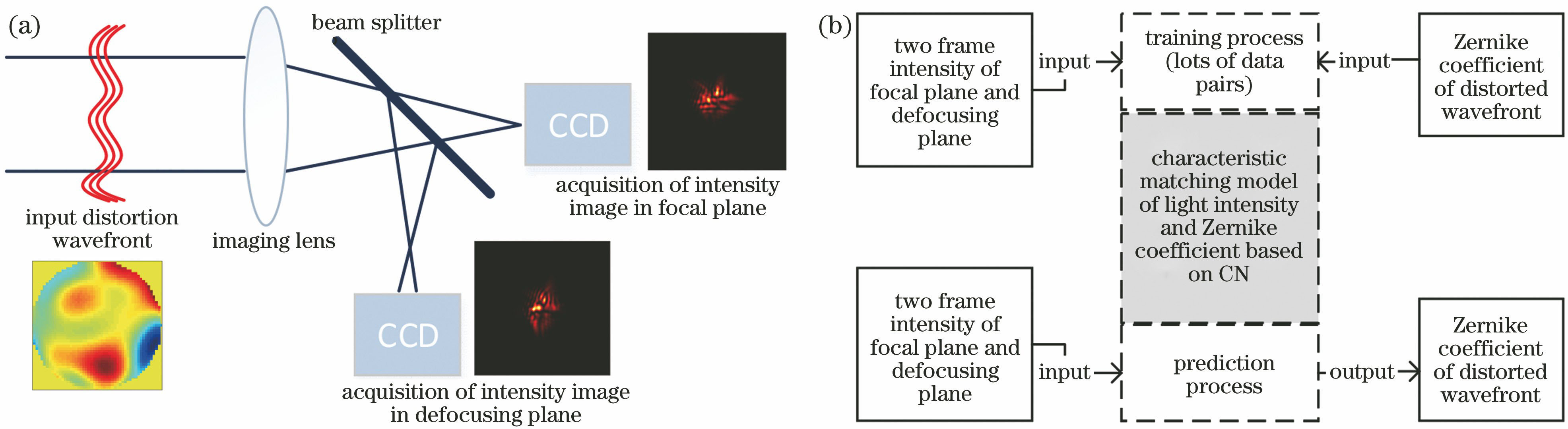
Fig. 1. Basic principle diagram of wavefront restoration based on CNN. (a) Diagram of optical path; (b) training and prediction data structure of CNN
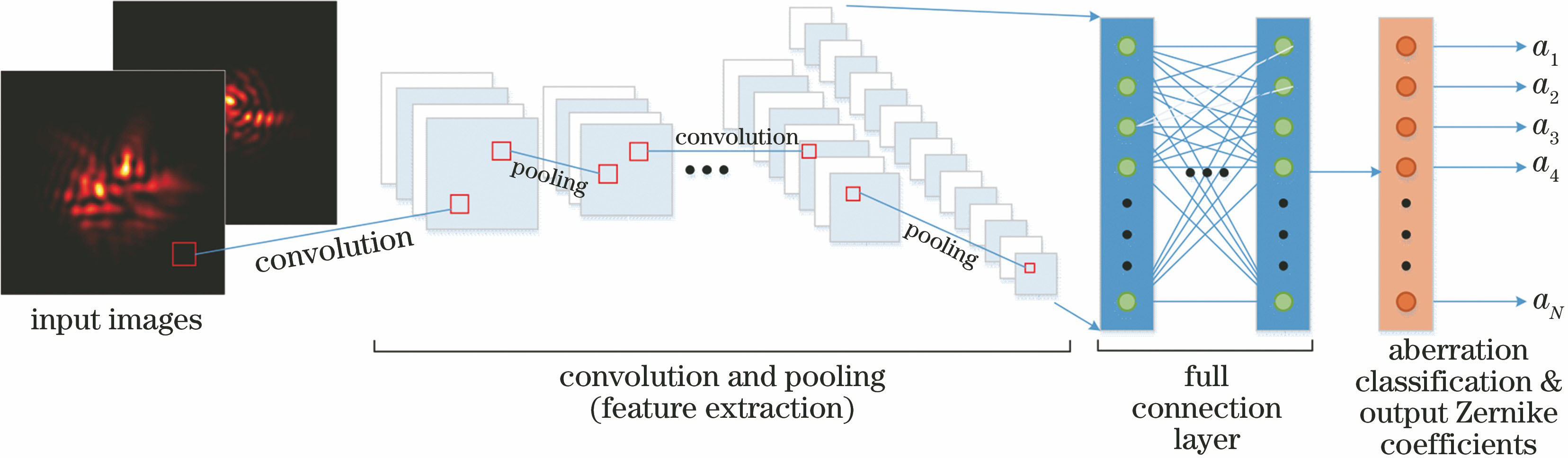
Fig. 2. Diagram of CNN structure used for wavefront restoration
Fig. 3. Eight-layer CNN model for wavefront restoration
Fig. 4. Loss function curves in network training and testing processes. (a) D/r0=5; (b) D/r0=15; (c) D/r0=1-15
Fig. 5. Single-frame aberration randomly generated at D/r0=5 and its restoration results. (a) Wavefront to be restored; intensity images of (b1) focal plane and (b2) defocus plane; (c1) wavefront restored by CNNM1; (c2) residual aberration restored by CNNM1; (d1) wavefront restored by CNNM3; (d2) residual aberration restored by CNNM3
Fig. 6. Single-frame aberration randomly generated at D/r0=15 and its restoration results. (a) Wavefront to be restored; intensity images of (b1) focal plane and (b2) defocus plane; (c1) wavefront restored by CNNM2; (c2) residual aberration restored by CNNM2; (d1) wavefront restored by CNNM3; (d2) residual aberration restored by CNNM3
Fig. 7. Comparison between actual Zernike coefficient and predicted Zernike coefficients by CNNM1,CNNM2, and CNNM3. (a) D/r0=5; (b) D/r0=15
Fig. 8. Strehl ratio of axial light intensity before and after distortion wavefront compensation. (a) D/r0=5; (b) D/r0=15; (c) D/r0=1-15
| ||||||||||||||||||||||||||||||||||||||
Table 1. Description of training and testing data volumes
|
Table 2. Parameters of CNN network model for wavefront restoration

Set citation alerts for the article
Please enter your email address
© Copyright 2018-2021 | Chinese Laser Press. All Rights Reserved 沪ICP备15018463号-20