• Acta Optica Sinica
  • Vol. 41, Issue 20, 2011001 (2021)
Zhichang Mo1、2, Jingsong Wei2、*, and Qing Cao1
Author Affiliations
  • 1College of Sciences, Shanghai University, Shanghai 200444, China
  • 2Laboratory of Micro-Nano Optoelectronic Materials and Devices, Shanghai Institute of Optics and Fine Mechanics, Chinese Academy of Sciences, Shanghai 201800, China
  • show less
    DOI: 10.3788/AOS202141.2011001 Cite this Article Set citation alerts
    Zhichang Mo, Jingsong Wei, Qing Cao. Study on Imaging Characteristics of Multilayer Micropatterns[J]. Acta Optica Sinica, 2021, 41(20): 2011001 Copy Citation Text show less
    Schematic diagram of the micropattern preparation. (a) Process flow diagram; (b) schematic diagram of the laser writing system
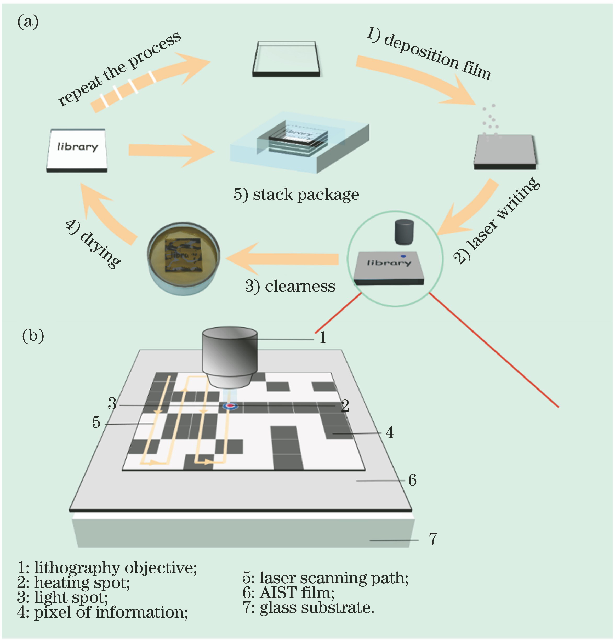
    Fig. 1. Schematic diagram of the micropattern preparation. (a) Process flow diagram; (b) schematic diagram of the laser writing system
    Characteristics of single-layer micropattern. (a) Transmittances of glass substrate and micro pattern; (b) principle of multilayer imaging
    Fig. 2. Characteristics of single-layer micropattern. (a) Transmittances of glass substrate and micro pattern; (b) principle of multilayer imaging
    SEM image of the micropattern
    Fig. 3. SEM image of the micropattern
    Imaging results of the optical microscope. (a) Multilayer micropatterns; (b) resolution plate images under glass substrates with different layers
    Fig. 4. Imaging results of the optical microscope. (a) Multilayer micropatterns; (b) resolution plate images under glass substrates with different layers
    Simulation results of the light field. (a) Influence of crosstalk on the model; (b) field distribution after plane wave incident; (c) field distribution after random light field incident
    Fig. 5. Simulation results of the light field. (a) Influence of crosstalk on the model; (b) field distribution after plane wave incident; (c) field distribution after random light field incident
    MTF of the system under glass of different thicknesses. (a) D=0.34 mm; (b) D=3.4 mm; (c) D=6.8 mm (single layer); (d) D=6.8 mm (multilayer)
    Fig. 6. MTF of the system under glass of different thicknesses. (a) D=0.34 mm; (b) D=3.4 mm; (c) D=6.8 mm (single layer); (d) D=6.8 mm (multilayer)
    Signal diagram under different layers. (a) Interception position of the light intensity signal; (b) signal diagrams at different layers
    Fig. 7. Signal diagram under different layers. (a) Interception position of the light intensity signal; (b) signal diagrams at different layers
    Different paths in the back and forth reflection and the offset distance of the object plane
    Fig. 8. Different paths in the back and forth reflection and the offset distance of the object plane
    Simulation diagram of the reflected field light intensity. (a) Distribution of the reflected field on the object surface; (b) distribution of the light field after passing through all the interfaces
    Fig. 9. Simulation diagram of the reflected field light intensity. (a) Distribution of the reflected field on the object surface; (b) distribution of the light field after passing through all the interfaces
    Bottom layer imaging results of different filling media. (a) Air; (b) ethanol
    Fig. 10. Bottom layer imaging results of different filling media. (a) Air; (b) ethanol
    Contrast of different images. (a) Original image; (b) processed image
    Fig. 11. Contrast of different images. (a) Original image; (b) processed image
    q(q≤2m-1)Initial point: oInitial point: o'
    pΔdpΔd
    0m2ngDm2d
    1m2ngD+2dm-12ngD+2d
    2m-14ngD+2dm-12ngD+4d
    3m-14ngD+4dm-24ngD+4d
    2k,k=0,1,…m-q2q(ngD+d)+2ngDm-q2q(ngD+d)+2d
    2k+1,k=0,1,…m+12-q2(q+1)(ngD+d)m-12-q2(q+1)(ngD+d)
    Table 1. Parameters under different m conditions
    Zhichang Mo, Jingsong Wei, Qing Cao. Study on Imaging Characteristics of Multilayer Micropatterns[J]. Acta Optica Sinica, 2021, 41(20): 2011001
    Download Citation